EP2168488B1 - Système de tomodensitométrie radiographique destiné à l'imagerie de radiographie à contrastes de phases et/ou de radiographie à champ obscur - Google Patents
Système de tomodensitométrie radiographique destiné à l'imagerie de radiographie à contrastes de phases et/ou de radiographie à champ obscur Download PDFInfo
- Publication number
- EP2168488B1 EP2168488B1 EP08017240A EP08017240A EP2168488B1 EP 2168488 B1 EP2168488 B1 EP 2168488B1 EP 08017240 A EP08017240 A EP 08017240A EP 08017240 A EP08017240 A EP 08017240A EP 2168488 B1 EP2168488 B1 EP 2168488B1
- Authority
- EP
- European Patent Office
- Prior art keywords
- grating
- ray
- grating structure
- radiation
- period
- Prior art date
- Legal status (The legal status is an assumption and is not a legal conclusion. Google has not performed a legal analysis and makes no representation as to the accuracy of the status listed.)
- Active
Links
Images


Classifications
-
- G—PHYSICS
- G01—MEASURING; TESTING
- G01N—INVESTIGATING OR ANALYSING MATERIALS BY DETERMINING THEIR CHEMICAL OR PHYSICAL PROPERTIES
- G01N23/00—Investigating or analysing materials by the use of wave or particle radiation, e.g. X-rays or neutrons, not covered by groups G01N3/00 – G01N17/00, G01N21/00 or G01N22/00
- G01N23/02—Investigating or analysing materials by the use of wave or particle radiation, e.g. X-rays or neutrons, not covered by groups G01N3/00 – G01N17/00, G01N21/00 or G01N22/00 by transmitting the radiation through the material
- G01N23/04—Investigating or analysing materials by the use of wave or particle radiation, e.g. X-rays or neutrons, not covered by groups G01N3/00 – G01N17/00, G01N21/00 or G01N22/00 by transmitting the radiation through the material and forming images of the material
- G01N23/046—Investigating or analysing materials by the use of wave or particle radiation, e.g. X-rays or neutrons, not covered by groups G01N3/00 – G01N17/00, G01N21/00 or G01N22/00 by transmitting the radiation through the material and forming images of the material using tomography, e.g. computed tomography [CT]
-
- A—HUMAN NECESSITIES
- A61—MEDICAL OR VETERINARY SCIENCE; HYGIENE
- A61B—DIAGNOSIS; SURGERY; IDENTIFICATION
- A61B6/00—Apparatus or devices for radiation diagnosis; Apparatus or devices for radiation diagnosis combined with radiation therapy equipment
- A61B6/02—Arrangements for diagnosis sequentially in different planes; Stereoscopic radiation diagnosis
- A61B6/03—Computed tomography [CT]
- A61B6/032—Transmission computed tomography [CT]
-
- A—HUMAN NECESSITIES
- A61—MEDICAL OR VETERINARY SCIENCE; HYGIENE
- A61B—DIAGNOSIS; SURGERY; IDENTIFICATION
- A61B6/00—Apparatus or devices for radiation diagnosis; Apparatus or devices for radiation diagnosis combined with radiation therapy equipment
- A61B6/06—Diaphragms
-
- A—HUMAN NECESSITIES
- A61—MEDICAL OR VETERINARY SCIENCE; HYGIENE
- A61B—DIAGNOSIS; SURGERY; IDENTIFICATION
- A61B6/00—Apparatus or devices for radiation diagnosis; Apparatus or devices for radiation diagnosis combined with radiation therapy equipment
- A61B6/42—Arrangements for detecting radiation specially adapted for radiation diagnosis
- A61B6/4291—Arrangements for detecting radiation specially adapted for radiation diagnosis the detector being combined with a grid or grating
-
- A—HUMAN NECESSITIES
- A61—MEDICAL OR VETERINARY SCIENCE; HYGIENE
- A61B—DIAGNOSIS; SURGERY; IDENTIFICATION
- A61B6/00—Apparatus or devices for radiation diagnosis; Apparatus or devices for radiation diagnosis combined with radiation therapy equipment
- A61B6/48—Diagnostic techniques
- A61B6/483—Diagnostic techniques involving scattered radiation
-
- A—HUMAN NECESSITIES
- A61—MEDICAL OR VETERINARY SCIENCE; HYGIENE
- A61B—DIAGNOSIS; SURGERY; IDENTIFICATION
- A61B6/00—Apparatus or devices for radiation diagnosis; Apparatus or devices for radiation diagnosis combined with radiation therapy equipment
- A61B6/48—Diagnostic techniques
- A61B6/484—Diagnostic techniques involving phase contrast X-ray imaging
-
- G—PHYSICS
- G01—MEASURING; TESTING
- G01N—INVESTIGATING OR ANALYSING MATERIALS BY DETERMINING THEIR CHEMICAL OR PHYSICAL PROPERTIES
- G01N2223/00—Investigating materials by wave or particle radiation
- G01N2223/40—Imaging
- G01N2223/419—Imaging computed tomograph
-
- G—PHYSICS
- G01—MEASURING; TESTING
- G01N—INVESTIGATING OR ANALYSING MATERIALS BY DETERMINING THEIR CHEMICAL OR PHYSICAL PROPERTIES
- G01N2223/00—Investigating materials by wave or particle radiation
- G01N2223/60—Specific applications or type of materials
- G01N2223/612—Specific applications or type of materials biological material
-
- G—PHYSICS
- G21—NUCLEAR PHYSICS; NUCLEAR ENGINEERING
- G21K—HANDLING OF PARTICLES OR IONISING RADIATION NOT OTHERWISE PROVIDED FOR; IRRADIATION DEVICES; GAMMA RAY OR X-RAY MICROSCOPES
- G21K2207/00—Particular details of imaging devices or methods using ionizing electromagnetic radiation such as X-rays or gamma rays
- G21K2207/005—Methods and devices obtaining contrast from non-absorbing interaction of the radiation with matter, e.g. phase contrast
Definitions
- Such X-ray CT system for X-ray phase contrast and / or X-ray dark field imaging of a scanned examination object are well known.
- X-ray optical grids allows on the one hand the recording of X-ray images in the phase contrast, which provide additional information about an examination subject and / or allow less radiation dose with the same image contrast.
- phase information which provide additional information about an examination subject and / or allow less radiation dose with the same image contrast.
- amplitude information of scattered radiation is used for imaging.
- an imaging can be generated which is based exclusively on the scatter parts of the X-ray radiation diffracted by the examination object, ie a minimum angle scattering.
- very small density differences in the examination subject can be displayed very high resolution.
- three grating structures must be used, whose periods are approximately in the range of 1 to 100 microns.
- the webs of the central lattice structure - the analysis lattice - consist of phase-shifting material and produce a phase shift of ⁇ or ⁇ / 2 according to T. Weitkamp, et al .: Proc. SPIE 6318, Developments in X-Ray Tomography V (2006) p. 6318-28 ,
- the other two lattice structures usually also consist of lattices, which are formed as absorption lattice with webs of absorbent material with the highest possible absorption.
- the technical realization of the grating structure G 2 with absorber structures turns out to be problematic because it has the smallest grating period p 2 and the grating lines must have a high absorption. This requires the use of highly absorbent materials such as gold. At the same time, the area of G 2 is the largest of all three grids, which in addition to the production cost also requires a significant amount of expensive gold.
- FIG. 5 shows a CT system with a grating interferometer in which the examination object is arranged between the second and third grids, the distance between the first two grids being smaller than the distance between the last two grids.
- no value-based analysis of the spatial intensity profile per detector element is carried out, and thus the phase and amplitude of this intensity profile are not determined analytically.
- the object of the invention is to find an X-ray CT system for X-ray phase contrast and / or X-ray dark field imaging of a scanned examination object with at least one grating interferometer arranged on a gantry, which is used for the Talbot conditions Grid structures sets lower technical requirements and which is suitable for practical operation for the investigation of objects in the size of human patients.
- the inventors have recognized the following:
- the grating G 1 which is illuminated by a spherical wave with the radius 1 and the wavelength ⁇ , generates an interference pattern with maximum contrast by the Talbot effect at a distance TD '.
- the grating period p 2 of the third grating structure G 2 is greater than the grating period p 1 of the second grating structure G 1 and this in turn larger than the grating period p 2 of the second grating structure G 2 . Since, geometrically, the first grating structure G 0 has a smaller surface area than the second grating structure and less than the third grating structure, this results in a considerably simpler structure of the interferometer.
- phase sensitivity of the conventional and the arrangement proposed here is the same according to current findings.
- the improvement according to the invention consists in that the third lattice structure has a lattice period that is larger by a factor of 2 to 5 than the lattice period of the first lattice structure.
- the at least one grating interferometer has a beam path which has a widening of at least 30 °, preferably of at least 35 ° to 40 °, in the direction of a rotation angle of the gantry.
- the examination object can be positioned between the second lattice structure and the third lattice structure, as a result of which a relatively large and central measurement field can result.
- an extension of the first lattice structure in the circumferential direction of the gantry which is 1 to 3 cm, preferably about 2 cm, is selected.
- the extent of the third lattice structure in the direction of the largest fanning out of the radiation used can be at least a factor of two greater than the extent of the second lattice structure in the direction of the greatest fanning out of the radiation used.
- the first grating structure may comprise a source grating with a focus of an X-ray source upstream in the beam direction.
- the first grating structure can also be formed by radiation maxima and radiation minima alternately emerging in strip form on an anode.
- Another way to generate strip-shaped radiation maxima and minima on a surface is to provide a working on electro-magnetic base deflection device of an electron beam which scans the anode surface strip-shaped with the electron beam and thus generates the strip-shaped alternately exiting radiation maxima and radiation minima.
- This variant of the training is in the document EP 1 803 398 A1 shown.
- the third grating structure may be constructed such that it has at least one analysis grating with a spatially resolving detector having a plurality of detector elements arranged thereafter.
- a device for controlled spatial displacement perpendicular to its grating lines and with a spatial resolution in the region of the period of the first grating structure can be provided.
- the second grating structure can also have a device for controlled spatial displacement perpendicular to its grating lines and with a spatial resolution in the region of the period of the first grating structure or else the third grating structure has a device for controlled spatial displacement perpendicular to its grating lines and with a spatial resolution in the region of the period of the third grating structure.
- lattice structures instead of the movement of lattice structures, it is also possible to use a third lattice structure, which is formed by a multiplicity of per detector detected X-ray beam in a strip-like, spatially resolved detector elements, as described for example in the document DE 10 2006 017 290 A1 is described.
- C1 X-ray CT system
- C2 gantry housing
- C3 gantry opening
- C4 sliding patient bed
- C5 patient
- C6 system axis
- C7 control and computing unit
- C8 memory
- d distance between second grid and third grid
- D detector
- E i detector elements
- F focus
- G 0 source grid
- G 1 phase grating
- G 2 analysis grid
- 1 distance between first grid and second grid
- M measuring field
- p 0 grating period of the first grating structure
- p 1 grating period of the second grating structure
- p 2 grating period of the third lattice structure
- Prg 1 prg n computer programs
- r radius
- s distance between first grid and third grid
- S radius
- s distance between first grid and third grid
- S radius
- s distance between first grid and third grid
- S radius
- s distance between first grid and third grid
- S radius
- s distance between first grid and
- FIG. 1 An X-ray CT system C1 for X-ray phase contrast and / or X-ray dark field imaging of a scanned examination object with at least one grating interferometer arranged on a gantry can be seen in 3D representation.
- the system consists essentially of a gantry housing C2, a movable patient bed C4 and a control and processing unit C7.
- a gantry opening C3 can be seen in the gantry housing C2, the diameter of which corresponds approximately to twice the radius 2r of the measuring field of the or the - not visible here - grid interferometer on the gantry.
- the grating structures of the grating interferometers used here are arranged relative to the measuring field and thus to the gantry opening C3 such that the phase grating is located on the source side and the analysis grating structure on the detector side.
- the grating structures are thus also designed with respect to their grating periods such that the relatively smallest grating structure of the source grating G 0 also has the smallest grating period p 0 and the largest grating structure of the grating grating G 2 also has the largest grating period p 2 wherein the phase grating G 1 is arranged with respect to expansion and grating period therebetween.
- the patient C5 is pushed sequentially or continuously through the measurement field with the aid of the displaceable patient bed C4 with the gantry rotating along the system axis C6, wherein a scan is performed by the one or more grid interferometers rotating about the system axis C6 with the gantry.
- the phase differences of adjacent coherent X-rays are quantitatively determined and / or dark field CT images are reconstructed from projections similar to the known dark field recordings from microscopy.
- the diffracted radiation components of the scanning X-ray radiation are first determined from a multiplicity of projection angles.
- the computer programs Prg 1 -Prg n can be used here, which are stored in a memory C8 of the control and arithmetic unit C7 and can be called up and executed as required.
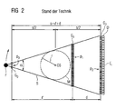
- FIG. 2 shows the basic structure of a grating interferometer in a previously used arrangement with its typical dimensions.
- a focus F is shown a radiation source links, which a with respect to the grating period p 0 relatively coarsely precipitating first absorption grating as follows source grating G 0th
- the measuring field M is arranged, which corresponds approximately to the gantry opening C3 with the radius r.
- the measuring field M is arranged concentrically to the system axis C6 of the gantry.
- the phase grating G 1 follows with a smaller period p 1 and thereupon the third grating structure G 2 with an even smaller grating period p 2 .
- the grating structure G 2 is formed by the analysis grating itself and a subsequent detector D with its detector elements E i .
- this arrangement requires on the detector side a surface area very large and at the same time, however, very finely structured absorption grating as a third lattice structure.
- Such an embodiment is, however, only very expensive to realize ⁇ with a large expansion.
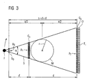
- FIG. 3 Such an exemplary structure of a grating interferometer according to the invention is in the FIG. 3 shown.
- the characteristic distances s, 1 and d are - as well as in the FIG. 2 - also marked.
- a grating interferometer to be used in a CT system can be dimensioned on the one hand, a sufficiently large measuring field with a radius r of 700 mm remains between the second and third lattice structure and, on the other hand, be achieved in the region of the third lattice structure for lattice periods of greater than 10 ⁇ m, which can be produced with a still reasonable outlay.
- FIG. 4 For a better understanding of the measuring principle of the CT systems according to the invention with grating interferometers, is still on the FIG. 4 directed.
- a large-area focus F as an X-ray source and a subsequently arranged source grid G 0 , which here forms the first lattice structure represented.
- quasi-coherent X-rays are emitted in strips at the gaps of the source grating G 0 , while they are largely suppressed in the region of the absorption of the webs of the grating.
- two adjacent coherent X-rays S 1 and S 2 are shown which impinge on a phase grating G 1 in which a diffraction of the beams takes place, so that an interference pattern of the diffracted X-radiation arises following the phase grating G 1 .
- a third grid the analysis grid, which is disposed upstream of a detector D with a plurality of detector elements E i .
- this course of the intensity curve is determined in terms of value as a function of the displacement of a grating and measurement of the radiation intensity as a function of the grating positions. From the knowledge of this course, the phases x 0 can then be evaluated for the phase-contrast imaging, or the average values I med and the deflection amplitude I amp can be evaluated in a known manner for dark-field imaging.
Landscapes
- Health & Medical Sciences (AREA)
- Life Sciences & Earth Sciences (AREA)
- Engineering & Computer Science (AREA)
- Medical Informatics (AREA)
- Pathology (AREA)
- General Health & Medical Sciences (AREA)
- Physics & Mathematics (AREA)
- Nuclear Medicine, Radiotherapy & Molecular Imaging (AREA)
- Radiology & Medical Imaging (AREA)
- Surgery (AREA)
- Veterinary Medicine (AREA)
- Biomedical Technology (AREA)
- Heart & Thoracic Surgery (AREA)
- Molecular Biology (AREA)
- High Energy & Nuclear Physics (AREA)
- Animal Behavior & Ethology (AREA)
- Biophysics (AREA)
- Public Health (AREA)
- Optics & Photonics (AREA)
- Pulmonology (AREA)
- Theoretical Computer Science (AREA)
- Toxicology (AREA)
- Chemical & Material Sciences (AREA)
- Analytical Chemistry (AREA)
- Biochemistry (AREA)
- General Physics & Mathematics (AREA)
- Immunology (AREA)
- Apparatus For Radiation Diagnosis (AREA)
- Analysing Materials By The Use Of Radiation (AREA)
Claims (19)
- Système de tomodensitométrie par rayons X (C1) destiné à l'imagerie à contraste de phase par rayons X et/ou à fond noir par rayons X d'un objet à examiner (C5) balayé, comprenant au moins un interféromètre à réseau disposé sur un portique, ledit au moins un interféromètre à réseau comprenant :1.1. une première structure de réseau (G0), comprenant une pluralité de maxima et de minima d'émission de rayons X disposés en forme de bande et en parallèle et possédant une première période de réseau (p0),1.2. une deuxième structure de réseau (G1) en forme de bande, produisant en tant que réseau de phase un décalage de phase partiel d'un rayonnement X traversant et ayant une deuxième période de réseau (p1),1.3. une troisième structure de réseau (G2) en forme de bande avec une troisième période de réseau (p2), utilisée pour détecter un décalage de phase relatif de rayons X voisins (S1, S2) et/ou leurs taux de dispersion,1.4. dans lequel les trois structures de réseau (G0, G1, G2) remplissent les conditions de Talbot en ce qui concerne les distances (1, d) entre elles et dans lequel au moins la première et la deuxième structures de réseau (G0, G1) remplissent les conditions de Talbot en ce qui concerne leurs périodes de réseau (p0, p1), et1.5. un dispositif pour déterminer en termes de valeur la phase entre rayons X voisins et/ou pour déterminer en termes de valeur l'évolution spatiale de l'intensité par élément détecteur perpendiculairement aux bandes des structures de réseaux,
caractérisé en ce que1.6. la troisième structure de réseau (G2) a une période de réseau (p2) plus grande d'un facteur 2 à 5 que la période de réseau (p0) de la première structure de réseau (G0). - Système de tomodensitométrie par rayons X (C1) selon la revendication précédente 1, caractérisé en ce que ledit au moins un interféromètre à réseau possède une trajectoire du faisceau présentant en direction d'un angle de rotation du portique un évasement (α) d'au moins 30°.
- Système de tomodensitométrie par rayons X (C1) selon l'une des revendications précédentes 1 ou 2, caractérisé en ce que ledit au moins un interféromètre à réseau possède une trajectoire du faisceau présentant en direction d'un angle de rotation du portique un évasement (α) compris entre 35° et 40°.
- Système de tomodensitométrie par rayons X (C1) selon l'une des revendications précédentes 1 à 3, caractérisé en ce que l'objet à examiner est positionné entre la deuxième structure de réseau (G1) et la troisième structure de réseau (G2).
- Système de tomodensitométrie par rayons X (C1) selon l'une des revendications précédentes 1 à 4, caractérisé en ce que l'extension de la première structure de réseau (G0) en direction circonférentielle du portique est de 1 à 3 cm.
- Système de tomodensitométrie par rayons X (C1) selon l'une des revendications précédentes 1 à 5, caractérisé en ce que l'extension de la troisième structure de réseau (G2) en direction de la plus grande étendue du faisceau utilisé est plus grande au moins d'un facteur 2 que l'extension de la deuxième structure de réseau (G1) en direction de la plus grande étendue du faisceau utilisé.
- Système de tomodensitométrie par rayons X (C1) selon l'une des revendications précédentes 1 à 6, caractérisé en ce que le rapport (l/d) entre la distance (1) séparant la première et deuxième structures de réseau (G0, G1) et la distance séparant la deuxième et troisième structures de réseau (G1, G2) est inférieur à 1.
- Système de tomodensitométrie par rayons X (C1) selon l'une des revendications précédentes 1 à 6, caractérisé en ce que le rapport (l/d) entre la distance (1) séparant la première et deuxième structures de réseau (G0, G1) et la distance séparant la deuxième et troisième structures de réseau (G1, G2) est compris entre les valeurs l/d = 0,5 à 0,1.
- Système de tomodensitométrie par rayons X (C1) selon l'une des revendications précédentes 1 à 8, caractérisé en ce que la première structure de réseau (G0) comprend un réseau de source (G0) avec un foyer (F) disposé en amont en direction du faisceau d'une source de rayons X.
- Système de tomodensitométrie par rayons X (C1) selon l'une des revendications précédentes 1 à 8, caractérisé en ce que la première structure de réseau (G0) est formée par des maxima de rayonnement et des minima de rayonnement émergeant à tour de rôle en forme de bande sur une anode.
- Système de tomodensitométrie par rayons X (C1) selon la revendication précédente 10, caractérisé en ce que l'anode est munie d'une surface à structure non homogène, donnant naissance aux maxima de rayonnement et minima de rayonnement émergeant à tour de rôle en forme de bande.
- Système de tomodensitométrie par rayons X (C1) selon la revendication précédente 11, caractérisé en ce que la surface de l'anode est munie de reliefs et/ou de creux disposés en forme de bande.
- Système de tomodensitométrie par rayons X (C1) selon la revendication précédente 11, caractérisé en ce que la surface de l'anode comprend des matériaux disposés en forme de bande et ayant des numéros atomiques distincts.
- Système de tomodensitométrie par rayons X (C1) selon la revendication précédente 10, caractérisé en ce qu'il est prévu un dispositif de déflexion d'un faisceau d'électrons à fonctionnement électromagnétique, qui balaye en forme de bande la surface de l'anode avec le faisceau d'électrons et produit ainsi les maxima de rayonnement et minima de rayonnement émergeant à tour de rôle en forme de bande.
- Système de tomodensitométrie par rayons X (C1) selon l'une des revendications précédentes 1 à 14, caractérisé en ce que la troisième structure de réseau (G2) comprend au moins un réseau d'analyse muni d'un détecteur (D) avec résolution spatiale disposé en aval composé d'une pluralité d'éléments détecteurs (Ei).
- Système de tomodensitométrie par rayons X (C1) selon l'une des revendications précédentes 1 à 15, caractérisé en ce que la première structure de réseau (G0) comprend un dispositif permettant un décalage spatial contrôlé perpendiculairement à ses lignes de réseau et doté d'une résolution spatiale dans le domaine de la période (p0) de la première structure de réseau (G0).
- Système de tomodensitométrie par rayons X (C1) selon l'une des revendications précédentes 1 à 15, caractérisé en ce que la deuxième structure de réseau (G1) comprend un dispositif permettant un décalage spatial contrôlé perpendiculairement à ses lignes de réseau et doté d'une résolution spatiale dans le domaine de la période (p1) de la deuxième structure de réseau (G1).
- Système de tomodensitométrie par rayons X (C1) selon l'une des revendications précédentes 1 à 15, caractérisé en ce que la troisième structure de réseau (G2) comprend un dispositif permettant un décalage spatial contrôlé perpendiculairement à ses lignes de réseau et doté d'une résolution spatiale dans le domaine de la période (p2) de la troisième structure de réseau (G2).
- Système de tomodensitométrie par rayons X (C1) selon l'une des revendications précédentes 1 à 14, caractérisé en ce que la troisième structure de réseau (G2) est formée par une pluralité d'éléments détecteurs (E1) avec résolution spatiale en forme de bande par rayons X détectée.
Priority Applications (3)
| Application Number | Priority Date | Filing Date | Title |
|---|---|---|---|
| EP08017240A EP2168488B1 (fr) | 2008-09-30 | 2008-09-30 | Système de tomodensitométrie radiographique destiné à l'imagerie de radiographie à contrastes de phases et/ou de radiographie à champ obscur |
| DE102009043067A DE102009043067A1 (de) | 2008-09-30 | 2009-09-25 | Röntgen-CT-System zur Röntgen-Phasenkontrast- und/oder Röntgen-Dunkelfeld-Bildgebung |
| US12/570,178 US7983381B2 (en) | 2008-09-30 | 2009-09-30 | X-ray CT system for x-ray phase contrast and/or x-ray dark field imaging |
Applications Claiming Priority (1)
| Application Number | Priority Date | Filing Date | Title |
|---|---|---|---|
| EP08017240A EP2168488B1 (fr) | 2008-09-30 | 2008-09-30 | Système de tomodensitométrie radiographique destiné à l'imagerie de radiographie à contrastes de phases et/ou de radiographie à champ obscur |
Publications (2)
| Publication Number | Publication Date |
|---|---|
| EP2168488A1 EP2168488A1 (fr) | 2010-03-31 |
| EP2168488B1 true EP2168488B1 (fr) | 2013-02-13 |
Family
ID=40445441
Family Applications (1)
| Application Number | Title | Priority Date | Filing Date |
|---|---|---|---|
| EP08017240A Active EP2168488B1 (fr) | 2008-09-30 | 2008-09-30 | Système de tomodensitométrie radiographique destiné à l'imagerie de radiographie à contrastes de phases et/ou de radiographie à champ obscur |
Country Status (3)
| Country | Link |
|---|---|
| US (1) | US7983381B2 (fr) |
| EP (1) | EP2168488B1 (fr) |
| DE (1) | DE102009043067A1 (fr) |
Cited By (2)
| Publication number | Priority date | Publication date | Assignee | Title |
|---|---|---|---|---|
| CN107847199A (zh) * | 2015-06-30 | 2018-03-27 | 皇家飞利浦有限公司 | 具有全视场探测器的扫描x射线装置 |
| CN109580667A (zh) * | 2018-12-05 | 2019-04-05 | 中国科学技术大学 | 单光栅相衬成像方法及系统 |
Families Citing this family (70)
| Publication number | Priority date | Publication date | Assignee | Title |
|---|---|---|---|---|
| JP5339975B2 (ja) * | 2008-03-13 | 2013-11-13 | キヤノン株式会社 | X線位相イメージングに用いられる位相格子、該位相格子を用いたx線位相コントラスト像の撮像装置、x線コンピューター断層撮影システム |
| DE102009004702B4 (de) * | 2009-01-15 | 2019-01-31 | Paul Scherer Institut | Anordnung und Verfahren zur projektiven und/oder tomographischen Phasenkontrastbildgebung mit Röntgenstrahlung |
| KR101180067B1 (ko) | 2010-05-25 | 2012-09-05 | 단국대학교 산학협력단 | 엑스선 직렬 격자 간섭계 |
| RU2572644C2 (ru) * | 2010-10-19 | 2016-01-20 | Конинклейке Филипс Электроникс Н.В. | Формирование дифференциальных фазово-контрастных изображений |
| CN103189739B (zh) * | 2010-10-19 | 2015-12-02 | 皇家飞利浦电子股份有限公司 | 微分相位对比成像 |
| JP2012095865A (ja) * | 2010-11-02 | 2012-05-24 | Fujifilm Corp | 放射線撮影装置、放射線撮影システム |
| US20130223595A1 (en) * | 2010-11-08 | 2013-08-29 | Koninklijke Philips Electronics N.V. | Grating for phase contrast imaging |
| JP5150711B2 (ja) * | 2010-12-07 | 2013-02-27 | 富士フイルム株式会社 | 放射線撮影装置及び放射線撮影システム |
| CN103648388B (zh) * | 2011-07-04 | 2017-05-03 | 皇家飞利浦有限公司 | 相位对比度成像设备 |
| US9486175B2 (en) | 2011-07-04 | 2016-11-08 | Koninklijke Philips N.V. | Phase contrast imaging apparatus |
| AU2012290646B2 (en) * | 2011-07-29 | 2014-09-04 | The Johns Hopkins University | Differential phase contrast X-ray imaging system and components |
| DE102011082878A1 (de) * | 2011-09-16 | 2013-03-21 | Siemens Aktiengesellschaft | Röntgendetektor einer gitterbasierten Phasenkontrast-Röntgenvorrichtung und Verfahren zum Betreiben einer gitterbasierten Phasenkontrast-Röntgenvorrichtung |
| US20130108015A1 (en) * | 2011-10-28 | 2013-05-02 | Csem Centre Suisse D'electronique Et De Microtechnique S.A - Recherche Et Developpement | X-ray interferometer |
| US20150117599A1 (en) * | 2013-10-31 | 2015-04-30 | Sigray, Inc. | X-ray interferometric imaging system |
| RU2624513C2 (ru) * | 2012-01-24 | 2017-07-04 | Конинклейке Филипс Н.В. | Мультинаправленная фазоконтрастная рентгеновская визуализация |
| EP2822468B1 (fr) * | 2012-03-05 | 2017-11-01 | University Of Rochester | Procédés et appareils pour tdm à faisceau conique à contraste de phase différentiel et tdm à faisceau conique hybride |
| DE102012005767A1 (de) * | 2012-03-25 | 2013-09-26 | DüRR DENTAL AG | Phasenkontrast-Röntgen-Tomographiegerät |
| KR101378757B1 (ko) * | 2012-08-30 | 2014-03-27 | 한국원자력연구원 | 물질 원소 정보 획득 및 영상 차원의 선택이 가능한 방사선 영상화 장치 |
| US8989347B2 (en) | 2012-12-19 | 2015-03-24 | General Electric Company | Image reconstruction method for differential phase contrast X-ray imaging |
| US9014333B2 (en) | 2012-12-31 | 2015-04-21 | General Electric Company | Image reconstruction methods for differential phase contrast X-ray imaging |
| JP2014178130A (ja) * | 2013-03-13 | 2014-09-25 | Canon Inc | X線撮像装置及びx線撮像システム |
| DE102013205406A1 (de) * | 2013-03-27 | 2014-10-16 | Siemens Aktiengesellschaft | Röntgenaufnahmesystem zur Röntgenbildgebung bei hohen Bildfrequenzen eines Untersuchungsobjekts mittels direkter Messung des Interferenzmusters |
| JP2015072263A (ja) * | 2013-09-09 | 2015-04-16 | キヤノン株式会社 | X線撮像システム |
| US10297359B2 (en) | 2013-09-19 | 2019-05-21 | Sigray, Inc. | X-ray illumination system with multiple target microstructures |
| US10269528B2 (en) | 2013-09-19 | 2019-04-23 | Sigray, Inc. | Diverging X-ray sources using linear accumulation |
| US10295485B2 (en) | 2013-12-05 | 2019-05-21 | Sigray, Inc. | X-ray transmission spectrometer system |
| USRE48612E1 (en) | 2013-10-31 | 2021-06-29 | Sigray, Inc. | X-ray interferometric imaging system |
| US10304580B2 (en) | 2013-10-31 | 2019-05-28 | Sigray, Inc. | Talbot X-ray microscope |
| US20160270198A1 (en) * | 2013-11-05 | 2016-09-15 | Koninklijke Philips N.V. | X-ray imaging device with fast spatial modulation of photon flux |
| CN104622492A (zh) * | 2013-11-11 | 2015-05-20 | 中国科学技术大学 | 一种x射线光栅相位衬度成像装置和方法 |
| JP2015166676A (ja) * | 2014-03-03 | 2015-09-24 | キヤノン株式会社 | X線撮像システム |
| EP2942619A1 (fr) | 2014-05-07 | 2015-11-11 | Paul Scherrer Institut | Approche pour ouverture inclinée d'interférométrie à réseau de diffraction de rayons X |
| US10401309B2 (en) | 2014-05-15 | 2019-09-03 | Sigray, Inc. | X-ray techniques using structured illumination |
| US10117629B2 (en) | 2014-12-03 | 2018-11-06 | Board Of Supervisors Of Louisiana State University And Agricultural And Mechanical College | High energy grating techniques |
| US10352880B2 (en) | 2015-04-29 | 2019-07-16 | Sigray, Inc. | Method and apparatus for x-ray microscopy |
| CN107580473A (zh) * | 2015-05-06 | 2018-01-12 | 皇家飞利浦有限公司 | X射线成像 |
| US10295486B2 (en) | 2015-08-18 | 2019-05-21 | Sigray, Inc. | Detector for X-rays with high spatial and high spectral resolution |
| US11116465B2 (en) | 2015-09-16 | 2021-09-14 | Koninklijke Philips N.V. | Dark-field enhanced virtual x-ray colonoscopy |
| CN107024490B (zh) * | 2016-01-29 | 2019-07-05 | 中国科学院高能物理研究所 | 一次曝光光栅剪切成像装置及数据采集与信息提取方法 |
| CN109690627A (zh) | 2016-09-08 | 2019-04-26 | 皇家飞利浦有限公司 | 改进的相衬和暗场ct重建算法 |
| WO2018087195A1 (fr) * | 2016-11-10 | 2018-05-17 | Koninklijke Philips N.V. | Imagerie par contraste de phase basée sur réseau |
| US10247683B2 (en) | 2016-12-03 | 2019-04-02 | Sigray, Inc. | Material measurement techniques using multiple X-ray micro-beams |
| US11026643B2 (en) | 2016-12-06 | 2021-06-08 | Koninklijke Philips N.V. | Interferometer grating support for grating-based x-ray imaging and/or a support bracket therefor |
| WO2018175570A1 (fr) | 2017-03-22 | 2018-09-27 | Sigray, Inc. | Procédé de réalisation d'une spectroscopie des rayons x et système de spectromètre d'absorption de rayons x |
| EP3435325A1 (fr) | 2017-07-26 | 2019-01-30 | Koninklijke Philips N.V. | Correction de la diffusion pour l'imagerie en champ sombre |
| EP3454051A1 (fr) | 2017-09-06 | 2019-03-13 | Koninklijke Philips N.V. | Réseau de diffraction pour contraste de phase aux rayons x et/ou imagerie sur fond noir |
| EP3494885A1 (fr) * | 2017-12-07 | 2019-06-12 | Koninklijke Philips N.V. | Appareil de présentation d'informations d'image à rayons x de champ sombre |
| US10578566B2 (en) | 2018-04-03 | 2020-03-03 | Sigray, Inc. | X-ray emission spectrometer system |
| US10845491B2 (en) | 2018-06-04 | 2020-11-24 | Sigray, Inc. | Energy-resolving x-ray detection system |
| GB2591630B (en) | 2018-07-26 | 2023-05-24 | Sigray Inc | High brightness x-ray reflection source |
| US10656105B2 (en) | 2018-08-06 | 2020-05-19 | Sigray, Inc. | Talbot-lau x-ray source and interferometric system |
| US10962491B2 (en) | 2018-09-04 | 2021-03-30 | Sigray, Inc. | System and method for x-ray fluorescence with filtering |
| DE112019004478T5 (de) | 2018-09-07 | 2021-07-08 | Sigray, Inc. | System und verfahren zur röntgenanalyse mit wählbarer tiefe |
| US11143605B2 (en) | 2019-09-03 | 2021-10-12 | Sigray, Inc. | System and method for computed laminography x-ray fluorescence imaging |
| US11175243B1 (en) | 2020-02-06 | 2021-11-16 | Sigray, Inc. | X-ray dark-field in-line inspection for semiconductor samples |
| CN115667896B (zh) | 2020-05-18 | 2024-06-21 | 斯格瑞公司 | 使用晶体分析器和多个检测元件的x射线吸收光谱的系统和方法 |
| EP3933881A1 (fr) | 2020-06-30 | 2022-01-05 | VEC Imaging GmbH & Co. KG | Source de rayons x à plusieurs réseaux |
| JP7640682B2 (ja) | 2020-09-17 | 2025-03-05 | シグレイ、インコーポレイテッド | X線を用いた深さ分解計測および分析のためのシステムおよび方法 |
| US12480892B2 (en) | 2020-12-07 | 2025-11-25 | Sigray, Inc. | High throughput 3D x-ray imaging system using a transmission x-ray source |
| KR102927910B1 (ko) | 2020-12-07 | 2026-02-19 | 시그레이, 아이엔씨. | 투과 x-선 소스를 이용한 고처리량 3D x-선 이미징 시스템 |
| US12360067B2 (en) | 2022-03-02 | 2025-07-15 | Sigray, Inc. | X-ray fluorescence system and x-ray source with electrically insulative target material |
| DE112023001408T5 (de) | 2022-03-15 | 2025-02-13 | Sigray, Inc. | System und verfahren für die kompakte laminographie unter verwendung einer mikrofokus-transmissionsröntgenquelle und eines röntgendetektors mit variabler vergrösserung |
| DE112023002079T5 (de) | 2022-05-02 | 2025-02-27 | Sigray, Inc. | Sequenzielles wellenlängendispersives röntgenspektrometer |
| US12230468B2 (en) | 2022-06-30 | 2025-02-18 | Varex Imaging Corporation | X-ray system with field emitters and arc protection |
| WO2024173256A1 (fr) | 2023-02-16 | 2024-08-22 | Sigray, Inc. | Système détecteur de rayons x avec au moins deux diffracteurs de bragg plats empilés |
| US12181423B1 (en) | 2023-09-07 | 2024-12-31 | Sigray, Inc. | Secondary image removal using high resolution x-ray transmission sources |
| WO2025101530A1 (fr) | 2023-11-07 | 2025-05-15 | Sigray, Inc. | Système et procédé de spectroscopie d'absorption des rayons x utilisant des informations spectrales provenant de deux plans orthogonaux |
| WO2025151383A1 (fr) | 2024-01-08 | 2025-07-17 | Sigray, Inc. | Système d'analyse par rayons x à faisceau de rayons x focalisé et à microscope non à rayons x |
| WO2025155719A1 (fr) | 2024-01-18 | 2025-07-24 | Sigray, Inc. | Réseau séquentiel de détecteurs d'imagerie par rayons x |
| WO2025174966A1 (fr) | 2024-02-15 | 2025-08-21 | Sigray, Inc. | Système et procédé de génération d'un faisceau de rayons x focalisé |
Family Cites Families (11)
| Publication number | Priority date | Publication date | Assignee | Title |
|---|---|---|---|---|
| US5812629A (en) | 1997-04-30 | 1998-09-22 | Clauser; John F. | Ultrahigh resolution interferometric x-ray imaging |
| JP4445397B2 (ja) | 2002-12-26 | 2010-04-07 | 敦 百生 | X線撮像装置および撮像方法 |
| EP1731099A1 (fr) * | 2005-06-06 | 2006-12-13 | Paul Scherrer Institut | Interféromètre pour l'imagerie et la tomographie à contraste de phase avec une source de rayons X incohérente et polychromatique |
| DE102005035464A1 (de) | 2005-07-28 | 2007-02-01 | BSH Bosch und Siemens Hausgeräte GmbH | Hausgerätebedienvorrichtung |
| DE502006007410D1 (de) | 2005-12-27 | 2010-08-26 | Paul Scherrer Inst Psi | Fokus-Detektor-Anordnung zur Erzeugung von Phasenkontrast-Röntgenaufnahmen und Verfahren hierzu |
| DE102005062447A1 (de) | 2005-12-27 | 2007-07-05 | Siemens Ag | Vorrichtung zur Erzeugung eines Röntgenbilds |
| DE102006035677A1 (de) * | 2006-02-01 | 2007-08-16 | Siemens Ag | Verfahren und CT-System zur Erkennung und Differenzierung von Plaque in Gefäßstrukturen eines Patienten |
| DE102006017290B4 (de) | 2006-02-01 | 2017-06-22 | Siemens Healthcare Gmbh | Fokus/Detektor-System einer Röntgenapparatur, Röntgen-System und Verfahren zur Erzeugung von Phasenkontrastaufnahmen |
| DE102006037282B4 (de) * | 2006-02-01 | 2017-08-17 | Siemens Healthcare Gmbh | Fokus-Detektor-Anordnung mit röntgenoptischem Gitter zur Phasenkontrastmessung |
| WO2007125833A1 (fr) * | 2006-04-24 | 2007-11-08 | The University Of Tokyo | Dispositif de recuperation d'images radiologiques et procede de recuperation d'images radiologiques |
| DE102008048688B4 (de) * | 2008-09-24 | 2011-08-25 | Paul Scherrer Institut | Röntgen-CT-System zur Erzeugung tomographischer Phasenkontrast- oder Dunkelfeldaufnahmen |
-
2008
- 2008-09-30 EP EP08017240A patent/EP2168488B1/fr active Active
-
2009
- 2009-09-25 DE DE102009043067A patent/DE102009043067A1/de not_active Withdrawn
- 2009-09-30 US US12/570,178 patent/US7983381B2/en active Active
Non-Patent Citations (1)
| Title |
|---|
| MOMOSE A ET AL: "Biomedical imaging by Talbot-type X-ray phase tomography", PROCEEDINGS OF THE SPIE - THE INTERNATIONAL SOCIETY FOR OPTICAL ENGINEERING SPIE - THE INTERNATIONAL SOCIETY FOR OPTICAL ENGINEERING USA, vol. 6318, 7 September 2006 (2006-09-07), pages 63180T - 1, ISSN: 0277-786X * |
Cited By (3)
| Publication number | Priority date | Publication date | Assignee | Title |
|---|---|---|---|---|
| CN107847199A (zh) * | 2015-06-30 | 2018-03-27 | 皇家飞利浦有限公司 | 具有全视场探测器的扫描x射线装置 |
| CN107847199B (zh) * | 2015-06-30 | 2021-08-17 | 皇家飞利浦有限公司 | 具有全视场探测器的扫描x射线装置 |
| CN109580667A (zh) * | 2018-12-05 | 2019-04-05 | 中国科学技术大学 | 单光栅相衬成像方法及系统 |
Also Published As
| Publication number | Publication date |
|---|---|
| US7983381B2 (en) | 2011-07-19 |
| DE102009043067A1 (de) | 2010-04-22 |
| US20100091936A1 (en) | 2010-04-15 |
| EP2168488A1 (fr) | 2010-03-31 |
Similar Documents
| Publication | Publication Date | Title |
|---|---|---|
| EP2168488B1 (fr) | Système de tomodensitométrie radiographique destiné à l'imagerie de radiographie à contrastes de phases et/ou de radiographie à champ obscur | |
| DE102006015356B4 (de) | Verfahren zur Erzeugung projektiver und tomographischer Phasenkontrastaufnahmen mit einem Röntgen-System | |
| DE102008048688B4 (de) | Röntgen-CT-System zur Erzeugung tomographischer Phasenkontrast- oder Dunkelfeldaufnahmen | |
| DE102006037254B4 (de) | Fokus-Detektor-Anordnung zur Erzeugung projektiver oder tomographischer Phasenkontrastaufnahmen mit röntgenoptischen Gittern, sowie Röntgen-System, Röntgen-C-Bogen-System und Röntgen-Computer-Tomographie-System | |
| DE102006017291B4 (de) | Fokus/Detektor-System einer Röntgenapparatur zur Erzeugung von Phasenkontrastaufnahmen, Röntgensystem mit einem solchen Fokus/Detektor-System sowie zugehöriges Speichermedium und Verfahren | |
| DE102006017290B4 (de) | Fokus/Detektor-System einer Röntgenapparatur, Röntgen-System und Verfahren zur Erzeugung von Phasenkontrastaufnahmen | |
| DE102006063048B3 (de) | Fokus/Detektor-System einer Röntgenapparatur zur Erzeugung von Phasenkontrastaufnahmen | |
| DE102009004702B4 (de) | Anordnung und Verfahren zur projektiven und/oder tomographischen Phasenkontrastbildgebung mit Röntgenstrahlung | |
| DE102006015358B4 (de) | Fokus/Detektor-System einer Röntgenapparatur zur Erzeugung von Phasenkontrastaufnahmen, zugehöriges Röntgen-System sowie Speichermedium und Verfahren zur Erzeugung tomographischer Aufnahmen | |
| EP1803398B1 (fr) | Agencement d'une source et d'un détecteur pour l'imagerie à rayons X à contraste de phase et procédé associé | |
| DE102006037255A1 (de) | Fokus-Detektor-Anordnung einer Röntgenapparatur zur Erzeugung projektiver oder tomographischer Phasenkontrastaufnahmen | |
| DE102006037281A1 (de) | Röntgenoptisches Durchstrahlungsgitter einer Fokus-Detektor-Anordnung einer Röntgenapparatur zur Erzeugung projektiver oder tomographischer Phasenkontrastaufnahmen von einem Untersuchungsobjekt | |
| DE102006037256B4 (de) | Fokus-Detektor-Anordnung einer Röntgenapparatur zur Erzeugung projektiver oder tomographischer Phasenkontrastaufnahmen sowie Röntgensystem, Röntgen-C-Bogen-System und Röntgen-CT-System | |
| DE69310295T2 (de) | Verbesserter röntgenstrahlenraumcomputertomographscanner | |
| DE102006037257B4 (de) | Verfahren und Messanordnung zur zerstörungsfreien Analyse eines Untersuchungsobjektes mit Röntgenstrahlung | |
| DE102006037282B4 (de) | Fokus-Detektor-Anordnung mit röntgenoptischem Gitter zur Phasenkontrastmessung | |
| DE60222768T2 (de) | Computertomograph | |
| DE102006035677A1 (de) | Verfahren und CT-System zur Erkennung und Differenzierung von Plaque in Gefäßstrukturen eines Patienten | |
| EP0028431B1 (fr) | Dispositif pour la mesure de la répartition de densité d'un rayonnement dispersé dans une zône plane à examiner | |
| DE10009285A1 (de) | Computertomograph zur Ermittlung des Impulsübertrags-Spektrums in einem Untersuchungsbereich | |
| DE102011082878A1 (de) | Röntgendetektor einer gitterbasierten Phasenkontrast-Röntgenvorrichtung und Verfahren zum Betreiben einer gitterbasierten Phasenkontrast-Röntgenvorrichtung | |
| DE102023211963B4 (de) | Verfahren zur Dualenergiebildgebung eines Aufnahmebereichs mit einer Röntgeneinrichtung und Röntgeneinrichtung | |
| DE3426934C2 (de) | Einrichtung zur Erzeugung tomographischer Bilder eines Körpers | |
| DE102013222386A1 (de) | Verfahren und CT-System zur Topogramm-Abtastung | |
| WO2007074029A1 (fr) | Systeme de detection du foyer pour la creation d'enregistrements a contraste de phases obtenus par rayons x et procede correspondant |
Legal Events
| Date | Code | Title | Description |
|---|---|---|---|
| PUAI | Public reference made under article 153(3) epc to a published international application that has entered the european phase |
Free format text: ORIGINAL CODE: 0009012 |
|
| 17P | Request for examination filed |
Effective date: 20091120 |
|
| AK | Designated contracting states |
Kind code of ref document: A1 Designated state(s): AT BE BG CH CY CZ DE DK EE ES FI FR GB GR HR HU IE IS IT LI LT LU LV MC MT NL NO PL PT RO SE SI SK TR |
|
| AX | Request for extension of the european patent |
Extension state: AL BA MK RS |
|
| AKX | Designation fees paid |
Designated state(s): AT BE BG CH CY CZ DE DK EE ES FI FR GB GR HR HU IE IS IT LI LT LU LV MC MT NL NO PL PT RO SE SI SK TR |
|
| 17Q | First examination report despatched |
Effective date: 20110505 |
|
| GRAP | Despatch of communication of intention to grant a patent |
Free format text: ORIGINAL CODE: EPIDOSNIGR1 |
|
| GRAS | Grant fee paid |
Free format text: ORIGINAL CODE: EPIDOSNIGR3 |
|
| GRAA | (expected) grant |
Free format text: ORIGINAL CODE: 0009210 |
|
| RAP1 | Party data changed (applicant data changed or rights of an application transferred) |
Owner name: SIEMENS AKTIENGESELLSCHAFT Owner name: PAUL SCHERRER INSTITUT |
|
| RBV | Designated contracting states (corrected) |
Designated state(s): DE |
|
| AK | Designated contracting states |
Kind code of ref document: B1 Designated state(s): DE |
|
| RAP2 | Party data changed (patent owner data changed or rights of a patent transferred) |
Owner name: SIEMENS AKTIENGESELLSCHAFT Owner name: PAUL SCHERRER INSTITUT |
|
| REG | Reference to a national code |
Ref country code: DE Ref legal event code: R096 Ref document number: 502008009214 Country of ref document: DE Effective date: 20130404 |
|
| PLBE | No opposition filed within time limit |
Free format text: ORIGINAL CODE: 0009261 |
|
| STAA | Information on the status of an ep patent application or granted ep patent |
Free format text: STATUS: NO OPPOSITION FILED WITHIN TIME LIMIT |
|
| 26N | No opposition filed |
Effective date: 20131114 |
|
| REG | Reference to a national code |
Ref country code: DE Ref legal event code: R097 Ref document number: 502008009214 Country of ref document: DE Effective date: 20131114 |
|
| REG | Reference to a national code |
Ref country code: DE Ref legal event code: R081 Ref document number: 502008009214 Country of ref document: DE Owner name: SIEMENS HEALTHCARE GMBH, DE Free format text: FORMER OWNERS: PAUL SCHERRER INSTITUT, VILLIGEN, CH; SIEMENS AKTIENGESELLSCHAFT, 80333 MUENCHEN, DE Ref country code: DE Ref legal event code: R081 Ref document number: 502008009214 Country of ref document: DE Owner name: PAUL SCHERER INSTITUT, CH Free format text: FORMER OWNERS: PAUL SCHERRER INSTITUT, VILLIGEN, CH; SIEMENS AKTIENGESELLSCHAFT, 80333 MUENCHEN, DE |
|
| REG | Reference to a national code |
Ref country code: DE Ref legal event code: R081 Ref document number: 502008009214 Country of ref document: DE Owner name: SIEMENS HEALTHINEERS AG, DE Free format text: FORMER OWNERS: PAUL SCHERER INSTITUT, VILLIGEN, CH; SIEMENS HEALTHCARE GMBH, MUENCHEN, DE Ref country code: DE Ref legal event code: R081 Ref document number: 502008009214 Country of ref document: DE Owner name: PAUL SCHERER INSTITUT, CH Free format text: FORMER OWNERS: PAUL SCHERER INSTITUT, VILLIGEN, CH; SIEMENS HEALTHCARE GMBH, MUENCHEN, DE |
|
| REG | Reference to a national code |
Ref country code: DE Ref legal event code: R081 Ref document number: 502008009214 Country of ref document: DE Owner name: SIEMENS HEALTHINEERS AG, DE Free format text: FORMER OWNERS: PAUL SCHERER INSTITUT, VILLIGEN, CH; SIEMENS HEALTHINEERS AG, MUENCHEN, DE |
|
| PGFP | Annual fee paid to national office [announced via postgrant information from national office to epo] |
Ref country code: DE Payment date: 20251120 Year of fee payment: 18 |