EP2168647A1 - Récipient de collecte d'échantillons, appareil de collecte d'échantillons, et procédé de collecte d'échantillons dans un système de fluide supercritique - Google Patents
Récipient de collecte d'échantillons, appareil de collecte d'échantillons, et procédé de collecte d'échantillons dans un système de fluide supercritique Download PDFInfo
- Publication number
- EP2168647A1 EP2168647A1 EP20090171172 EP09171172A EP2168647A1 EP 2168647 A1 EP2168647 A1 EP 2168647A1 EP 20090171172 EP20090171172 EP 20090171172 EP 09171172 A EP09171172 A EP 09171172A EP 2168647 A1 EP2168647 A1 EP 2168647A1
- Authority
- EP
- European Patent Office
- Prior art keywords
- vial
- collection
- sample
- sample collection
- aerosol
- Prior art date
- Legal status (The legal status is an assumption and is not a legal conclusion. Google has not performed a legal analysis and makes no representation as to the accuracy of the status listed.)
- Granted
Links
Images


Classifications
-
- B—PERFORMING OPERATIONS; TRANSPORTING
- B01—PHYSICAL OR CHEMICAL PROCESSES OR APPARATUS IN GENERAL
- B01D—SEPARATION
- B01D11/00—Solvent extraction
- B01D11/02—Solvent extraction of solids
- B01D11/0203—Solvent extraction of solids with a supercritical fluid
-
- B—PERFORMING OPERATIONS; TRANSPORTING
- B01—PHYSICAL OR CHEMICAL PROCESSES OR APPARATUS IN GENERAL
- B01D—SEPARATION
- B01D15/00—Separating processes involving the treatment of liquids with solid sorbents; Apparatus therefor
- B01D15/08—Selective adsorption, e.g. chromatography
- B01D15/10—Selective adsorption, e.g. chromatography characterised by constructional or operational features
- B01D15/24—Selective adsorption, e.g. chromatography characterised by constructional or operational features relating to the treatment of the fractions to be distributed
- B01D15/247—Fraction collectors
-
- B—PERFORMING OPERATIONS; TRANSPORTING
- B01—PHYSICAL OR CHEMICAL PROCESSES OR APPARATUS IN GENERAL
- B01D—SEPARATION
- B01D45/00—Separating dispersed particles from gases or vapours by gravity, inertia, or centrifugal forces
- B01D45/12—Separating dispersed particles from gases or vapours by gravity, inertia, or centrifugal forces by centrifugal forces
- B01D45/16—Separating dispersed particles from gases or vapours by gravity, inertia, or centrifugal forces by centrifugal forces generated by the winding course of the gas stream, the centrifugal forces being generated solely or partly by mechanical means, e.g. fixed swirl vanes
-
- G—PHYSICS
- G01—MEASURING; TESTING
- G01N—INVESTIGATING OR ANALYSING MATERIALS BY DETERMINING THEIR CHEMICAL OR PHYSICAL PROPERTIES
- G01N1/00—Sampling; Preparing specimens for investigation
- G01N1/02—Devices for withdrawing samples
- G01N1/22—Devices for withdrawing samples in the gaseous state
- G01N1/2202—Devices for withdrawing samples in the gaseous state involving separation of sample components during sampling
- G01N1/2211—Devices for withdrawing samples in the gaseous state involving separation of sample components during sampling with cyclones
-
- B—PERFORMING OPERATIONS; TRANSPORTING
- B01—PHYSICAL OR CHEMICAL PROCESSES OR APPARATUS IN GENERAL
- B01D—SEPARATION
- B01D15/00—Separating processes involving the treatment of liquids with solid sorbents; Apparatus therefor
- B01D15/08—Selective adsorption, e.g. chromatography
- B01D15/26—Selective adsorption, e.g. chromatography characterised by the separation mechanism
- B01D15/40—Selective adsorption, e.g. chromatography characterised by the separation mechanism using supercritical fluid as mobile phase or eluent
-
- G—PHYSICS
- G01—MEASURING; TESTING
- G01N—INVESTIGATING OR ANALYSING MATERIALS BY DETERMINING THEIR CHEMICAL OR PHYSICAL PROPERTIES
- G01N1/00—Sampling; Preparing specimens for investigation
- G01N1/02—Devices for withdrawing samples
- G01N1/22—Devices for withdrawing samples in the gaseous state
- G01N1/2202—Devices for withdrawing samples in the gaseous state involving separation of sample components during sampling
- G01N2001/222—Other features
- G01N2001/2223—Other features aerosol sampling devices
-
- G—PHYSICS
- G01—MEASURING; TESTING
- G01N—INVESTIGATING OR ANALYSING MATERIALS BY DETERMINING THEIR CHEMICAL OR PHYSICAL PROPERTIES
- G01N30/00—Investigating or analysing materials by separation into components using adsorption, absorption or similar phenomena or using ion-exchange, e.g. chromatography or field flow fractionation
- G01N30/02—Column chromatography
- G01N30/04—Preparation or injection of sample to be analysed
- G01N30/24—Automatic injection systems
Definitions
- the present invention relates to an improved sample collection container, a sample collection apparatus including the sample collection container, and a sample collection method using the sample collection container in a supercritical fluid system.
- Japanese Patent Laid-Open No. 2002-71534 discloses a sample collection method used in any of the supercritical fluid systems described above which involves discharging a supercritical fluid containing a sample separated and eluted in a column (a mixed fluid of liquid-phase CO 2 and organic solvents) through an automatic back pressure regulator, transferring the supercritical fluid through a multi-port distribution value to a large number of corresponding transfer tubes, and loaded the supercritical fluid from the transfer tubes into bottles in a collection chamber maintained at a predetermined pressure (20 to 100 psi ⁇ 0.14 to 0.69 MPa).
- the transfer tubes are heated and the collection chamber and the bottles are maintained under the pressure described above.
- flow path is cooled by endoergic reaction owing to adiabatic expansion of CO 2 , and thus the sample tends to be a solid.
- the Gas-liquid-phase fluid is spirally delivered into the bottles.
- the gas-phase CO 2 is discharged from the bottles under a predetermined pressure, and the liquid-phase organic solvents are collected in the bottles.
- Japanese Patent Laid-Open No. 2007-120972 discloses a sample collection apparatus in a supercritical fluid system for collecting a multi-constituent sample injected into a mixed fluid of liquid-phase CO 2 and a modifier.
- the apparatus involves separating the sample in a column for each of the constituents, reducing the pressure of the supercritical fluid containing each of the eluted samples in an automatic back pressure regulator to a pressure close to the atmospheric pressure, fractionating the gas containing the thereby formed aerosol through a flow path distribution valve, delivering each of the fractionated gases through the corresponding line to the corresponding Gas-liquid separator to separate the gas-phase CO 2 and spirally spray the liquid component containing the sample in the Gas-liquid separator to form droplets, and causing the droplets to fall into a collection bottle connected to the Gas-liquid separator. That is, the gas-phase CO 2 and the liquid component are separated from each other in the slightly pressurized Gas-liquid separator.
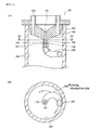
- the Gas-liquid separator 410 includes a Gas-liquid separating unit 421 most of which is inserted into the collection container 400, an exhausting gas unit 441 provided on the Gas-liquid separating unit 421, and a clipping unit 451 used to attach the Gas-liquid separator 410 to the collection container 400.
- the Gas-liquid separating unit 421 is as a whole placed on the upper end of the collection container 400 and fixed thereto by a seat 422.
- An introduction line 423 for introducing a gas containing a fractionated aerosol is provided on a side of an upper end portion of the Gas-liquid separating unit 421 so that the gas flows into a cylindrical space S 1 , which will be described later, in a tangential direction.
- a heater 424 having the cylindrical space S 1 is provided downstream of the introduction line 423.
- a sintered stainless filter 432 having a cylindrical shape with a bottom is fixed to the lower end of the heater 424 by a fixing buffer plate 431 and hanged therefrom.
- the structure described above forms a separating unit 433.
- a space S 2 surrounded by the sintered filter 432 connects with the space S 1 in the heater 424.
- a discharge duct 443 is connected to the upper end of the space S 1 in the heater 424, and a discharge duct 444 is connected to the discharge duct 443.
- An upper clipping part 453 of the clipping unit 451 is attached to an upper end portion of the Gas-liquid separating unit 421, and the Gas-liquid separator 410 is attached and detached to and from the collection container 400 via an openable lower clipping part 454 that grips the neck of the collection container 400.
- the lower clipping part 454 is opened and closed by operating a movable lever 452 of the clipping unit 451.
- the adhesion between the liquid component and the sintered stainless filter 432 is greater than the force that causes the liquid component passing through the micro pore in the sintered stainless filter 432 to scatter, whereby the scattering of the liquid component will be suppressed.
- the liquid component moves downward due to the gravity and drops through the bottom of the sintered stainless filter 432 into the collection container 400.
- the sample collection method used in a supercritical fluid system described in Japanese Patent Laid-Open No. 2002-71534 is disadvantageous in cost of the increased apparatus because the bottles for collecting the sample are kept being pressurized. Further, since a multi-port distribution valve is used, the number of ports disadvantageously limits the number of sample constituents that can be separated.
- the supercritical fluid system illustrated in Japanese Patent Laid-Open No. 2007-120972 also not only uses a multi-port flow path distribution value but also requires Gas-liquid separators. That is, both in Japanese Patent Laid-Open Nos. 2002-71534 and 2007-120972 , when the number of sample constituents increases, the multi-port distribution valve needs to have ports corresponding to the number of sample constituents. The larger the number of ports, the more expensive the multi-port distribution valve is. When no multi-port distribution valve with the necessary number of ports is commercially available, multiple multi-port distribution valves are used, resulting in complicated control.
- a supercritical chromatography apparatus that includes a sample collection apparatus with Gas-liquid separators and uses a mixed fluid of liquid-phase CO 2 and a modifier as a supercritical fluid will be described as an example of related art before the present invention is described.
- Figure 1 is a schematic view showing a typical configuration of such an apparatus.
- liquid-phase CO 2 supplied from a CO 2 cylinder 11 into a line is delivered to a heat exchanger in a CO 2 pump 13 and cooled down to -10°C by the heat exchanger to completely turn to liquid-phase CO 2 .
- the thus sufficiently cooled liquid-phase CO 2 is pumped through a pumping head of the CO 2 pump 13 at a high pressure.
- a modifier pump 14 delivers a modifier supplied from a modifier container 12 into the pumped liquid-phase CO 2 , and the modifier is mixed with the liquid-phase CO 2 .
- the mixed fluid which is a supercritical fluid, is heated by a pre-heating coil 15 to a temperature suitable for separation in a column 19, which will be described later, and then delivered to a loop-injection-type injector 16.
- a syringe pump 17 delivers a sample to the loop, the sample is injected to the column 19 by switching the injector 16.
- the sample having been injected into the mixed fluid and dissolved therein is loaded in the column 19 in a column oven 18 and separated into each constituent of the sample.
- Each of the sample constituents contained in the mixed fluid eluted from the column 19 is monitored by a detector 20 responding to any of the characteristics of the sample (optical absorbance, for example), and then reaches an automatic back pressure regulator 21.
- the pressure of the mixed fluid from the CO 2 pump 13 and the modifier pump 14 to the automatic back pressure regulator 21 is adjusted to a predetermined value by the automatic back pressure regulator 21.
- the pressure of the mixed fluid ranges from approximately 10 to 35 MPa on the side upstream of the automatic back pressure regulator 21, and becomes approximately normal pressure on the side downstream of the automatic back pressure regulator 21. Therefore, the liquid-phase CO 2 undergoes adiabatic expansion and evaporates, and the temperature thereof decreases. At this point, the sample is dissolved in the liquid component primarily formed of the modifier. The rapidly expanding gas-phase CO 2 aerosolizes the liquid component, which is then transferred through the line.
- a second object of the present invention is to provide a sample collection apparatus including the sample collection container and a sample collection method using the sample collection container.
- a sample collection container according to claim 1 used in a supercritical fluid system comprises a cylindrical collection vial into which an aerosol-containing gas formed by reducing the pressure of a supercritical fluid containing a sample eluted in a separating unit to a pressure close to the atmospheric pressure is loaded to collect the sample, and a vial cap attached to an upper end opening of the collection vial.
- the vial cap includes a discharge hole through which the collection vial connects with the outer air and an introduction path through which the aerosol-containing gas is externally introduced into the collection vial.
- a distal end portion of the introduction path has an opening in the vicinity of the inner circumferential surface of the collection vial, and the opening is oriented in the tangential direction of the inner circumferential surface or in a direction downwardly-inclined from the tangential direction.
- the aerosol-containing gas is injected under the atmospheric pressure.
- the trapped liquid component then grows into droplets, the diameter of which increases due to successive aerosol collision, and the droplets move downward and are collected at the bottom of the collection vial.
- the sample collection container according claim 3 is the sample collection container according claim 2, wherein the introduction tube includes a straight portion connected to the introduction hole and a spiral portion following the straight portion and extending along the inner circumferential surface of the collection vial.
- the sample can be collected by causing the liquid component sprayed out of the tip of the spiral portion of the introduction tube to fall and swirl along the inner circumferential surface of the collection vial.
- the sample collection container according claim 4 is the sample collection container according claim 2 or 3, wherein the distal end portion of the introduction tube attached to the vial cap is cut in a slanting direction.
- a gas is smoothly separated from the aerosol-containing gas sprayed out of the opening of the distal end portion of the introduction tube.
- the sample collection container according claim 5 is the sample collection container according claim 1, wherein the introduction path is formed of an introduction hole vertically drilled in the vial cap, a introduction hole drilled in a cylindrical extension extending from the vial cap into the collection vial, and a plurality of distribution holes extending from the introduction hole to the outer circumferential surface of the extension, each of the distribution holes having an opening at the outer circumferential surface.
- the introduction path since the introduction path itself does not vibrate and the aerosol-containing gas to be injected is distributed into the plurality of distribution holes, the speed at which the aerosol-containing gas is sprayed out through the opening of each of distribution holes is greatly reduced, whereby the sample can be collected in a stable manner.
- the sample collection container according claim 6 is the sample collection container according claim 5, wherein each of the distribution holes has an arcuate shape, and horizontally extends from the lower end of the introduction hole or is inclined downward along a conical surface whose apex coincides with the lower end of the introduction hole.
- the sample collection container described above can cause the aerosol-containing gas sprayed out of the opening of each of the distribution holes to fall and swirl along the inner circumferential surface of the collection vial.
- the collection vial serves as a cyclone separator, which increases the sample collection efficiency.
- the sample collection container according claim 7 is the sample collection container according claim 1, wherein at least an upper portion of the vial cap is shaped into a truncated cone, and the outer circumferential surface of the upper portion is supported by the end of an upper end opening of the collection vial or a flange provided at the periphery of the vial cap is placed on the end of the upper end opening of the collection vial.
- the vial cap supported by or placed on the upper end portion of the collection vial will not slide sideward, and the vial cap is very easily attached and detached to and from the collection vial.
- a sample collection apparatus is used in a supercritical fluid system in which a gas containing a liquid component in the form of aerosol formed by reducing the pressure of a supercritical fluid containing a sample eluted in a separating unit to a pressure close to the atmospheric pressure is fractionated and the gas containing the fractionated aerosol is dispensed into a sample collection containers
- the sample collection apparatus comprises a plurality of sample collection containers, each of which includes the cylindrical collection vial and the vial cap according to any of claims 1 to 7, and a probe that can be moved to a position above each of the collection vials, the probe lowered from the position above the collection vial and dispensing the gas containing the fractionated aerosol into the collection vial under the atmospheric pressure.
- gas-phase CO 2 that undergoes adiabatic expansion causes the liquid component containing the sample to disperse and transfer the liquid component to a mist-like aerosol.
- the aerosol-containing gas is fractionated for each of the contained constituents.
- the gas containing the fractionated aerosol travels from a distal end portion of the probe to the introduction path in the vial cap.
- the gas containing the fractionated aerosol is then dispensed by spraying it along the inner circumferential surface of the cylindrical collection vial under atmospheric pressure.
- the collection vial is operated to serve as a cyclone separator, whereby the gas component is discharged through the discharge hole provided in the vial cap into the outer air. Therefore, the liquid component containing the sample can be efficiently collected in the collection vial.
- the sample collection method comprises bringing a distal end portion of the probe lowered from above into fluid-leakage-free contact (i.e. intimate contact) with the introduction path in the vial cap, dispensing the gas containing the fractionated aerosol through an end opening of the introduction path into the collection vial, and collecting the liquid component containing the sample in the collection vial and discharging the gas out of the discharge hole in the vial cap into the outer air.
- fluid-leakage-free contact i.e. intimate contact
- gas-phase CO 2 that undergoes adiabatic expansion causes the liquid component containing the sample to disperse and transfer the liquid component to a mist-like aerosol.
- the aerosol-containing gas is fractionated for each of the contained constituents.
- the gas containing the fractionated aerosol travels from a distal end portion of the probe to the introduction path in the vial cap.
- the gas containing the fractionated aerosol is then dispensed by spraying it along the inner circumferential surface of the cylindrical collection vial under atmospheric pressure.
- the collection vial is operated to serve as a cyclone separator, whereby the gas component is discharged through the discharge hole provided in the vial cap into the outer air. Therefore, the liquid component containing the sample can be efficiently collected in the collection vial.
- the sample collection container does not need to be pressure resistant but the vial cap and the collection vial can be made of resin, because the sample collection is performed under the atmospheric pressure. Therefore, typical thermal forming using a mold can be employed, and the vial cap and the collection vial can be manufactured at low cost.
- the collection vial can of course be made of glass.
- the cylindrical collection vial is operated to serve as a cyclone separator, the separated gas, that did not contain the aerosol, rises in the collection vial and is removed out of the discharge hole in the vial cap, whereas the liquid component containing the sample in the form of aerosol collides with the inner circumferential surface of the collection vial and is trapped thereon, grows into droplets, the diameter of which increases due to successive aerosol collision, and moves to the bottom of the collection vial.
- the sample can therefore be collected in the collection vial at high collection efficiency.
- a multi-port distribution valve having a limited number of ports is not used, but a probe that can be moved to a position above each of a large number of collection vials is used to dispense an aerosol-containing gas into a vial cap of the collection vial. Therefore, even when the number of samples to be separated and fractionated is large, all the samples can be collected by preparing collection vials corresponding to the number of samples.
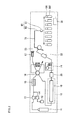
- Figure 2 shows the configuration of a supercritical fluid chromatographic apparatus 2 including a sample collection container of the present invention.
- Figure 2 corresponds to Figure 1 showing the supercritical fluid chromatographic apparatus 1 of related art.
- the components of the apparatus 2 shown in Figure 2 the components that are the same as those of the apparatus 1 shown in Figure 1 have the same reference characters and the description thereof will be omitted.
- the supercritical fluid chromatographic apparatus 2 shown in Figure 2 differs from the apparatus 1 shown in Figure 1 in that the downstream side of the flow path switching valve 23 is connected to a flexible resin tube 39 followed by a stainless steel tube 63 of a probe 60 movable in three directions, X, Y, and Z, and an aerosol-containing gas is dispensed through a probe distal end portion 61 into a large number of collection vials 300, each of which is provided with a vial cap 100. That is, in the supercritical fluid chromatographic apparatus 2, no Gas-liquid separator 27 shown in Figure 1 is provided upstream of each of the vial caps 100 and the collection vials 300.
- the entire apparatus 2 shown in Figure 2 is controlled by a personal computer 38, as in the apparatus 1 shown in Figure 1 .
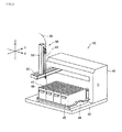
- multiple vial racks 45 are arranged on a tray 44 fixed to a bottom plate 43 to which the XYZ movement mechanism 41 is fixed.
- the cylindrical collection vials 300 combined with the vial caps 100 shown, for example, in Figure 7 , which will be described later, are inserted into and held in a large number of holding holes 47 formed in a top plate 46 of each of the vial racks 45. While the above description has been made with reference to the "Liquid Handler,” any other mechanism having a function similar to that of the "Liquid Handler" may be used.
- Figures 4A and 4B show the vial racks 45.
- Figure 4A is a plan view of four vial racks 45 and shows an example of how the holding holes 47 are arranged in the top plates 46.
- the numerals labeled in the holding holes 47 in the leftmost vial rack 45 represent an example of the order in which the aerosol-containing gas is dispensed.
- Figure 4B is a perspective view of any one of the vial racks 45.
- the XYZ movement mechanism 41 moves the probe 60 relative to the collection vials 300 held in the holding holes 47.
- the probe 60 is formed of the stainless steel tube 63 to which the distal end portion 61 is attached and other components.
- a gas that contains a liquid component aerosol containing a sample is dispensed through the probe distal end portion 61.
- FIG. 5 is an enlarged perspective view showing part of the probe 60 and the XYZ movement mechanism 41.
- a guide groove 54 extending in the up/down direction is provided in a side surface of the vertical arm 53, and a slider 55 including an actuator (not shown) can be moved in the up/down direction (Z direction) along the guide groove 54.
- the stainless steel tube 63 which transfers the aerosol-containing gas, is attached to the slider 55.
- the downstream end of the flexible tube (resin tube, for example) 39 shown in Figure 2 is connected to the upper end of the stainless steel tube 63 via a joint.
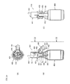
- Figure 6 is a partial cross-sectional view showing the entire probe 60.
- An upper end portion of the stainless steel tube 63 is held on slider 55 in such a way that the stainless steel tube 63 is slidable in the the Z (up/down) direction.
- the lower half of the stainless steel tube 63 is surrounded by a guide pipe 64 for preventing the stainless steel tube 63 from being bent, and a bush 66 that slidably holds the stainless steel tube 63, which moves in the Z direction, is provided at each of the upper and lower ends of the guide pipe 64.
- the guide pipe 64 is fixed to the vertical arm 53 with a fixing member 67.
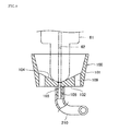
- Figure 7 shows an example of the sample collection container of the present invention.
- the sample collection container shown in Figure 7 is formed of any of the collection vial 300 combined with the vial cap 100 for dispensing the aerosol-containing gas into the collection vial 300 described above.
- the collection vial 300 is formed of a cylindrical body 301 and a wide-mouth neck 302.
- the outer circumferential surface of the vial cap 100, the diameter of which increases toward the upper end, is secured by the wide-mouth neck 302. The attachment and detachment of the vial cap 100 is therefore very readily carried out.
- Figure 8 is an enlarged cross-sectional view showing the vial cap 100.
- a body 101 of the vial cap 100 has a cup-like shape, and the introduction hole 103 extending in the up/down direction is drilled in a central portion of a bottom portion 102 of the body 101.
- An attachment tube 105 protruding from the lower surface of the bottom portion 102 has a hollow hole the axis of which coincides with the axis of the introduction hole 103.
- An introduction tube 210 that introduces the aerosol-containing gas into the collection vial 300 is fitted in and fixed to the outer circumferential surface of the attachment tube 105.
- the introduction tube 210 has an arcuate shape that comes into contact with an inner circumferential surface 308 of the collection vial 300, and is shorter in length than or equal to the circumferential length of the inner circumferential surface 308. Or, the introduction tube 210 does not always have to come into contact with the inner circumferential surface 308 as long as a distal end opening 211 of the introduction tube 210 is located near the inner circumferential surface 308.
- the tip of the introduction tube 210 is inclined downward from the horizontal tangential direction (inclined by an angle ranging from 5 to 20 degrees).
- discharge holes 109 extending from the lower surface of the bottom portion 102 to the inner wall 104 are formed in the vial cap body 101, as shown in Figures 7 and 8 .
- the discharge holes 109 are used to remove the gas-phase CO 2 rising through the collection vial 300 out of the system.
- the detector 20 does not detect any sample in the mixed fluid of the liquid-phase CO 2 and the modifiers delivered from the column 19, the mixed fluid passes through the automatic back pressure regulator 21, where the pressure of the mixed fluid is reduced to a pressure close to the atmospheric pressure. Therefore, the gas-phase CO 2 that undergoes adiabatic expansion aerosolizes the liquid component, which travels through the pre-heater 22 and is discharged out of the system through the flow path switching valve 23, as in the related art.
- the XYZ movement mechanism 41 moves the probe 60 in the X and Y directions to the position immediately above the collection vial 300 held in the holding hole 47 labeled with numeral 1 in one of the vial racks 45 shown in Figure 4A .
- the stainless steel tube 63 is then lowered in the Z direction, and the probe distal end portion 61 comes into intimate contact with the inner wall 104 around the introduction hole 103 provided in the vial cap 100.
- the injection hole 62 in the probe distal end portion 61 is now connected to the introduction hole 103 in the vial cap 100.
- the aerosol-containing gas is therefore transferred downward through the stainless steel tube 63 of the probe 60 via the resin tube 39.
- the gas is then transferred through the vial cap 100, which is in intimate contact with the probe distal end portion 61 located at the lower end of the stainless steel tube 63, into the introduction tube 210 attached to the bottom of the vial cap 100 and housed in the collection vial 300, as shown in Figure 7 .
- the gas is then sprayed in the circumferential but slightly downward direction along the inner circumferential surface 308 of the collection vial 300 through the distal end opening 211 of the introduction tube 210.
- the gas containing the sprayed aerosol gradually falls while swirling along the inner circumferential surface 308 of the collection vial 300.
- the cylindrical collection vial 300 serves as a cyclone separator. That is, the liquid component in the form of aerosol dispersed in the gas-phase CO 2 collides with the inner circumferential surface 308 and is trapped thereon, and the gas-phase CO 2 is separated, rises in the collection vial 300, and exits through the discharge holes 109 in the vial cap 100 into the outer air.
- the liquid component trapped on the inner circumferential surface 308 grows into droplets, the diameter of which increases due to the successive collision of the liquid component, and the droplets flow downward and accumulate at the bottom of the collection vial 300. In this way, the liquid component containing the separated sample is collected at high collection efficiency.
- the flow path switching valve 23 When the detector 20 detects that the first separated sample is completely eluted from the column 19, the flow path switching valve 23 is switched to the position so that the flow path is to be the outside of the system, and the XYZ movement mechanism 41 lifts the stainless steel tube 63 from the collection vial 300 in the Z direction. The stainless steel tube 63 is then moved, for example, in the Y direction and stopped in the next position immediately above the adjacent collection vial 300. The stainless steel tube 63 is then lowered and the probe distal end portion 61 thereby comes into air-tight contact with the vial cap 100 on the adjacent collection vial 300.
- the flow path switching valve 23 is again switched to the position so that the flow path is connected to the probe 60, and the aerosol-containing gas formed in the components downstream of the automatic back pressure regulator 21 is delivered through the resin tube 39 into the stainless steel tube 63 of the probe 60 and dispensed into the adjacent collection vial 300.
- the same operation is repeated multiple times in correspondence with the number of contained samples by using a new collection vial 300 for each operation.
- sample collection container of the present invention can be used in supercritical extraction.
- a supercritical fluid extraction apparatus can be provided by removing the injector 16 and replacing the column 19 with an extraction vessel (a vessel that encloses an extracted substance) in the supercritical fluid chromatographic apparatus 2 shown in Figure 2 .
- the sample collection container of the present invention may be used in a case where the sample collection efficiency is insufficient in high-performance liquid chromatography.
- the XYZ movement mechanism 41 which is the "Liquid Handler” that moves the probe 60 shown in Figure 3 , was used to attempt to collect a sample (warfarin) in the supercritical chromatographic apparatus 2 shown in Figure 2 . That is, a test of whether the sample is collected in any of the collection vials 300 was carried out by lowering the probe distal end portion 61 shown in Figure 7 , which is connected to the stainless steel tube 63, and bringing the probe distal end portion 61 into intimate contact with the inner wall 104 of the vial cap 100.
- the following mixed fluid was used as the mobile phase of supercritical fluid chromatography, and the change in sample collection efficiency versus the flow rate of the supercritical fluid was determined under the following conditions:
- Table 1 shows the sample collection efficiency versus the flow rate of the supercritical fluid under the conditions described above. Since the test was carried out to check the collection efficiency by using pure warfarin, the number of fractionated components is one, and only one collection vial 300 was used.
- Table 1 Sample collection efficiency versus flow rate of supercritical fluid in Invention Example Flow rate of CO 2 g/min Flow rate of ethyl alcohol mL/min Sample collection efficiency % 5 0.5 98 or more 10 1.0 98 or more 30 3.0 98 or more 50 5.0 95 or more
- the "Liquid Handler” was used to carry out a test of whether a sample is collected by forcing a stainless steel tube attached to the tip of the probe 60 to penetrate through a septum interposed between a commercially available collection vial and a screw cap with an opening.
- the septum was precut in advance to discharge gas-phase CO 2 .
- Table 2 shows the sample collection efficiency versus the flow rate of the supercritical fluid in this case.
- the collection efficiency is 98% or greater in Invention Example when the flow rate of the supercritical fluid is increased to 30 g of CO 2 per minute and 3.0 mL of ethyl alcohol per minute, clearly showing a significant improvement in sample collection efficiency in the sample collection method using the apparatus of the present invention.
- Comparative Example greatly differs from Invention Example in that an aerosol-containing gas is sprayed downward into the commercially available, typical collection vial through the tip of the stainless steel tube. Therefore, the aerosol having reached the bottom of the collection vial is reversed, and the gas-phase CO 2 rises toward the discharge cutout and exits therethrough. In this case, the liquid component in which the sample is dissolved accumulates at the bottom of the collection vial, whereas part of the liquid component is discharged along with the CO 2 through the discharge cutout as the flow of the aerosol is reversed. The sample collection efficiency therefore decreases.
- the collection vial 300 serves as a cyclone separator, the gas-phase CO 2 is removed through the discharge holes 109 in the vial cap 100 into the outer air, whereas the liquid component in which the sample is dissolved collides with the inner circumferential surface 308 of the collection vial 300, is trapped thereon, and grows into droplets with increased diameters, which move to the bottom, and accumulate there. The liquid component in which the sample is dissolved is therefore collected at high collection efficiency.
- the introduction tube 210 shown Figure 7 has a straight portion extending downward from the center of the bottom surface of the vial cap 100 and a subsequent portion extending sideward along the inner circumferential surface 308 of the collection vial 300 and having a length shorter than or equal to the circumferential length of the inner circumferential surface 308.
- the introduction tube may alternatively be a spiral introduction tube 220 that swirls along the inner circumferential surface 308 of the collection vial 300 once or twice and is slightly inclined downward (preferably inclined downward by 5 to 20 degrees from the horizontal tangential direction), as shown in Figure 9 .
- the tip of the spiral introduction tube 220 is stably in contact with the inner circumferential surface 308 of the collection vial 300.
- the liquid component having accumulated at the bottom of the collection vial 300 accompanies the gas-phase CO 2 and rises along the inner circumferential surface 308.
- the spiral introduction tube 220 in intimate contact with the inner circumferential surface 308 of the collection vial 300 serves to block the rising liquid modifier and cause the liquid component to return downward. In this way, the liquid modifier will not scatter through the discharge holes 109 in the vial cap 100 along with the gas-phase CO 2 , whereby the sample collection efficiency will not decrease.
- the introduction tube 220 swirls once or twice along the inner circumferential surface 308 of the collection vial 300.
- an O-ring 311 having an outer diameter that is the same as the diameter of the inner circumferential surface 308 may be attached to an upper end portion of the inner circumferential surface 308 of a collection vial 310, as shown in Figure 10 .
- the O-ring enables to suppress the liquid component rising along the inner circumferential surface 308 of the collection vial 310.
- a probe distal end portion 71 with a conical tip may alternatively be attached to the lower end of the stainless steel tube 63, as shown in Figure 11 , and the probe distal end portion 71, when lowered, may come into intimate contact with a conical inner wall 114 of a vial cap 110.
- An injection hole 72 is formed along the axis of the probe distal end portion 71.
- Figure 12 shows a collection vial 320 and a vial cap 120. That is, the collection vial 320 has a cylindrical shape, and a flange 126 provided at the periphery of a body 121 of the vial cap 120 is placed on the edge of an upper end opening 321 of the collection vial 320.
- An upper end portion of the introduction tube 210 is fitted in and fixed to the outer circumferential surface of an attachment tube 125 protruding from a central portion of a bottom portion 122, as in the case shown in Figures 7 and 8 .
- Discharge holes 129 are formed as through holes extending from the bottom surface of the vial cap 120 to the top surface of the vial cap 120.
- the resultant collection unit is more readily assembled and disassembled, and the workability is improved particularly when a large number of collection vials are set.
- FIG. 13A shows the vial cap 120 combined with the collection vial 320 shown in Figure 12 and a grooved attachment tube 135 protruding from the central portion of the bottom portion 122 of the vial cap 120.
- a circumferential guide groove 136 is provided by cutting the outer circumferential surface of the grooved attachment tube 135.
- a perforated circular plate 231 has a hole 232 and is attached to the upper end of the rotating introduction tube 230. And, the plate 231 is fitted in the guide groove 136 via the hole 232.
- Figure 13B is a cross-sectional view taken along the line [B]-[B] shown in Figure 13A .
- a reaction force rotates the rotating introduction tube 230 around the attachment tube 135 in the q direction.
- the aerosol can be uniformly sprayed in all directions toward an inner circumferential surface 328 of the collection vial 320, and the speed at which the aerosol is sprayed toward the inner circumferential surface 328 can be reduced.
- Figures 14A and 14B show a collection vial 330 having a short, wide-mouth neck 332 and a vial cap 140. That is, Figure 14A is a plan view showing the vial cap 140 placed on the collection vial 330, and Figure 14B is a cross-sectional view taken along the line [B]-[B] shown in Figure 14A . As shown in Figure 14B , the vial cap 140 is placed on the end of the opening of the short, wide-mouth neck 332.
- the vial cap 140 includes a funnel-shaped body 141 with discharge holes 149 at the periphery, a flange 146 around the outer circumference of the body 141, a cylindrical skirt 147 extending downward from the bottom surface of the flange 146, and an introduction tube 240.
- the components described above are integrally formed into the vial cap 140.
- the discharge holes 149 are formed at three locations at equal angular spacings in a boundary portion between the body 141 and the outer circumferential flange 146.
- the skirt 147 is not in contact with the inner circumferential surface of the wide-mouth neck 332 of the collection vial 330.
- the skirt 147 serves as a barrier that prevents the liquid modifier rising along an inner circumferential surface 338 of the collection vial 330 from entering the discharge holes 149, the liquid component does not exit through the discharge holes 149 to the outside and no collection loss occurs. Further, since the discharge holes 149 are provided at the periphery of the funnel-shaped body 141 and the upper end opening of each of the discharge holes 149 is lower than the upper end of the funnel-shaped body 141, any liquid modifier attached to the periphery of the upper end opening of each of the discharge holes 149 does not flow into the funnel-shaped body 141 and thus does not contaminate the sample dispensed into the body 141.
- Figure 15 is a cross-sectional view showing the collection vial 300, which is the same as those shown in Figures 7 , 9 , and 10 , that is, the collection vial 300 formed of the body 301 and the wide-mouth neck 302, and a vial cap 150 placed on and fixed to the edge of the opening of the wide-mouth neck 302.
- the vial cap 150 includes a funnel-shaped body 151 with discharge holes 159 formed on the upper end side, an introduction tube 250 with a long straight portion 251 extending downward from and formed integrally with a central bottom portion of the body 151, a cylindrical skirt 157 extending from the bottom surface of the periphery of the body 151 and surrounding the straight portion 251 of the introduction tube 250, and a flange 156 formed at the periphery of the upper end of the skirt 157.
- the components described above are integrally formed into the vial cap 150.
- the flange 156 of the vial cap 150 is placed on the edge of the opening of the wide-mouth neck 302 of the collection vial 300.
- the vial cap 150 is fixed to the collection vial 300 with a perforated screw cap 305. That is, the top portion of the perforated screw cap 305 has a hole 306 into which the body 151 of the vial cap 150 is inserted, and the inner circumferential edge of the hole 306 presses and secures the upper surface of the flange 156 of the vial cap 150.
- a female thread 307 provided on the inner wall of the perforated screw cap 305 engages a male thread 303 formed on the outer circumferential surface of the wide-mouth neck 302. The vial cap 150 is thus fixed to the collection vial 300.
- skirt 157 of the thus configured vial cap 150 again serves as a barrier that prevents the liquid component rising along an inner circumferential surface 308 of the collection vial 300 from entering the discharge holes 159, the liquid modifier does not exit through the discharge holes 159 to the outside and no collection loss occurs.
- Figure 16 is a cross-sectional view showing the cylindrical collection vial 320 and a vial cap 160 placed on the edge of the opening of the collection vial 320.
- the vial cap 160 includes a body 161 having a conical inner wall 164 and discharge holes 169, a flange 166 provided at the periphery of the body 161, an attachment tube 165 protruding downward from a central portion of a bottom portion of the body 161, the introduction tube 210, an upper end portion of which fits on the outer circumferential surface of the attachment tube 165, and a cylindrical member 162 extending downward from the lower surface of the flange 166 and inserted into the collection vial 320 in such a way that the cylindrical member 162 comes into contact with the inner circumferential surface 328 of the collection vial 320.
- a spiral groove 167 slightly inclined downward (preferably inclined downward by 5 to 10 degrees from the horizontal direction) is formed in an inner circumferential surface 168 of the cylindrical member 162.
- An aerosol-containing gas dispensed into the body 161 of the vial cap 160 exits out of the distal end opening 211 of the introduction tube 210 and spirally swirls downward while being guided along the spiral groove 167 in the cylindrical member 162.
- the liquid component collides with the inner circumferential surface 168 of the cylindrical member 162 and is trapped thereon, which grows into droplets, the diameter of which increases due to the successive collision of the liquid component.
- the thus formed droplets fall, whereas the gas-phase CO 2 rises and exits through the discharge holes 169.
- the spiral groove 167 formed in the cylindrical member 162 helps the aerosol-containing gas to swirl, which facilitates trapping the liquid component and contributes to improvement in the sample collection efficiency.
- a vial cap 170 shown in Figures 17A and 17B differs from the vial caps shown in Figures 8 and 11 in that an aerosol-containing gas is not sprayed through an introduction tube, but sprayed through arcuate distribution holes 177 provided in the vial cap 170.
- Figure 17A is a longitudinal cross-sectional view of the vial cap 170. As shown in Figure 17A , the vial cap 170 includes a body 171, an intermediate member 172, and a distribution hole forming member 173. The components described above are integrally formed into the vial cap 170.
- Figure 17B is a cross-sectional view of the vial cap 170 taken along the line [B]-[B] shown in Figure 17A , that is, a plan view of the member 173.
- the intermediate member 172 is a cylindrical member with a introduction hole 175 drilled therein, the introduction hole 175 connecting with an introduction hole 174 in the body 171.
- the member 173 has a central portion 176 and two arcuate symmetrical distribution holes 177 (showed as grooved in Fig. 17B ) formed in the upper surface that is in intimate contact with the bottom surface of the intermediate member 172.
- the central portion 176 corresponds to the lower end of the introduction hole 175, and the two arcuate symmetrical distribution holes 177 extending from the central portion 176 to the outer circumferential surface of member 173 are formed symmetrically with respect to the central portion 176. Therefore, the intermediate member 172 overlaid on the member 173 forms the distribution holes 177.
- the aerosol-containing gas injected into the introduction hole 174 in the body 171 travels through the introduction hole 175 in the intermediate member 172, is distributed through the central portion 176 into the two distribution holes 177 in the member 173, and is sprayed in the tangential direction out of the openings of the distribution holes 177 in the outer circumferential surface of the member 173 to the inner circumferential surface of the collection vial (not shown).
- the distribution holes 177 thus formed in the vial cap 170 do not vibrate or deform, unlike an introduction tube, due to variation in the spray speed, for example, at the time when aerosol introduction starts, whereby the aerosol is sprayed in a stable manner.
- the speed at which the aerosol is sprayed out of the opening of each of the distribution holes 177 is reduced to approximately half the speed when an introduction tube is used, whereby the amount of loss due to scattering is reduced.
- the vial cap 170 also has two discharge holes 179 provided through the member 173, the intermediate member 172, and the body 171 to remove the gas-phase CO 2 rising in the collection vial (not shown). Additionally, two discharge tubes 178 protrude downward from the bottom surface of the member 173, as shown in Figure 17A . The discharge tubes 178 is connects with the discharge holes 179. Therefore, the gas-phase CO 2 rising from below travels through hollow holes in the discharge tubes 178 and then the discharge holes 179 and exits out of the system.
- the aerosol exited out of the distribution holes 177 tends to accompany the gas-phase CO 2 and be sucked into the discharge holes 179, because the level at which the openings of the distribution holes 177 are located is close to the level at which the lower ends of the discharge holes 179 are located.
- the discharge tubes 178 prevent the collection loss from occurring.
- the aerosol-containing gas sprayed in the tangential direction out of the openings of the distribution holes 177 to the inner circumferential surface of the collection vial (not shown) swirls along the inner circumferential surface of the collection vial and falls downward.
- the liquid component collides with the inner circumferential surface of the collection vial and is trapped thereon, as in the other examples described above.
- the two arcuate distribution holes 177 are provided in Figures 17A and 17B
- three distribution holes 177 may be provided at equal angular spacings of approximately 120 degrees, or even four or more distribution holes 177 may be provided.
- the intermediate member 172 and the member 173 may be integrally formed.
- Figures 17A and 17B show the vial cap 170 with the two horizontal arcuate distribution holes 177.
- two distribution holes 187 may be provided along a conical plane, as shown in Figures 18A and 18B.
- Figures 18A and 18B show a vial cap 180 with the distribution holes 187, and
- Figure 18A is a longitudinal cross-sectional view of the vial cap 180.
- the vial cap 180 includes a body 181, an intermediate member 182, and a distribution hole forming member 183, and the components described above are integrally formed into the vial cap 180.
- Figure 18B is a cross-sectional view of the vial cap 180 taken along the line [B]-[B] shown in Figure 18A , that is, a plan view of the distribution hole forming member 183. While Figures 18A and 18B are similar to Figures 17A and 17B , the vial cap 180 drawn in Figure 18B corresponds to the vial cap 170 shown in Figure 17B rotated clockwise 90 degrees in order to show the entire distribution holes 187 in Figure 18A . Therefore, the total length of the distribution holes 187 are shown by the broken line and the dashed line in Figure 18A , which corresponds to Figure 18B.
- Figure 18A only shows a discharge tube 188 and discharge hole 189 on the far side on the bottom of the vial cap 180 (upper side in Figure 18B ) because of how the cross-sectional view is produced, but does not show a lower discharge tube 188 or discharge hole 189 shown in Figure 18B .
- the vial cap 180 is formed by layering the body 181, the intermediate member 182, and the distribution hole forming member 183 to form an integrated structure. Since the configuration of the body 181 is the same as that shown in Figures 17A and 17B , no redundant description thereof will be made.
- the intermediate member 182 is a cylindrical member and has a distribution hole 185 that connects with an introduction hole 184 in the body 181.
- the upper surface of the intermediate member 182 is a flat surface that comes into intimate contact with the bottom surface of the body 181, and the lower surface of the intermediate member 182 is a conical surface that comes into intimate contact with a conical surface of the distribution hole forming member 183.
- the distribution hole forming member 183 is a cylindrical member the upper surface of which is a conical surface.
- the conical surface has a central portion 186 and the two arcuate distribution holes 187 (showed as grooves in Fig. 18B ).
- the central portion 186 corresponds to the lower end of the introduction hole 185, and the arcuate distribution holes 187 extend from the central portion 186 to the outer circumferential surface of the distribution hole forming member 183. Therefore, when the lower surface of the intermediate member 182 is overlaid on the upper surface of the distribution hole forming member 183, the distribution holes 187 is formed.
- Each of the distribution holes 187 is a hole extending downward in an arcuate shape from the central portion 186 along the conical surface.
- the aerosol-containing gas dispensed into the introduction hole 184 in the vial cap 180 travels through the introduction hole 185 in the intermediate member 182, is split at the central portion 186, which is the apex of the conical surface of the distribution hole forming member 183, is distributed into the two arcuate distribution holes 187, and sprayed out of the openings in the outer circumferential surface of the distribution hole forming member 183 in a direction downwardly-inclined from the horizontal tangential direction along the inner circumferential surface of the collection vial (not shown).
- the thus configured vial cap 180 not only allows the aerosol-containing gas to be sprayed in a stable manner, as in the vial cap 170 shown in Figures 17A and 17B , but also causes the aerosol-containing gas to be sprayed out of the openings of the distribution holes 187 in a direction downwardly-inclined from the tangential direction, the liquid component unlikely accompanies the rising gas-phase CO 2 , as compared to the vial cap 170 shown in Figures 17A and 17B , in which the aerosol-containing gas is sprayed in the tangential direction.
- the speed at which the aerosol-containing gas is sprayed out of the opening of each of the distribution holes 187 is reduced to approximately half the speed in the case where an introduction tube is used, whereby the loss due to exit is reduced.
- the intermediate member 182 and the distribution hole forming member 183 may be integrated into a single structure.
Landscapes
- Chemical & Material Sciences (AREA)
- Chemical Kinetics & Catalysis (AREA)
- Analytical Chemistry (AREA)
- Health & Medical Sciences (AREA)
- Life Sciences & Earth Sciences (AREA)
- Biomedical Technology (AREA)
- Engineering & Computer Science (AREA)
- Molecular Biology (AREA)
- Physics & Mathematics (AREA)
- Biochemistry (AREA)
- General Health & Medical Sciences (AREA)
- General Physics & Mathematics (AREA)
- Immunology (AREA)
- Pathology (AREA)
- Sampling And Sample Adjustment (AREA)
Applications Claiming Priority (1)
| Application Number | Priority Date | Filing Date | Title |
|---|---|---|---|
| JP2008249460A JP4675406B2 (ja) | 2008-09-29 | 2008-09-29 | 超臨界流体システムにおける試料回収容器と、試料回収装置および試料回収方法 |
Publications (2)
| Publication Number | Publication Date |
|---|---|
| EP2168647A1 true EP2168647A1 (fr) | 2010-03-31 |
| EP2168647B1 EP2168647B1 (fr) | 2015-09-02 |
Family
ID=41647034
Family Applications (1)
| Application Number | Title | Priority Date | Filing Date |
|---|---|---|---|
| EP09171172.1A Active EP2168647B1 (fr) | 2008-09-29 | 2009-09-24 | Récipient de collecte d'échantillons, appareil de collecte d'échantillons, et procédé de collecte d'échantillons dans un système de fluide supercritique |
Country Status (3)
| Country | Link |
|---|---|
| US (1) | US8327725B2 (fr) |
| EP (1) | EP2168647B1 (fr) |
| JP (1) | JP4675406B2 (fr) |
Cited By (5)
| Publication number | Priority date | Publication date | Assignee | Title |
|---|---|---|---|---|
| EP2720769A4 (fr) * | 2011-06-17 | 2015-01-21 | Waters Technologies Corp | Procédés et dispositifs destinés à la collecte atmosphérique à lit ouvert pour la chromatographie en phase fluide supercritique |
| EP3026421A1 (fr) * | 2014-11-27 | 2016-06-01 | Hach Lange GmbH | Turbidimètre de procédé néphélométrique |
| CN107121504A (zh) * | 2017-04-12 | 2017-09-01 | 岛津企业管理(中国)有限公司 | 多功能加温加压萃取‑捕集‑色谱分离在线联用设备 |
| EP3250325A4 (fr) * | 2015-01-30 | 2018-09-12 | Agilent Technologies, Inc. | Séparateur centrifuge à impact et procédés associés pour la collecte de fractions dans des systèmes à fluide supercritique |
| EP3466512A1 (fr) * | 2017-10-09 | 2019-04-10 | SEPIAtec GmbH | Module collecteur pour un système sfc |
Families Citing this family (29)
| Publication number | Priority date | Publication date | Assignee | Title |
|---|---|---|---|---|
| CN103249462B (zh) * | 2010-09-20 | 2017-03-29 | 安捷伦科技有限公司 | 用于气体‑液体分离器的主动排出的系统和操作 |
| EP2714227A4 (fr) | 2011-06-01 | 2016-03-02 | Agilent Technologies Inc | Séparateur gaz-liquide autonettoyant pour collecte en série ou en parallèle de fractions liquides |
| CN103308668B (zh) * | 2012-03-16 | 2015-01-07 | 光宝科技股份有限公司 | 液体分析容器 |
| EP2711076A3 (fr) * | 2012-09-21 | 2016-05-25 | Total Synthesis Ltd. | Appareil de traitement de fluide |
| KR101497641B1 (ko) * | 2013-05-28 | 2015-03-03 | 엔비스아나(주) | 시료 샘플링 장치, 시료 샘플링 방법 및 시료 샘플링 분석 시스템 |
| NL2011009C2 (en) | 2013-06-19 | 2014-12-22 | Univ Leiden | Method and device for receiving a droplet. |
| US10126214B1 (en) * | 2014-07-21 | 2018-11-13 | Mayeaux Holding, Llc | Wet gas sampling system and method therefore |
| US11913685B2 (en) | 2014-08-19 | 2024-02-27 | Supercritical Fluid Technologies, Inc. | Cooling loop with a supercritical fluid system using compressed refrigerant fluid flow with a positive Joule Thomson coefficient |
| JP6269848B2 (ja) | 2014-09-17 | 2018-01-31 | 株式会社島津製作所 | 気液分離器及び超臨界流体装置 |
| US9664665B2 (en) * | 2014-12-17 | 2017-05-30 | Schlumberger Technology Corporation | Fluid composition and reservoir analysis using gas chromatography |
| US10060838B2 (en) | 2015-04-09 | 2018-08-28 | Ut-Battelle, Llc | Capture probe |
| US9632066B2 (en) | 2015-04-09 | 2017-04-25 | Ut-Battelle, Llc | Open port sampling interface |
| EP3281008B1 (fr) * | 2015-04-10 | 2024-05-29 | Waters Technologies Corporation | Refroidissement d'éluant liquide de système de chromatographie à base de dioxyde de carbone après séparation gaz-liquide |
| WO2017056307A1 (fr) * | 2015-10-02 | 2017-04-06 | 株式会社島津製作所 | Dispositif de collecte d'échantillon, système de fluide supercritique et procédé de collecte d'échantillon |
| JP6566888B2 (ja) * | 2016-02-16 | 2019-08-28 | 大陽日酸株式会社 | 不純物の分析方法及び装置 |
| CN109564200B (zh) * | 2016-08-15 | 2022-07-08 | 安捷伦科技有限公司 | 用于收集色谱级分的气液分离器 |
| WO2018071884A1 (fr) | 2016-10-14 | 2018-04-19 | Supercritical Fluid Technologies, Inc. | Boucle de refroidissement avec système de fluide supercritique utilisant un écoulement de fluide frigorigène comprimé à coefficient joule-thomson positif |
| EP4202445A1 (fr) | 2016-12-13 | 2023-06-28 | Hitachi High-Tech Corporation | Analyseur automatique |
| US10801928B2 (en) * | 2017-02-16 | 2020-10-13 | Besst, Inc. | Fluid sample collection system for pumped fluid source |
| JP6809316B2 (ja) | 2017-03-15 | 2021-01-06 | 株式会社島津製作所 | ループ注入機構 |
| US10960393B2 (en) | 2017-08-22 | 2021-03-30 | Idex Health And Science Llc | Apparatus and methods for bioprocesses and other processes |
| US10711237B2 (en) | 2017-08-22 | 2020-07-14 | Idex Health & Science Llc | Apparatus and methods for bioprocesses and other processes |
| JP6753536B2 (ja) * | 2017-08-28 | 2020-09-09 | 株式会社島津製作所 | フローバイアル |
| EP3466511A1 (fr) | 2017-10-09 | 2019-04-10 | SEPIAtec GmbH | Système sfc à usage préparatif pourvu d'un module de tri |
| CN108303484B (zh) * | 2018-01-23 | 2020-09-15 | 苏州大学 | 一种液相色谱馏分收集器及使用方法 |
| CN108211992B (zh) * | 2018-03-20 | 2018-12-21 | 绍兴金阳纺织有限公司 | 一种加工机器人 |
| US11946915B2 (en) | 2019-01-04 | 2024-04-02 | Supercritical Fluid Technologies, Inc. | Interchangeable chromatography cartridgeadapter system |
| WO2020215087A1 (fr) * | 2019-04-18 | 2020-10-22 | Supercritical Fluid Technologies, Inc. | Système de récupération d'analyte par chromotographie et procédé d'utilisation |
| GB202013552D0 (en) * | 2020-08-28 | 2020-10-14 | Cytiva Sweden Ab | Nozzle assembly for a fraction collection unit |
Citations (8)
| Publication number | Priority date | Publication date | Assignee | Title |
|---|---|---|---|---|
| US3771295A (en) * | 1969-07-31 | 1973-11-13 | H Wheeler | Separater apparatus for handling compressed air |
| CA2189879C (fr) * | 1994-06-23 | 1998-11-03 | Michael C. Boehde | Separateur d'huile non concentrique |
| JP2002071534A (ja) | 2000-06-26 | 2002-03-08 | Berger Instruments Inc | 流体流からのサンプル採集方法と装置 |
| US20030019812A1 (en) * | 2000-06-26 | 2003-01-30 | Berger Terry A. | Exhaust gas collection system for supercritical fluid chromatography |
| EP1380329A1 (fr) * | 2002-07-12 | 2004-01-14 | Shimadzu Corporation | Chromatographe préparative en phase liquide utilisant plusieurs détecteurs |
| US20040180449A1 (en) * | 2003-03-11 | 2004-09-16 | Gilson, Inc. | Multidimensional chromatography with ion exchange solid phase extraction |
| JP2007120972A (ja) | 2005-10-25 | 2007-05-17 | Jasco Corp | 超臨界システム |
| JP2008249460A (ja) | 2007-03-30 | 2008-10-16 | Yokowo Co Ltd | プローブを備えた検査治具 |
Family Cites Families (14)
| Publication number | Priority date | Publication date | Assignee | Title |
|---|---|---|---|---|
| US3813223A (en) * | 1973-05-07 | 1974-05-28 | Chemed Corp | Screw-on type closure for a bubbler tube |
| JPH0715458B2 (ja) * | 1987-08-13 | 1995-02-22 | 日本分光株式会社 | 抽出・クロマトグラフ分離・分取装置 |
| DE19509732A1 (de) * | 1994-05-13 | 1995-11-16 | Filt Forschungsgesellschaft Fu | Verfahren und Vorrichtung zum Sammeln von Mikroorganismen und Fermentationsprodukten |
| EP0724901B1 (fr) * | 1995-02-02 | 2002-09-25 | ISCO, Inc. | Appareil et procédé d'extraction par un fluide surcritique ou de chromatographie de fluide surcritique |
| SE9604441D0 (sv) * | 1996-12-02 | 1996-12-02 | Vincenzo Vassarotti | Method, device and apparatus for concentrating and/or purifying macromolecules in a solution |
| US6159368A (en) * | 1998-10-29 | 2000-12-12 | The Perkin-Elmer Corporation | Multi-well microfiltration apparatus |
| US6685828B2 (en) | 1999-09-16 | 2004-02-03 | Berger Instruments, Inc. | Automated sample collection in supercritical fluid chromatography |
| US6632353B2 (en) | 2000-06-26 | 2003-10-14 | Berger Instruments, Inc. | Rapid sample collection in supercritical fluid chromatography |
| AU2003230660A1 (en) * | 2002-03-16 | 2003-10-08 | Biochem Tech, Llc | Adjustable air sampler with psychrometrics for viable and non-viable aerosols |
| JP4430977B2 (ja) * | 2004-05-12 | 2010-03-10 | ダイセル化学工業株式会社 | 超臨界流体クロマトグラフィーによる光学異性体の製造方法 |
| JP2006136838A (ja) * | 2004-11-15 | 2006-06-01 | Jasco Corp | 捕集物採取用ノズル |
| US7591197B2 (en) * | 2005-11-08 | 2009-09-22 | Lawrence Livermore National Security, Llc | Biobriefcase aerosol collector |
| US7964029B2 (en) * | 2006-07-17 | 2011-06-21 | Thar Instrument, Inc. | Process flowstream collection system |
| EP2399115B1 (fr) * | 2009-02-18 | 2016-01-06 | Battelle Memorial Institute | Collecteur d'aérosols électrostatique à surface réduite |
-
2008
- 2008-09-29 JP JP2008249460A patent/JP4675406B2/ja active Active
-
2009
- 2009-09-24 EP EP09171172.1A patent/EP2168647B1/fr active Active
- 2009-09-26 US US12/567,743 patent/US8327725B2/en active Active
Patent Citations (8)
| Publication number | Priority date | Publication date | Assignee | Title |
|---|---|---|---|---|
| US3771295A (en) * | 1969-07-31 | 1973-11-13 | H Wheeler | Separater apparatus for handling compressed air |
| CA2189879C (fr) * | 1994-06-23 | 1998-11-03 | Michael C. Boehde | Separateur d'huile non concentrique |
| JP2002071534A (ja) | 2000-06-26 | 2002-03-08 | Berger Instruments Inc | 流体流からのサンプル採集方法と装置 |
| US20030019812A1 (en) * | 2000-06-26 | 2003-01-30 | Berger Terry A. | Exhaust gas collection system for supercritical fluid chromatography |
| EP1380329A1 (fr) * | 2002-07-12 | 2004-01-14 | Shimadzu Corporation | Chromatographe préparative en phase liquide utilisant plusieurs détecteurs |
| US20040180449A1 (en) * | 2003-03-11 | 2004-09-16 | Gilson, Inc. | Multidimensional chromatography with ion exchange solid phase extraction |
| JP2007120972A (ja) | 2005-10-25 | 2007-05-17 | Jasco Corp | 超臨界システム |
| JP2008249460A (ja) | 2007-03-30 | 2008-10-16 | Yokowo Co Ltd | プローブを備えた検査治具 |
Cited By (9)
| Publication number | Priority date | Publication date | Assignee | Title |
|---|---|---|---|---|
| EP2720769A4 (fr) * | 2011-06-17 | 2015-01-21 | Waters Technologies Corp | Procédés et dispositifs destinés à la collecte atmosphérique à lit ouvert pour la chromatographie en phase fluide supercritique |
| EP3026421A1 (fr) * | 2014-11-27 | 2016-06-01 | Hach Lange GmbH | Turbidimètre de procédé néphélométrique |
| US9546944B2 (en) | 2014-11-27 | 2017-01-17 | Hach Lange Gmbh | Nephelometric process turbidimeter |
| EP3250325A4 (fr) * | 2015-01-30 | 2018-09-12 | Agilent Technologies, Inc. | Séparateur centrifuge à impact et procédés associés pour la collecte de fractions dans des systèmes à fluide supercritique |
| US10376814B2 (en) | 2015-01-30 | 2019-08-13 | Agilent Technologies, Inc. | Impact centrifugal separator and associated methods for fraction collection in supercritical fluid systems |
| CN107121504A (zh) * | 2017-04-12 | 2017-09-01 | 岛津企业管理(中国)有限公司 | 多功能加温加压萃取‑捕集‑色谱分离在线联用设备 |
| CN107121504B (zh) * | 2017-04-12 | 2019-08-20 | 岛津企业管理(中国)有限公司 | 多功能加温加压萃取-捕集-色谱分离在线联用设备 |
| EP3466512A1 (fr) * | 2017-10-09 | 2019-04-10 | SEPIAtec GmbH | Module collecteur pour un système sfc |
| WO2019072443A1 (fr) * | 2017-10-09 | 2019-04-18 | Sepiatec Gmbh | Module collecteur pour un système de cfs |
Also Published As
| Publication number | Publication date |
|---|---|
| EP2168647B1 (fr) | 2015-09-02 |
| JP4675406B2 (ja) | 2011-04-20 |
| JP2010078532A (ja) | 2010-04-08 |
| US8327725B2 (en) | 2012-12-11 |
| US20100077874A1 (en) | 2010-04-01 |
Similar Documents
| Publication | Publication Date | Title |
|---|---|---|
| EP2168647B1 (fr) | Récipient de collecte d'échantillons, appareil de collecte d'échantillons, et procédé de collecte d'échantillons dans un système de fluide supercritique | |
| JP4918641B2 (ja) | 流体流からのサンプル採集方法と装置 | |
| US6685828B2 (en) | Automated sample collection in supercritical fluid chromatography | |
| JP6805420B2 (ja) | 気液分離器 | |
| EP1348956A2 (fr) | Echantillonnage rapide en chromatographie en phase fluide supercritique | |
| CN102216769B (zh) | 用于提纯流动流的收集系统 | |
| CN103582515B (zh) | 用于串联或者并联收集液体级分的自清洁气液分离器 | |
| US6558540B2 (en) | Exhaust gas collection system for supercritical fluid chromatography | |
| US20200057034A1 (en) | Gas-liquid separator and super-critical fluid device | |
| CN109564200B (zh) | 用于收集色谱级分的气液分离器 | |
| EP4585919A1 (fr) | Séparateur gaz-liquide et procédé de collecte d'échantillon l'utilisant | |
| US10376814B2 (en) | Impact centrifugal separator and associated methods for fraction collection in supercritical fluid systems | |
| US20060108285A1 (en) | Nozzle for collecting extracted material | |
| JP2017219321A (ja) | 気液分離器及び超臨界流体装置 |
Legal Events
| Date | Code | Title | Description |
|---|---|---|---|
| PUAI | Public reference made under article 153(3) epc to a published international application that has entered the european phase |
Free format text: ORIGINAL CODE: 0009012 |
|
| AK | Designated contracting states |
Kind code of ref document: A1 Designated state(s): AT BE BG CH CY CZ DE DK EE ES FI FR GB GR HR HU IE IS IT LI LT LU LV MC MK MT NL NO PL PT RO SE SI SK SM TR |
|
| AX | Request for extension of the european patent |
Extension state: AL BA RS |
|
| 17P | Request for examination filed |
Effective date: 20100929 |
|
| 17Q | First examination report despatched |
Effective date: 20120208 |
|
| REG | Reference to a national code |
Ref country code: DE Ref legal event code: R079 Ref document number: 602009033299 Country of ref document: DE Free format text: PREVIOUS MAIN CLASS: B01D0011020000 Ipc: G01N0030240000 |
|
| RIC1 | Information provided on ipc code assigned before grant |
Ipc: G01N 30/24 20060101AFI20150218BHEP Ipc: G01N 1/22 20060101ALI20150218BHEP Ipc: B01D 15/24 20060101ALI20150218BHEP Ipc: B01D 45/16 20060101ALI20150218BHEP Ipc: B01D 11/02 20060101ALI20150218BHEP Ipc: B01D 15/40 20060101ALI20150218BHEP |
|
| GRAP | Despatch of communication of intention to grant a patent |
Free format text: ORIGINAL CODE: EPIDOSNIGR1 |
|
| INTG | Intention to grant announced |
Effective date: 20150409 |
|
| GRAS | Grant fee paid |
Free format text: ORIGINAL CODE: EPIDOSNIGR3 |
|
| GRAA | (expected) grant |
Free format text: ORIGINAL CODE: 0009210 |
|
| AK | Designated contracting states |
Kind code of ref document: B1 Designated state(s): AT BE BG CH CY CZ DE DK EE ES FI FR GB GR HR HU IE IS IT LI LT LU LV MC MK MT NL NO PL PT RO SE SI SK SM TR |
|
| REG | Reference to a national code |
Ref country code: GB Ref legal event code: FG4D |
|
| REG | Reference to a national code |
Ref country code: AT Ref legal event code: REF Ref document number: 746940 Country of ref document: AT Kind code of ref document: T Effective date: 20150915 Ref country code: CH Ref legal event code: EP |
|
| REG | Reference to a national code |
Ref country code: IE Ref legal event code: FG4D |
|
| REG | Reference to a national code |
Ref country code: DE Ref legal event code: R096 Ref document number: 602009033299 Country of ref document: DE |
|
| REG | Reference to a national code |
Ref country code: AT Ref legal event code: MK05 Ref document number: 746940 Country of ref document: AT Kind code of ref document: T Effective date: 20150902 |
|
| PG25 | Lapsed in a contracting state [announced via postgrant information from national office to epo] |
Ref country code: LV Free format text: LAPSE BECAUSE OF FAILURE TO SUBMIT A TRANSLATION OF THE DESCRIPTION OR TO PAY THE FEE WITHIN THE PRESCRIBED TIME-LIMIT Effective date: 20150902 Ref country code: FI Free format text: LAPSE BECAUSE OF FAILURE TO SUBMIT A TRANSLATION OF THE DESCRIPTION OR TO PAY THE FEE WITHIN THE PRESCRIBED TIME-LIMIT Effective date: 20150902 Ref country code: NO Free format text: LAPSE BECAUSE OF FAILURE TO SUBMIT A TRANSLATION OF THE DESCRIPTION OR TO PAY THE FEE WITHIN THE PRESCRIBED TIME-LIMIT Effective date: 20151202 Ref country code: LT Free format text: LAPSE BECAUSE OF FAILURE TO SUBMIT A TRANSLATION OF THE DESCRIPTION OR TO PAY THE FEE WITHIN THE PRESCRIBED TIME-LIMIT Effective date: 20150902 Ref country code: GR Free format text: LAPSE BECAUSE OF FAILURE TO SUBMIT A TRANSLATION OF THE DESCRIPTION OR TO PAY THE FEE WITHIN THE PRESCRIBED TIME-LIMIT Effective date: 20151203 |
|
| REG | Reference to a national code |
Ref country code: LT Ref legal event code: MG4D Ref country code: NL Ref legal event code: MP Effective date: 20150902 |
|
| PG25 | Lapsed in a contracting state [announced via postgrant information from national office to epo] |
Ref country code: SE Free format text: LAPSE BECAUSE OF FAILURE TO SUBMIT A TRANSLATION OF THE DESCRIPTION OR TO PAY THE FEE WITHIN THE PRESCRIBED TIME-LIMIT Effective date: 20150902 Ref country code: AT Free format text: LAPSE BECAUSE OF FAILURE TO SUBMIT A TRANSLATION OF THE DESCRIPTION OR TO PAY THE FEE WITHIN THE PRESCRIBED TIME-LIMIT Effective date: 20150902 Ref country code: ES Free format text: LAPSE BECAUSE OF FAILURE TO SUBMIT A TRANSLATION OF THE DESCRIPTION OR TO PAY THE FEE WITHIN THE PRESCRIBED TIME-LIMIT Effective date: 20150902 Ref country code: PL Free format text: LAPSE BECAUSE OF FAILURE TO SUBMIT A TRANSLATION OF THE DESCRIPTION OR TO PAY THE FEE WITHIN THE PRESCRIBED TIME-LIMIT Effective date: 20150902 |
|
| PG25 | Lapsed in a contracting state [announced via postgrant information from national office to epo] |
Ref country code: IT Free format text: LAPSE BECAUSE OF FAILURE TO SUBMIT A TRANSLATION OF THE DESCRIPTION OR TO PAY THE FEE WITHIN THE PRESCRIBED TIME-LIMIT Effective date: 20150902 Ref country code: EE Free format text: LAPSE BECAUSE OF FAILURE TO SUBMIT A TRANSLATION OF THE DESCRIPTION OR TO PAY THE FEE WITHIN THE PRESCRIBED TIME-LIMIT Effective date: 20150902 Ref country code: IS Free format text: LAPSE BECAUSE OF FAILURE TO SUBMIT A TRANSLATION OF THE DESCRIPTION OR TO PAY THE FEE WITHIN THE PRESCRIBED TIME-LIMIT Effective date: 20160102 Ref country code: NL Free format text: LAPSE BECAUSE OF FAILURE TO SUBMIT A TRANSLATION OF THE DESCRIPTION OR TO PAY THE FEE WITHIN THE PRESCRIBED TIME-LIMIT Effective date: 20150902 Ref country code: SK Free format text: LAPSE BECAUSE OF FAILURE TO SUBMIT A TRANSLATION OF THE DESCRIPTION OR TO PAY THE FEE WITHIN THE PRESCRIBED TIME-LIMIT Effective date: 20150902 Ref country code: CZ Free format text: LAPSE BECAUSE OF FAILURE TO SUBMIT A TRANSLATION OF THE DESCRIPTION OR TO PAY THE FEE WITHIN THE PRESCRIBED TIME-LIMIT Effective date: 20150902 |
|
| REG | Reference to a national code |
Ref country code: CH Ref legal event code: PL |
|
| PG25 | Lapsed in a contracting state [announced via postgrant information from national office to epo] |
Ref country code: PT Free format text: LAPSE BECAUSE OF FAILURE TO SUBMIT A TRANSLATION OF THE DESCRIPTION OR TO PAY THE FEE WITHIN THE PRESCRIBED TIME-LIMIT Effective date: 20160104 Ref country code: RO Free format text: LAPSE BECAUSE OF FAILURE TO SUBMIT A TRANSLATION OF THE DESCRIPTION OR TO PAY THE FEE WITHIN THE PRESCRIBED TIME-LIMIT Effective date: 20150902 |
|
| REG | Reference to a national code |
Ref country code: DE Ref legal event code: R097 Ref document number: 602009033299 Country of ref document: DE |
|
| REG | Reference to a national code |
Ref country code: IE Ref legal event code: MM4A |
|
| PG25 | Lapsed in a contracting state [announced via postgrant information from national office to epo] |
Ref country code: MC Free format text: LAPSE BECAUSE OF FAILURE TO SUBMIT A TRANSLATION OF THE DESCRIPTION OR TO PAY THE FEE WITHIN THE PRESCRIBED TIME-LIMIT Effective date: 20150902 |
|
| PLBE | No opposition filed within time limit |
Free format text: ORIGINAL CODE: 0009261 |
|
| STAA | Information on the status of an ep patent application or granted ep patent |
Free format text: STATUS: NO OPPOSITION FILED WITHIN TIME LIMIT |
|
| PG25 | Lapsed in a contracting state [announced via postgrant information from national office to epo] |
Ref country code: IE Free format text: LAPSE BECAUSE OF NON-PAYMENT OF DUE FEES Effective date: 20150924 Ref country code: LI Free format text: LAPSE BECAUSE OF NON-PAYMENT OF DUE FEES Effective date: 20150930 Ref country code: CH Free format text: LAPSE BECAUSE OF NON-PAYMENT OF DUE FEES Effective date: 20150930 |
|
| 26N | No opposition filed |
Effective date: 20160603 |
|
| PG25 | Lapsed in a contracting state [announced via postgrant information from national office to epo] |
Ref country code: SI Free format text: LAPSE BECAUSE OF FAILURE TO SUBMIT A TRANSLATION OF THE DESCRIPTION OR TO PAY THE FEE WITHIN THE PRESCRIBED TIME-LIMIT Effective date: 20150902 Ref country code: DK Free format text: LAPSE BECAUSE OF FAILURE TO SUBMIT A TRANSLATION OF THE DESCRIPTION OR TO PAY THE FEE WITHIN THE PRESCRIBED TIME-LIMIT Effective date: 20150902 |
|
| REG | Reference to a national code |
Ref country code: FR Ref legal event code: PLFP Year of fee payment: 8 |
|
| PG25 | Lapsed in a contracting state [announced via postgrant information from national office to epo] |
Ref country code: BE Free format text: LAPSE BECAUSE OF FAILURE TO SUBMIT A TRANSLATION OF THE DESCRIPTION OR TO PAY THE FEE WITHIN THE PRESCRIBED TIME-LIMIT Effective date: 20150902 |
|
| PG25 | Lapsed in a contracting state [announced via postgrant information from national office to epo] |
Ref country code: MT Free format text: LAPSE BECAUSE OF FAILURE TO SUBMIT A TRANSLATION OF THE DESCRIPTION OR TO PAY THE FEE WITHIN THE PRESCRIBED TIME-LIMIT Effective date: 20150902 |
|
| PG25 | Lapsed in a contracting state [announced via postgrant information from national office to epo] |
Ref country code: SM Free format text: LAPSE BECAUSE OF FAILURE TO SUBMIT A TRANSLATION OF THE DESCRIPTION OR TO PAY THE FEE WITHIN THE PRESCRIBED TIME-LIMIT Effective date: 20150902 Ref country code: HU Free format text: LAPSE BECAUSE OF FAILURE TO SUBMIT A TRANSLATION OF THE DESCRIPTION OR TO PAY THE FEE WITHIN THE PRESCRIBED TIME-LIMIT; INVALID AB INITIO Effective date: 20090924 Ref country code: BG Free format text: LAPSE BECAUSE OF FAILURE TO SUBMIT A TRANSLATION OF THE DESCRIPTION OR TO PAY THE FEE WITHIN THE PRESCRIBED TIME-LIMIT Effective date: 20150902 |
|
| PG25 | Lapsed in a contracting state [announced via postgrant information from national office to epo] |
Ref country code: CY Free format text: LAPSE BECAUSE OF FAILURE TO SUBMIT A TRANSLATION OF THE DESCRIPTION OR TO PAY THE FEE WITHIN THE PRESCRIBED TIME-LIMIT Effective date: 20150902 |
|
| PG25 | Lapsed in a contracting state [announced via postgrant information from national office to epo] |
Ref country code: HR Free format text: LAPSE BECAUSE OF FAILURE TO SUBMIT A TRANSLATION OF THE DESCRIPTION OR TO PAY THE FEE WITHIN THE PRESCRIBED TIME-LIMIT Effective date: 20150902 |
|
| PG25 | Lapsed in a contracting state [announced via postgrant information from national office to epo] |
Ref country code: TR Free format text: LAPSE BECAUSE OF FAILURE TO SUBMIT A TRANSLATION OF THE DESCRIPTION OR TO PAY THE FEE WITHIN THE PRESCRIBED TIME-LIMIT Effective date: 20150902 |
|
| REG | Reference to a national code |
Ref country code: FR Ref legal event code: PLFP Year of fee payment: 9 |
|
| PG25 | Lapsed in a contracting state [announced via postgrant information from national office to epo] |
Ref country code: LU Free format text: LAPSE BECAUSE OF NON-PAYMENT OF DUE FEES Effective date: 20150924 |
|
| PG25 | Lapsed in a contracting state [announced via postgrant information from national office to epo] |
Ref country code: MK Free format text: LAPSE BECAUSE OF FAILURE TO SUBMIT A TRANSLATION OF THE DESCRIPTION OR TO PAY THE FEE WITHIN THE PRESCRIBED TIME-LIMIT Effective date: 20150902 |
|
| REG | Reference to a national code |
Ref country code: FR Ref legal event code: PLFP Year of fee payment: 10 |
|
| PGFP | Annual fee paid to national office [announced via postgrant information from national office to epo] |
Ref country code: DE Payment date: 20250919 Year of fee payment: 17 |
|
| PGFP | Annual fee paid to national office [announced via postgrant information from national office to epo] |
Ref country code: GB Payment date: 20250918 Year of fee payment: 17 |
|
| PGFP | Annual fee paid to national office [announced via postgrant information from national office to epo] |
Ref country code: FR Payment date: 20250919 Year of fee payment: 17 |