EP2169143A2 - Dispositif de fixation d'une baguette de bord - Google Patents
Dispositif de fixation d'une baguette de bord Download PDFInfo
- Publication number
- EP2169143A2 EP2169143A2 EP09450172A EP09450172A EP2169143A2 EP 2169143 A2 EP2169143 A2 EP 2169143A2 EP 09450172 A EP09450172 A EP 09450172A EP 09450172 A EP09450172 A EP 09450172A EP 2169143 A2 EP2169143 A2 EP 2169143A2
- Authority
- EP
- European Patent Office
- Prior art keywords
- end strip
- holder
- tongue
- securing
- strip
- Prior art date
- Legal status (The legal status is an assumption and is not a legal conclusion. Google has not performed a legal analysis and makes no representation as to the accuracy of the status listed.)
- Granted
Links
Images



Classifications
-
- E—FIXED CONSTRUCTIONS
- E04—BUILDING
- E04F—FINISHING WORK ON BUILDINGS, e.g. STAIRS, FLOORS
- E04F19/00—Other details of constructional parts for finishing work on buildings
- E04F19/02—Borders; Finishing strips, e.g. beadings; Light coves
- E04F19/04—Borders; Finishing strips, e.g. beadings; Light coves for use between floor or ceiling and wall, e.g. skirtings
- E04F19/0459—Borders; Finishing strips, e.g. beadings; Light coves for use between floor or ceiling and wall, e.g. skirtings characterised by the fixing method
- E04F19/0468—Plinths fixed by hooking in a direction parallel to the wall
-
- E—FIXED CONSTRUCTIONS
- E04—BUILDING
- E04F—FINISHING WORK ON BUILDINGS, e.g. STAIRS, FLOORS
- E04F19/00—Other details of constructional parts for finishing work on buildings
- E04F19/02—Borders; Finishing strips, e.g. beadings; Light coves
- E04F19/04—Borders; Finishing strips, e.g. beadings; Light coves for use between floor or ceiling and wall, e.g. skirtings
- E04F2019/0454—Borders; Finishing strips, e.g. beadings; Light coves for use between floor or ceiling and wall, e.g. skirtings with decorative effects
Definitions
- the invention relates to a device for fastening a terminal strip with a wall bracket forming a bracket having at least one upwardly projecting into a downwardly open groove of the end strip engaging retaining web for receiving the terminal strip terminal block.
- brackets on the wall which have engaging in grooves of the end strip support webs, so that the end strip is brieflystecken only on these support webs.
- These support webs can be designed differently and determine by their orientation, the slip-on direction for the end strip.
- the holder forms a support foot which can be placed on the floor covering and a wall leg with an upwardly projecting holding bar on which the end bar is attached parallel to the wall ( WO 02/066764 A2 ), so there is the advantage that the end strip always rests against the wall, especially when the end strip is pressed over the retaining bar under a resilient bias to the wall.
- An additional medium resilient tongue can be used to reinforce the pressing force against the floor or the wall or to specify the distance of the end bar from the wall.
- this known device for fixing a terminating strip excludes a retaining web predetermining the attachment direction for clamping reception of the end strip.
- the invention is therefore based on the object, a holder of the type described for a cover strip in such a way that a secure system of the end strip can be ensured both on the wall and on the floor covering.
- the holder comprises at least one extending transversely to the retaining web locking stop the end strip cross-spring resilient tongue with an approximately parallel to the retaining web extending leg.
- the position of the end strip is defined by two substantially transverse to the wall and transverse to the ground effective holding elements relative to the holder, which ensures the condition of proper displacement of the holder, the system of the end strip on the one hand to the wall and on the other hand on the floor.
- the holder has two holding webs, which engage in either a common groove or in separate grooves.
- the overlapping of the locking stop extending transversely to the retaining web by the resilient securing tongue necessitates resilient deflection of the securing tongue along a contact surface formed by the end strip when the end strip is attached to the retaining web.
- This avoidance is ensured in a simple manner by the fact that the resilient securing tongue has an approximately parallel to the retaining web extending leg which can be bent over a spring extending in its longitudinal axis resiliently, to be bent along the contact surface and then to overlap the securing stop.
- This attack can preferably be carried out by a latching approach, which is arranged at the free end of the retaining web extending parallel to the leg of the securing tongue.
- the resilient securing tongue engages over a retaining stop extending transversely to the retaining web, various constructive embodiments are possible in order to achieve this goal.
- a simple design requirement arises when the resilient locking tongue is provided on the wall leg.
- securing tongues provided on the wall limb may, under certain circumstances, impair the clearance, which is otherwise given, for example, for a cable or cable installation between the end strip and the holder. So that this free space can be largely used for a cable laying, the resilient securing tongue can be provided on a support foot of the holder that can be placed on a floor covering.
- the securing tongue can also be arranged on the retaining bar itself, which requires corresponding securing stops in the region of the clamping receptacle of the end strips for the retaining bar.
- end stop extending transversely to the retaining web of the end strip can be formed by a reentrant shoulder, there are advantages in terms of additional support the end strip advantages when the end strip has a groove forming the safety stop, in which the securing tongue is preferably received positively.
- the laying of the end strip depends on the proper displacement of the holder for the terminal receiving the end strip.
- the holder can be stored in an adjustable height of the floor under the floor height, which has a receptacle for a on the front side of the floor under bias voltage supporting leaf spring.
- the ground part overlapped by the floor covering and thus on the floor covering receiving ground part is pressed by the supported on the front side of the flooring under bias leaf spring to the wall, so that the bottom part relative to the height adjustably mounted holder also bears against the wall.
- the height adjustability of the holder allows easy adaptation to the respective thickness of the floor covering, when the holder is inserted to the stop of its support foot on the floor covering in the bottom part and preferably in the latched respective engagement position.
- the end strip then only needs to be plugged in the manner described on the holder.
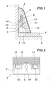
- the holder 1 for a closing strip 2 has a wall leg 4 that can be fastened to a wall 3 and a support leg 5 protruding therefrom, which is supported on a floor covering 7 laid on the base 6.
- the wall leg 4 forms a bent, upwardly projecting, toothed holding web 8, which cooperates with a downwardly open groove 9 of the end strip 2.
- the holder 4 forms two additional securing tongues 10 which engage with a hook-shaped locking projection 11 a securing stop 12 of the end strip 2, as the Fig. 1 can be removed.
- This securing stop 12 can be formed by a wall of a groove 13, but this is not mandatory because it is only important that to prevent the unintentional removal of the end strip 2 from the retaining web 8, for which a transverse to the retaining web 8 extending locking stop 12 is required, which is overlapped by the securing tongue 10.
- the end strip 2 After attaching the bracket 1 to the wall 3, preferably by means of screws, for which 4 long holes 14 are provided in the wall leg, the end strip 2 can be plugged wall parallel to the retaining bar 8, wherein the resilient locking tabs 10 via one of the end strip. 2 formed contact surface 15 are swung out to overlap in the drawn mounting position the safety stop 12.
- the end strip 2, which experiences a conventional clamp on the retaining web 8 in the groove 9 is thus secured by the resilient locking tongues 10 against unintentional removal from the retaining web 8 and learns through the securing tabs 10 an additional support, so that the system of the end strip 2 both is ensured on the wall 3 and the floor covering 7.
- the embodiment of the Fig. 3 is different from the after Fig. 1 especially by the arrangement of the securing tongues 10, which are not provided on the wall leg 4, but on the support leg 5. Because of the arrangement of the securing tabs 10 in the region of the support leg 5 remains between the bracket 1 and the end strip 2 sufficient space for a cable or cable routing, as shown in the Fig. 3 indicated by dash-dotted lines. Accordingly, the locking stop 12 forming groove 13 is displaced in the end strip 2. The function of the locking tongues 10 remains, however, because they prevent the system by the backup stop 12, the removal of the end strip 2 from the holding web 8.
- a comparable space for a cable or cable installation is created by the approximately in the direction of the retaining web 8 extending leg of the locking tabs 10 protrudes in the opposite direction to the retaining web 8 of the bend for the retaining web 8 down and engages with the locking projection 11 in the groove 13.
- this securing the end strip 2 makes a release of the end strip 2 from the holding web 8 without breaking the securing tabs 10 impossible.
- the resilient locking tongues 10 are arranged on the retaining web 8 itself and engage with its locking projection 11 in an extension 16 of the retaining web 8 receiving groove 9, which in turn results in a transverse to the retaining web 8 extending locking stop 12.
- the securing tongues 10 prevent inadvertent removal of the end strip 2 from the retaining web 8, but they can hardly make a contribution to the better support and support the end strip 2.
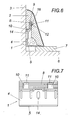
- a holder 1 receiving the bottom part 17 is provided, which engages under the floor covering 7 and is therefore held by the floor covering 7 on the ground 6.
- a leaf spring 19 inserted in a receptacle 18, which is supported on the end face of the floor covering 7 under bias, the bottom part 17 is pressed against the wall 3.
- the bottom part 17 forms on both sides of the receptacle 18 for the leaf spring 19 plug-in guides 20 for mating projections 21, which extend the wall leg 4 of the holder 1 down and form toothed racks to reach within the plug guides 20 against an unintentional withdrawal of the holder 1 sufficient clamping fit.
- the holder 1 is inserted with its insertion lugs 21 to the placement of the support leg 5 on the floor covering 7 in the plug-in guides 20, whereby the attachment of the holder 1 is completed by itself. It only needs the end strip 2 to be pushed onto the retaining web 8, in turn, locking tongues 10 prevent the unintentional removal of the end strip 2 from the retaining web 8.
- the securing tongues 10 are arranged in this embodiment in the region of the wall leg 4, as the Fig. 8 can be removed.
Landscapes
- Architecture (AREA)
- Engineering & Computer Science (AREA)
- Civil Engineering (AREA)
- Structural Engineering (AREA)
- Floor Finish (AREA)
- Installation Of Indoor Wiring (AREA)
- Clamps And Clips (AREA)
- Furniture Connections (AREA)
- Mirrors, Picture Frames, Photograph Stands, And Related Fastening Devices (AREA)
- Details Of Indoor Wiring (AREA)
- Coating With Molten Metal (AREA)
- Soil Working Implements (AREA)
- Auxiliary Devices For And Details Of Packaging Control (AREA)
Priority Applications (3)
| Application Number | Priority Date | Filing Date | Title |
|---|---|---|---|
| PL09450172T PL2169143T3 (pl) | 2008-09-25 | 2009-09-16 | Urządzenie do mocowania listwy maskującej |
| SI200931653A SI2169143T1 (sl) | 2008-09-25 | 2009-09-16 | Naprava za pritrditev zaključne letve |
| HRP20170681TT HRP20170681T1 (hr) | 2008-09-25 | 2017-05-05 | Uređaj za pričvršćivanje završne lajsne |
Applications Claiming Priority (1)
| Application Number | Priority Date | Filing Date | Title |
|---|---|---|---|
| AT0149508A AT507336B1 (de) | 2008-09-25 | 2008-09-25 | Vorrichtung zur befestigung einer abschlussleiste |
Publications (3)
| Publication Number | Publication Date |
|---|---|
| EP2169143A2 true EP2169143A2 (fr) | 2010-03-31 |
| EP2169143A3 EP2169143A3 (fr) | 2012-04-18 |
| EP2169143B1 EP2169143B1 (fr) | 2017-02-15 |
Family
ID=41467224
Family Applications (1)
| Application Number | Title | Priority Date | Filing Date |
|---|---|---|---|
| EP09450172.3A Active EP2169143B1 (fr) | 2008-09-25 | 2009-09-16 | Dispositif de fixation d'une baguette de bord |
Country Status (15)
| Country | Link |
|---|---|
| US (1) | US8171698B2 (fr) |
| EP (1) | EP2169143B1 (fr) |
| CN (2) | CN104727535A (fr) |
| AT (1) | AT507336B1 (fr) |
| CA (1) | CA2680619C (fr) |
| DE (1) | DE202009019070U1 (fr) |
| DK (1) | DK2169143T3 (fr) |
| ES (1) | ES2624781T3 (fr) |
| HR (1) | HRP20170681T1 (fr) |
| HU (1) | HUE032616T2 (fr) |
| LT (1) | LT2169143T (fr) |
| PL (1) | PL2169143T3 (fr) |
| PT (1) | PT2169143T (fr) |
| RU (1) | RU2494203C2 (fr) |
| SI (1) | SI2169143T1 (fr) |
Cited By (7)
| Publication number | Priority date | Publication date | Assignee | Title |
|---|---|---|---|---|
| WO2013124005A1 (fr) | 2012-02-23 | 2013-08-29 | Kaindl Flooring Gmbh | Procédé de montage sans vis d'une baguette de finition, porte-baguette de finition, destiné en particulier à être utilisé avec ledit procédé de montage, et combinaison d'une baguette de finition et d'au moins un porte-baguette de finition |
| WO2016007978A1 (fr) | 2014-07-18 | 2016-01-21 | Neuhofer Jun Franz | Dispositif de fixation d'une baguette de bord sur un mur |
| WO2017152199A1 (fr) * | 2016-03-08 | 2017-09-14 | Neuhofer Jun Franz | Dispositif de finition pour un plancher |
| WO2017175121A1 (fr) * | 2016-04-05 | 2017-10-12 | Adam Galas | Élément de fixation élastique, et système de fixation de plinthe comprenant une plinthe et un tel élément de fixation |
| WO2019000004A1 (fr) | 2017-06-26 | 2019-01-03 | Franz Neuhofer | Dispositif permettant de fixer une baguette de bord |
| WO2022073045A1 (fr) | 2020-10-06 | 2022-04-14 | Franz Neuhofer | Dispositif pour fixer une baguette de finition |
| RU2824486C1 (ru) * | 2020-10-06 | 2024-08-08 | Франц НОЙХОФЕР | Устройство для закрепления плинтуса |
Families Citing this family (23)
| Publication number | Priority date | Publication date | Assignee | Title |
|---|---|---|---|---|
| US20070251167A1 (en) * | 2006-04-28 | 2007-11-01 | Multilink, Inc. | Cable and overlay moldings |
| US20090293392A1 (en) * | 2008-05-22 | 2009-12-03 | Tim Dykstra | Moulding Assembly |
| WO2013006975A2 (fr) * | 2011-07-11 | 2013-01-17 | Cory Halischuk | Fixation d'une garniture de plafond |
| AT512046B1 (de) * | 2012-01-09 | 2013-05-15 | Neuhofer Franz Jun | Vorrichtung zum überbrücken der anschlussfuge zwischen einer wand und einem bodenbelag |
| US9803352B2 (en) * | 2012-06-11 | 2017-10-31 | Dirtt Environmental Solutions, Ltd | Trim connection systems and methods |
| US8973321B2 (en) * | 2013-03-15 | 2015-03-10 | Tarkett Usa Inc. | Two-part molding system |
| AT513740B1 (de) * | 2013-03-21 | 2014-07-15 | Neuhofer Franz Jun | Vorrichtung zum Befestigen eines Deckenprofils |
| US9027299B2 (en) * | 2013-07-12 | 2015-05-12 | Joseph Mea | Themed modular ceiling and wall decor kit and system |
| CA2832135A1 (fr) * | 2013-11-28 | 2015-05-28 | Goodheart, Sheldon | Procede et systeme de moulure de garnissage |
| DE102015112456A1 (de) * | 2014-10-09 | 2016-04-14 | Fischer Italia S.R.L. | Bodenstehendes Sanitärobjekt mit zwei Befestigern |
| US10676941B1 (en) * | 2015-01-29 | 2020-06-09 | Jeremy P. Hoffman | Wall-attachment structure and system employing an intra-structural hinge for reinforcing preferred placement on a straight or curved wall |
| US9903125B2 (en) * | 2015-01-29 | 2018-02-27 | Jeremy P. Hoffman | System and method for installation of crown molding on imperfect walls |
| DE102015104812A1 (de) * | 2015-03-27 | 2016-09-29 | Tilo Gmbh | Bausatz zum Befestigen einer Abschlussleiste an einem Baukörper, ein Befestigungsprofil und eine Abschlussleiste |
| DE202017102750U1 (de) | 2017-02-17 | 2017-06-07 | Engeltech Gmbh | Vorrichtung zur werkzeuglosen Montage einer Abschlussleiste |
| RU181728U1 (ru) * | 2018-04-11 | 2018-07-26 | Алексей Александрович Маркин | Скоба для монтажа плинтуса |
| RU184802U1 (ru) * | 2018-06-15 | 2018-11-09 | Гудков Александр Владимирович | Внутренний профиль погонажного изделия |
| DE102018119959A1 (de) * | 2018-08-16 | 2020-02-20 | Kgm Holzerzeugnisse Gmbh | Vorrichtung zur werkzeuglosen Montage einer Abschlussleiste |
| RU184567U1 (ru) * | 2018-09-04 | 2018-10-30 | Сергей Станиславович Кузнецов | Устройство крепления облицовочного элемента в месте сопряжения двух поверхностей |
| CN112554479B (zh) * | 2019-09-25 | 2022-09-09 | 和能人居科技(天津)集团股份有限公司 | 连接组件及墙板组件 |
| WO2021108385A1 (fr) * | 2019-11-26 | 2021-06-03 | Mcs Industries, Inc. | Système de gestion de câble |
| DE202020101320U1 (de) | 2020-03-10 | 2021-06-11 | Wolfgang Engel | Montageclip für Sockelleisten mit wandseitiger Sperrfunktion |
| DE202020101330U1 (de) | 2020-03-11 | 2021-06-15 | Wolfgang Engel | Montageclip für Sockelleisten mit bodenbelagseitiger Sperrfunktion |
| AT524434B1 (de) * | 2021-02-01 | 2022-06-15 | Franz Neuhofer | Vorrichtung zur Befestigung einer Abschlussleiste |
Citations (2)
| Publication number | Priority date | Publication date | Assignee | Title |
|---|---|---|---|---|
| DE10107866A1 (de) | 2001-02-20 | 2001-09-20 | Ernst Ruesch Gmbh | Abdeckleiste und Halteelement dafür |
| WO2002066764A2 (fr) | 2001-02-20 | 2002-08-29 | Malgorzata Wesolowska | Plinthe comprenant des elements de finition |
Family Cites Families (20)
| Publication number | Priority date | Publication date | Assignee | Title |
|---|---|---|---|---|
| SU141284A1 (ru) * | 1961-03-17 | 1961-11-30 | В.В. Чарнолусский | Плинтус |
| US3298147A (en) * | 1964-07-17 | 1967-01-17 | Haberman Painting & Decorating | Detachable building trim |
| AT397698B (de) | 1992-03-12 | 1994-06-27 | Kaindl Holzindustrie | Halter |
| US6148883A (en) * | 1993-03-22 | 2000-11-21 | Wilson; Bryan Alexander | Wood trim system |
| DE19511360A1 (de) * | 1994-05-09 | 1995-11-16 | Wolf Dietrich Stoellner | Deckleiste für Maueranschlüsse, Flachdächer und dergleichen |
| DE29716146U1 (de) | 1997-09-09 | 1997-11-20 | W. Döllken & Co. GmbH, 45239 Essen | Vorrichtung zum Befestigen von Abschlußleisten |
| CN2361732Y (zh) * | 1998-06-08 | 2000-02-02 | 李清吉 | 踢脚板 |
| US6381915B1 (en) * | 1999-01-19 | 2002-05-07 | Selectrim Corporation | Architectural molding and mounting device therefor |
| JP3490674B2 (ja) * | 2000-09-20 | 2004-01-26 | ニチハ株式会社 | 外壁施工構造 |
| DE10052802A1 (de) * | 2000-10-25 | 2002-06-20 | Huelsta Werke Huels Kg | Vielseitig handhabbare Funktionsleiste für Raumwandungen, insbesondere Raumecken |
| KR100378557B1 (ko) * | 2000-11-07 | 2003-04-08 | 문영석 | 선박 벽면 하단부의 걸레받이 장착구조 |
| UA66192C2 (en) * | 2001-02-20 | 2006-07-17 | Plinth with end elements | |
| DE10107864C2 (de) * | 2001-02-20 | 2003-06-12 | Ernst Ruesch Gmbh | Halteelement für Abdeckleisten |
| US6729087B2 (en) * | 2002-01-25 | 2004-05-04 | Mark J. Sauter | Two-part separable base molding |
| DE20301213U1 (de) * | 2003-01-27 | 2003-04-24 | Tilo Gmbh, Lohnsburg | Anschlussleiste |
| FR2863288A1 (fr) * | 2003-12-08 | 2005-06-10 | Bernard Francois Michel Proot | Plinthe multi fonction demontable |
| CH694891A5 (fr) * | 2004-05-05 | 2005-08-31 | Gerard Savary Ebenisterie Agen | Piece de fixation pour un element de menuiserie, notamment une plinthe en bois, avec passage pour cables integre. |
| AT503228B1 (de) | 2004-05-26 | 2009-02-15 | Neuhofer Franz Jun | Vorrichtung zur befestigung einer abschlussleiste |
| DE202005005425U1 (de) * | 2005-04-05 | 2005-06-16 | Karl Pedross Ag | Vorrichtung zum Befestigen von Abschlußleisten |
| AT9910U1 (de) * | 2006-12-07 | 2008-05-15 | Neuhofer Franz Jun | Vorrichtung zum befestigen einer genuteten sockelleiste an einer wand |
-
2008
- 2008-09-25 AT AT0149508A patent/AT507336B1/de not_active IP Right Cessation
-
2009
- 2009-09-16 PT PT94501723T patent/PT2169143T/pt unknown
- 2009-09-16 LT LTEP09450172.3T patent/LT2169143T/lt unknown
- 2009-09-16 EP EP09450172.3A patent/EP2169143B1/fr active Active
- 2009-09-16 DK DK09450172.3T patent/DK2169143T3/en active
- 2009-09-16 PL PL09450172T patent/PL2169143T3/pl unknown
- 2009-09-16 ES ES09450172.3T patent/ES2624781T3/es active Active
- 2009-09-16 DE DE202009019070.6U patent/DE202009019070U1/de not_active Expired - Lifetime
- 2009-09-16 HU HUE09450172A patent/HUE032616T2/en unknown
- 2009-09-16 SI SI200931653A patent/SI2169143T1/sl unknown
- 2009-09-24 CA CA2680619A patent/CA2680619C/fr active Active
- 2009-09-24 RU RU2009135630/03A patent/RU2494203C2/ru active
- 2009-09-24 US US12/586,594 patent/US8171698B2/en active Active
- 2009-09-25 CN CN201510144431.XA patent/CN104727535A/zh active Pending
- 2009-09-25 CN CN200910221461A patent/CN101725243A/zh active Pending
-
2017
- 2017-05-05 HR HRP20170681TT patent/HRP20170681T1/hr unknown
Patent Citations (2)
| Publication number | Priority date | Publication date | Assignee | Title |
|---|---|---|---|---|
| DE10107866A1 (de) | 2001-02-20 | 2001-09-20 | Ernst Ruesch Gmbh | Abdeckleiste und Halteelement dafür |
| WO2002066764A2 (fr) | 2001-02-20 | 2002-08-29 | Malgorzata Wesolowska | Plinthe comprenant des elements de finition |
Cited By (12)
| Publication number | Priority date | Publication date | Assignee | Title |
|---|---|---|---|---|
| WO2013124005A1 (fr) | 2012-02-23 | 2013-08-29 | Kaindl Flooring Gmbh | Procédé de montage sans vis d'une baguette de finition, porte-baguette de finition, destiné en particulier à être utilisé avec ledit procédé de montage, et combinaison d'une baguette de finition et d'au moins un porte-baguette de finition |
| DE102012202795A1 (de) | 2012-02-23 | 2013-08-29 | Kaindl Flooring Gmbh | Verfahren zum schraubenlosen Montieren einer Abschlussleiste und Abschlussleistenhalter, insbesondere zur Verwendung bei diesem Montageverfahren |
| WO2016007978A1 (fr) | 2014-07-18 | 2016-01-21 | Neuhofer Jun Franz | Dispositif de fixation d'une baguette de bord sur un mur |
| WO2017152199A1 (fr) * | 2016-03-08 | 2017-09-14 | Neuhofer Jun Franz | Dispositif de finition pour un plancher |
| WO2017175121A1 (fr) * | 2016-04-05 | 2017-10-12 | Adam Galas | Élément de fixation élastique, et système de fixation de plinthe comprenant une plinthe et un tel élément de fixation |
| CN108884681A (zh) * | 2016-04-05 | 2018-11-23 | 亚当·加拉斯 | 弹性固定元件以及包括其和踢脚板的踢脚板固定系统 |
| US10774546B2 (en) | 2016-04-05 | 2020-09-15 | Adam Galas | Resilient fixing element and a skirting board fixing system comprising a skirting board and such a fixing element |
| CN108884681B (zh) * | 2016-04-05 | 2020-11-27 | 亚当·加拉斯 | 弹性固定元件以及包括其和踢脚板的踢脚板固定系统 |
| WO2019000004A1 (fr) | 2017-06-26 | 2019-01-03 | Franz Neuhofer | Dispositif permettant de fixer une baguette de bord |
| WO2022073045A1 (fr) | 2020-10-06 | 2022-04-14 | Franz Neuhofer | Dispositif pour fixer une baguette de finition |
| RU2824486C1 (ru) * | 2020-10-06 | 2024-08-08 | Франц НОЙХОФЕР | Устройство для закрепления плинтуса |
| US12442200B2 (en) | 2020-10-06 | 2025-10-14 | Franz Neuhofer | Device for fastening a finishing strip |
Also Published As
| Publication number | Publication date |
|---|---|
| HRP20170681T1 (hr) | 2017-07-14 |
| US8171698B2 (en) | 2012-05-08 |
| ES2624781T3 (es) | 2017-07-17 |
| SI2169143T1 (sl) | 2017-06-30 |
| AT507336A1 (de) | 2010-04-15 |
| PL2169143T3 (pl) | 2017-10-31 |
| LT2169143T (lt) | 2017-05-10 |
| CA2680619C (fr) | 2015-11-24 |
| RU2009135630A (ru) | 2011-03-27 |
| US20100071288A1 (en) | 2010-03-25 |
| CA2680619A1 (fr) | 2010-03-25 |
| CN104727535A (zh) | 2015-06-24 |
| AT507336B1 (de) | 2010-07-15 |
| RU2494203C2 (ru) | 2013-09-27 |
| DE202009019070U1 (de) | 2016-03-10 |
| DK2169143T3 (en) | 2017-05-22 |
| HUE032616T2 (en) | 2017-10-30 |
| EP2169143B1 (fr) | 2017-02-15 |
| EP2169143A3 (fr) | 2012-04-18 |
| CN101725243A (zh) | 2010-06-09 |
| PT2169143T (pt) | 2017-05-03 |
Similar Documents
| Publication | Publication Date | Title |
|---|---|---|
| EP2169143B1 (fr) | Dispositif de fixation d'une baguette de bord | |
| DE10107864C2 (de) | Halteelement für Abdeckleisten | |
| DE202010012567U1 (de) | Seilumlenkstück für einen Seilfensterheber | |
| WO2013056282A1 (fr) | Dispositif d'assemblage de deux éléments de paroi de tiroir à disposer à angle droit | |
| DE202009017854U1 (de) | Duschrinnenanordnung für Wandeinbau | |
| EP0329843B1 (fr) | Boîtier pour appareil électrique | |
| AT503228B1 (de) | Vorrichtung zur befestigung einer abschlussleiste | |
| WO2009030334A2 (fr) | Dispositif de fixation d'un appendice sur un support | |
| EP1954900A1 (fr) | Dispositif de fixation d'un profile de recouvrement qui assure la transition ente deux surfaces perpendiculaires l'une a l'autre | |
| EP0649617B1 (fr) | Dispositif de fixation notamment pour plinthes pour socles d'armoire | |
| AT513026A4 (de) | Vorrichtung zum Überbrücken der Anschlussfuge zwischen einer Wand und einem Bodenbelag | |
| EP1930525A2 (fr) | Dispositif de fixation d'une plinthe rainurée sur un mur | |
| EP2742195B1 (fr) | Procédé de montage sans vis d'une baguette de finition | |
| EP2538507B1 (fr) | Adaptateur de barre collectrice | |
| AT513740B1 (de) | Vorrichtung zum Befestigen eines Deckenprofils | |
| EP1930527A2 (fr) | Dispositif de fixation d'une plinthe rainurée sur le mur | |
| EP3095949A1 (fr) | Dispositif de fixation d'un boîtier d'une plinthe d'étanchéité | |
| EP2961997B1 (fr) | Partie de support destinée à la fixation d'objets allongés, partie formant étrier destinée à être montée sur une plaque de support et ensemble pourvu d'une partie de support et d'une partie formant étrier | |
| DE102015113048B4 (de) | Fahrzeugsitz | |
| DE102014109456A1 (de) | Halterungsvorrichtung | |
| AT523631B1 (de) | Vorrichtung zur Befestigung einer Abschlussleiste | |
| DE10306797B3 (de) | Vorrichtung zur Montage eines elektrischen Geräts an einer Wand oder dergleichen | |
| DE19651151C1 (de) | Verankerungseinheit zum Aufstecken auf eine Montageschiene | |
| AT501584B1 (de) | Anschluss- oder geräteadapter | |
| DE20114555U1 (de) | Ankerwinkel |
Legal Events
| Date | Code | Title | Description |
|---|---|---|---|
| PUAI | Public reference made under article 153(3) epc to a published international application that has entered the european phase |
Free format text: ORIGINAL CODE: 0009012 |
|
| AK | Designated contracting states |
Kind code of ref document: A2 Designated state(s): AT BE BG CH CY CZ DE DK EE ES FI FR GB GR HR HU IE IS IT LI LT LU LV MC MK MT NL NO PL PT RO SE SI SK SM TR |
|
| AX | Request for extension of the european patent |
Extension state: AL BA RS |
|
| PUAL | Search report despatched |
Free format text: ORIGINAL CODE: 0009013 |
|
| AK | Designated contracting states |
Kind code of ref document: A3 Designated state(s): AT BE BG CH CY CZ DE DK EE ES FI FR GB GR HR HU IE IS IT LI LT LU LV MC MK MT NL NO PL PT RO SE SI SK SM TR |
|
| AX | Request for extension of the european patent |
Extension state: AL BA RS |
|
| RIC1 | Information provided on ipc code assigned before grant |
Ipc: E04F 19/04 20060101AFI20120314BHEP |
|
| 17P | Request for examination filed |
Effective date: 20121015 |
|
| 17Q | First examination report despatched |
Effective date: 20140530 |
|
| GRAP | Despatch of communication of intention to grant a patent |
Free format text: ORIGINAL CODE: EPIDOSNIGR1 |
|
| INTG | Intention to grant announced |
Effective date: 20160920 |
|
| GRAS | Grant fee paid |
Free format text: ORIGINAL CODE: EPIDOSNIGR3 |
|
| GRAA | (expected) grant |
Free format text: ORIGINAL CODE: 0009210 |
|
| AK | Designated contracting states |
Kind code of ref document: B1 Designated state(s): AT BE BG CH CY CZ DE DK EE ES FI FR GB GR HR HU IE IS IT LI LT LU LV MC MK MT NL NO PL PT RO SE SI SK SM TR |
|
| REG | Reference to a national code |
Ref country code: GB Ref legal event code: FG4D Free format text: NOT ENGLISH Ref country code: CH Ref legal event code: EP |
|
| REG | Reference to a national code |
Ref country code: IE Ref legal event code: FG4D Free format text: LANGUAGE OF EP DOCUMENT: GERMAN |
|
| REG | Reference to a national code |
Ref country code: AT Ref legal event code: REF Ref document number: 867997 Country of ref document: AT Kind code of ref document: T Effective date: 20170315 |
|
| REG | Reference to a national code |
Ref country code: DE Ref legal event code: R096 Ref document number: 502009013645 Country of ref document: DE |
|
| REG | Reference to a national code |
Ref country code: CH Ref legal event code: NV Representative=s name: E. BLUM AND CO. AG PATENT- UND MARKENANWAELTE , CH |
|
| REG | Reference to a national code |
Ref country code: DE Ref legal event code: R082 Ref document number: 502009013645 Country of ref document: DE Representative=s name: WOLF & WOLF PATENT- UND RECHTSANWALTSGESELLSCH, DE |
|
| REG | Reference to a national code |
Ref country code: PT Ref legal event code: SC4A Ref document number: 2169143 Country of ref document: PT Date of ref document: 20170503 Kind code of ref document: T Free format text: AVAILABILITY OF NATIONAL TRANSLATION Effective date: 20170424 Ref country code: NL Ref legal event code: FP |
|
| REG | Reference to a national code |
Ref country code: HR Ref legal event code: TUEP Ref document number: P20170681 Country of ref document: HR |
|
| REG | Reference to a national code |
Ref country code: RO Ref legal event code: EPE |
|
| REG | Reference to a national code |
Ref country code: DK Ref legal event code: T3 Effective date: 20170518 |
|
| REG | Reference to a national code |
Ref country code: SE Ref legal event code: TRGR |
|
| REG | Reference to a national code |
Ref country code: NO Ref legal event code: T2 Effective date: 20170215 |
|
| REG | Reference to a national code |
Ref country code: HR Ref legal event code: T1PR Ref document number: P20170681 Country of ref document: HR |
|
| REG | Reference to a national code |
Ref country code: EE Ref legal event code: FG4A Ref document number: E013809 Country of ref document: EE Effective date: 20170512 Ref country code: ES Ref legal event code: FG2A Ref document number: 2624781 Country of ref document: ES Kind code of ref document: T3 Effective date: 20170717 |
|
| PG25 | Lapsed in a contracting state [announced via postgrant information from national office to epo] |
Ref country code: GR Free format text: LAPSE BECAUSE OF FAILURE TO SUBMIT A TRANSLATION OF THE DESCRIPTION OR TO PAY THE FEE WITHIN THE PRESCRIBED TIME-LIMIT Effective date: 20170516 |
|
| REG | Reference to a national code |
Ref country code: FR Ref legal event code: PLFP Year of fee payment: 9 |
|
| REG | Reference to a national code |
Ref country code: HU Ref legal event code: AG4A Ref document number: E032616 Country of ref document: HU |
|
| REG | Reference to a national code |
Ref country code: SK Ref legal event code: T3 Ref document number: E 24275 Country of ref document: SK |
|
| REG | Reference to a national code |
Ref country code: DE Ref legal event code: R097 Ref document number: 502009013645 Country of ref document: DE |
|
| PG25 | Lapsed in a contracting state [announced via postgrant information from national office to epo] |
Ref country code: SM Free format text: LAPSE BECAUSE OF FAILURE TO SUBMIT A TRANSLATION OF THE DESCRIPTION OR TO PAY THE FEE WITHIN THE PRESCRIBED TIME-LIMIT Effective date: 20170215 |
|
| PLBE | No opposition filed within time limit |
Free format text: ORIGINAL CODE: 0009261 |
|
| STAA | Information on the status of an ep patent application or granted ep patent |
Free format text: STATUS: NO OPPOSITION FILED WITHIN TIME LIMIT |
|
| 26N | No opposition filed |
Effective date: 20171116 |
|
| PG25 | Lapsed in a contracting state [announced via postgrant information from national office to epo] |
Ref country code: MC Free format text: LAPSE BECAUSE OF FAILURE TO SUBMIT A TRANSLATION OF THE DESCRIPTION OR TO PAY THE FEE WITHIN THE PRESCRIBED TIME-LIMIT Effective date: 20170215 |
|
| REG | Reference to a national code |
Ref country code: IE Ref legal event code: MM4A |
|
| PG25 | Lapsed in a contracting state [announced via postgrant information from national office to epo] |
Ref country code: LU Free format text: LAPSE BECAUSE OF NON-PAYMENT OF DUE FEES Effective date: 20170916 |
|
| PG25 | Lapsed in a contracting state [announced via postgrant information from national office to epo] |
Ref country code: IE Free format text: LAPSE BECAUSE OF NON-PAYMENT OF DUE FEES Effective date: 20170916 |
|
| PG25 | Lapsed in a contracting state [announced via postgrant information from national office to epo] |
Ref country code: MT Free format text: LAPSE BECAUSE OF FAILURE TO SUBMIT A TRANSLATION OF THE DESCRIPTION OR TO PAY THE FEE WITHIN THE PRESCRIBED TIME-LIMIT Effective date: 20170215 |
|
| REG | Reference to a national code |
Ref country code: FR Ref legal event code: PLFP Year of fee payment: 10 |
|
| REG | Reference to a national code |
Ref country code: HR Ref legal event code: ODRP Ref document number: P20170681 Country of ref document: HR Payment date: 20190909 Year of fee payment: 11 |
|
| PG25 | Lapsed in a contracting state [announced via postgrant information from national office to epo] |
Ref country code: CY Free format text: LAPSE BECAUSE OF NON-PAYMENT OF DUE FEES Effective date: 20170215 |
|
| PG25 | Lapsed in a contracting state [announced via postgrant information from national office to epo] |
Ref country code: MK Free format text: LAPSE BECAUSE OF FAILURE TO SUBMIT A TRANSLATION OF THE DESCRIPTION OR TO PAY THE FEE WITHIN THE PRESCRIBED TIME-LIMIT Effective date: 20170215 |
|
| PG25 | Lapsed in a contracting state [announced via postgrant information from national office to epo] |
Ref country code: IS Free format text: LAPSE BECAUSE OF FAILURE TO SUBMIT A TRANSLATION OF THE DESCRIPTION OR TO PAY THE FEE WITHIN THE PRESCRIBED TIME-LIMIT Effective date: 20170615 |
|
| REG | Reference to a national code |
Ref country code: HR Ref legal event code: ODRP Ref document number: P20170681 Country of ref document: HR Payment date: 20200903 Year of fee payment: 12 |
|
| REG | Reference to a national code |
Ref country code: HR Ref legal event code: ODRP Ref document number: P20170681 Country of ref document: HR Payment date: 20210831 Year of fee payment: 13 |
|
| REG | Reference to a national code |
Ref country code: HR Ref legal event code: ODRP Ref document number: P20170681 Country of ref document: HR Payment date: 20220831 Year of fee payment: 14 |
|
| P01 | Opt-out of the competence of the unified patent court (upc) registered |
Effective date: 20230504 |
|
| REG | Reference to a national code |
Ref country code: HR Ref legal event code: ODRP Ref document number: P20170681 Country of ref document: HR Payment date: 20230904 Year of fee payment: 15 |
|
| REG | Reference to a national code |
Ref country code: HR Ref legal event code: ODRP Ref document number: P20170681 Country of ref document: HR Payment date: 20240904 Year of fee payment: 16 |
|
| REG | Reference to a national code |
Ref country code: HR Ref legal event code: ODRP Ref document number: P20170681 Country of ref document: HR Payment date: 20250827 Year of fee payment: 17 |
|
| REG | Reference to a national code |
Ref country code: CH Ref legal event code: U11 Free format text: ST27 STATUS EVENT CODE: U-0-0-U10-U11 (AS PROVIDED BY THE NATIONAL OFFICE) Effective date: 20251001 |
|
| PGFP | Annual fee paid to national office [announced via postgrant information from national office to epo] |
Ref country code: PT Payment date: 20250826 Year of fee payment: 17 Ref country code: FI Payment date: 20250925 Year of fee payment: 17 |
|
| PGFP | Annual fee paid to national office [announced via postgrant information from national office to epo] |
Ref country code: LT Payment date: 20250827 Year of fee payment: 17 Ref country code: DK Payment date: 20250924 Year of fee payment: 17 Ref country code: DE Payment date: 20250826 Year of fee payment: 17 |
|
| PGFP | Annual fee paid to national office [announced via postgrant information from national office to epo] |
Ref country code: NO Payment date: 20250917 Year of fee payment: 17 |
|
| PGFP | Annual fee paid to national office [announced via postgrant information from national office to epo] |
Ref country code: TR Payment date: 20250828 Year of fee payment: 17 Ref country code: PL Payment date: 20250822 Year of fee payment: 17 Ref country code: NL Payment date: 20250925 Year of fee payment: 17 Ref country code: IT Payment date: 20250922 Year of fee payment: 17 |
|
| PGFP | Annual fee paid to national office [announced via postgrant information from national office to epo] |
Ref country code: BE Payment date: 20250925 Year of fee payment: 17 Ref country code: BG Payment date: 20250925 Year of fee payment: 17 Ref country code: HU Payment date: 20250904 Year of fee payment: 17 Ref country code: GB Payment date: 20250825 Year of fee payment: 17 |
|
| PGFP | Annual fee paid to national office [announced via postgrant information from national office to epo] |
Ref country code: HR Payment date: 20250827 Year of fee payment: 17 |
|
| PGFP | Annual fee paid to national office [announced via postgrant information from national office to epo] |
Ref country code: FR Payment date: 20250925 Year of fee payment: 17 Ref country code: AT Payment date: 20250826 Year of fee payment: 17 |
|
| PGFP | Annual fee paid to national office [announced via postgrant information from national office to epo] |
Ref country code: SE Payment date: 20250924 Year of fee payment: 17 |
|
| PGFP | Annual fee paid to national office [announced via postgrant information from national office to epo] |
Ref country code: CZ Payment date: 20250828 Year of fee payment: 17 Ref country code: EE Payment date: 20250926 Year of fee payment: 17 |
|
| PGFP | Annual fee paid to national office [announced via postgrant information from national office to epo] |
Ref country code: RO Payment date: 20250904 Year of fee payment: 17 |
|
| PGFP | Annual fee paid to national office [announced via postgrant information from national office to epo] |
Ref country code: SK Payment date: 20250901 Year of fee payment: 17 |
|
| PGFP | Annual fee paid to national office [announced via postgrant information from national office to epo] |
Ref country code: LV Payment date: 20250922 Year of fee payment: 17 |
|
| PGFP | Annual fee paid to national office [announced via postgrant information from national office to epo] |
Ref country code: SI Payment date: 20250826 Year of fee payment: 17 |
|
| PGFP | Annual fee paid to national office [announced via postgrant information from national office to epo] |
Ref country code: CH Payment date: 20251001 Year of fee payment: 17 |
|
| PGFP | Annual fee paid to national office [announced via postgrant information from national office to epo] |
Ref country code: ES Payment date: 20251015 Year of fee payment: 17 |