EP2169181A2 - Gasturbinenrotor und zugehöriges Auswuchtgewicht - Google Patents
Gasturbinenrotor und zugehöriges Auswuchtgewicht Download PDFInfo
- Publication number
- EP2169181A2 EP2169181A2 EP09171326A EP09171326A EP2169181A2 EP 2169181 A2 EP2169181 A2 EP 2169181A2 EP 09171326 A EP09171326 A EP 09171326A EP 09171326 A EP09171326 A EP 09171326A EP 2169181 A2 EP2169181 A2 EP 2169181A2
- Authority
- EP
- European Patent Office
- Prior art keywords
- balance weight
- rear wall
- projection
- flange
- turbine rotor
- Prior art date
- Legal status (The legal status is an assumption and is not a legal conclusion. Google has not performed a legal analysis and makes no representation as to the accuracy of the status listed.)
- Granted
Links
Images


Classifications
-
- F—MECHANICAL ENGINEERING; LIGHTING; HEATING; WEAPONS; BLASTING
- F01—MACHINES OR ENGINES IN GENERAL; ENGINE PLANTS IN GENERAL; STEAM ENGINES
- F01D—NON-POSITIVE DISPLACEMENT MACHINES OR ENGINES, e.g. STEAM TURBINES
- F01D5/00—Blades; Blade-carrying members; Heating, heat-insulating, cooling or antivibration means on the blades or the members
- F01D5/02—Blade-carrying members, e.g. rotors
- F01D5/027—Arrangements for balancing
-
- F—MECHANICAL ENGINEERING; LIGHTING; HEATING; WEAPONS; BLASTING
- F01—MACHINES OR ENGINES IN GENERAL; ENGINE PLANTS IN GENERAL; STEAM ENGINES
- F01D—NON-POSITIVE DISPLACEMENT MACHINES OR ENGINES, e.g. STEAM TURBINES
- F01D11/00—Preventing or minimising internal leakage of working-fluid, e.g. between stages
- F01D11/001—Preventing or minimising internal leakage of working-fluid, e.g. between stages for sealing space between stator blade and rotor
Definitions
- This invention relates to the balancing of turbine rotors in gas turbine engines, and, more particularly, to boltless balance weights for rotor disks of such engines.
- Gas turbine engines include one or more rotors comprising a disk carrying a plurality of airfoil-shaped turbine blades which extract energy from combustion gases. Because of the high rotational speeds of the disks and the large disk and blade masses, proper balancing of the rotors of the turbine is important. Unbalance may, in some cases, seriously affect the rotating assembly bearings and engine operation.
- One known method of balancing a rotor disk is to provide the disk with dedicated balance planes incorporating extra material. These can be selectively ground away as needed. However, this process is difficult to implement efficiently and with repeatable results.
- Another known method for balancing turbine disks is to add washers or other weights to select bolted joints of the rotors.
- the number, position, and mass of the weighted washers needed to balance the disk is dependent on the balance characteristics of each turbine disk being balanced. These balance characteristics are determined by a balance test on each rotor. After finding the unbalance of a turbine rotor, the weighted washers are added to designated bolted joints until the rotor is balanced. While this method works well for turbine rotors with bolted joints, not all turbine rotors have such joints.
- a balance weight for a rotor includes: (a) an arcuate body including a front wall and a rear wall interconnected by an end wall, the front, rear, and end walls collectively defining a generally U-shaped cross-sectional shape; and (b) a projection extending outwardly from the rear wall, the projection being adapted to engage an aperture extending through a flange of the rotor.
- a turbine rotor assembly includes: (a) a rotatable disk adapted to carry a plurality of turbine blades at its rim; (b) a flange arm extending axially from a surface of the disk; (c) a radially-extending flange disposed at a distal end of the flange arm, the flange having a plurality of apertures extending therethrough; and (d) a balance weight disposed in a slot cooperatively defined by the disk, the flange arm, and the flange, the balance weight having: (i) an arcuate body including a front wall and a rear wall interconnected by an end wall, the front, rear, and end walls collectively defining a generally U-shaped cross-sectional shape; and (ii) a projection extending outwardly from the rear wall, the projection engaging one of the apertures of the turbine rotor, so as to secure the balance weight to the turbine rotor.
- Figure 1 depicts a portion of a gas generator turbine 10, which is part of a gas turbine engine of a known type.
- the function of the gas generator turbine 10 is to extract energy from high-temperature, pressurized combustion gases from an upstream combustor (not shown) and to convert the energy to mechanical work, in a known manner.
- the gas generator turbine 10 drives an upstream compressor (not shown) through a shaft so as to supply pressurized air to a combustor.
- the engine is a turboshaft engine and a work turbine (not shown) would be located downstream of the gas generator turbine 10 and coupled to an output shaft.
- a work turbine not shown
- the gas generator turbine 10 includes a first stage nozzle 12 which comprises a plurality of circumferentially spaced airfoil-shaped hollow first stage vanes 14 that are supported between an arcuate, segmented first stage outer band 16 and an arcuate, segmented first stage inner band 18.
- the first stage vanes 14, first stage outer band 16 and first stage inner band 18 are arranged into a plurality of circumferentially adjoining nozzle segments that collectively form a complete 360° assembly.
- the first stage outer and inner bands 16 and 18 define the outer and inner radial flowpath boundaries, respectively, for the hot gas stream flowing through the first stage nozzle 12.
- the first stage vanes 14 are configured so as to optimally direct the combustion gases to a first stage rotor 20.
- the first stage rotor 20 includes a array of airfoil-shaped first stage turbine blades 22 extending outwardly from a first stage disk 24 that rotates about the centerline axis of the engine.
- a segmented, arcuate first stage shroud 26 is arranged so as to closely surround the first stage turbine blades 22 and thereby define-the outer radial flowpath boundary for the hot gas stream flowing through the first stage rotor 20.
- a second stage nozzle 28 is positioned downstream of the first stage rotor 20, and comprises a plurality of circumferentially spaced airfoil-shaped hollow second stage vanes 30 that are supported between an arcuate, segmented second stage outer band 32 and an arcuate, segmented second stage inner band 34.
- the second stage vanes 30, second stage outer band 32 and second stage inner band 34 are arranged into a plurality of circumferentially adjoining nozzle segments that collectively form a complete 360° assembly.
- the second stage outer and inner bands 32 and 34 define the outer and inner radial flowpath boundaries, respectively, for the hot gas stream flowing through the second stage turbine nozzle 28.
- the second stage vanes 30 are configured so as to optimally direct the combustion gases to a second stage rotor 38.
- the second stage rotor 38 includes a radial array of airfoil-shaped second stage turbine blades 40 extending radially outwardly from a second stage disk 42 that rotates about the centerline axis of the engine.
- a segmented arcuate second stage shroud 44 is arranged so as to closely surround the second stage turbine blades 40 and thereby define the outer radial flowpath boundary for the hot gas stream flowing through the second stage rotor 38.
- the first stage disk 24 includes a radially-extending annular flange 46.
- the flange 46 is supported by a flange arm 48 that extends axially from the aft side 50 of the first stage disk 24.
- Collectively, the first stage disk 24, flange arm 48, and flange 46 define an annular slot 52.
- the flange 46 has an annular array of apertures 54 formed therethrough (see Figure 4 ).
- the second stage disk 42 is similar in configuration to the first stage disk 24 and includes an annular flange 56, flange arm 58, and slot 60.
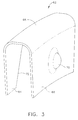
- FIGS 2 and 3 illustrate an exemplary balance weight 62 for use with the disks 24 and 42.
- the balance weight 62 is generally U-shaped in cross-section and includes spaced-apart front and rear walls 64 and 66 interconnected by an end wall 68.
- the balance weight 62 is made from a suitable alloy and may be formed by methods such as casting, stamping, or machining.
- the balance weight 62 is slightly resilient, such that the front and rear walls 64 and 66 can be compressed towards each other for installation but will spring back to their original shape.
- the rear wall 66 of the balance weight 62 includes a dimple 70 protruding outwardly therefrom.
- the front wall 64 includes a cutout 72 which is aligned with the lateral and radial position of the dimple 70, to allow the dimple 70 to be formed in the rear wall 66 using a forming die or other similar tooling.
- the cutout 72 may be eliminated.
- the overall dimensions, material thickness, and specific cross-sectional profile of the balance weight 62 may be varied in size to increase or decrease its mass as required for a particular application.
- FIG 4 illustrates how the balance weight 62 is installed. It will be understood that the installation process is identical for the first and second disks 24 and 42, and therefore will only be discussed with respect to disk 24.
- the balance weight 62 is positioned in the slot 52 by compressing the balance weight 62 such that it slides between the aft side 50 of the first stage disk 24 and the flange 46.
- the balance weight 62 is positioned such that the dimple 70 is aligned with one the apertures 54 in the flange 46. Once the dimple 70 is aligned with the aperture 54, the balance weight 62 is released to allow it to expand in the slot 52, forcing the dimple 70 into the aperture 54 and thereby securing the balance weight 62.
- the balance weight 62 will be retained by the dimple engagement and friction forces.
- the balance weight 62 is further secured within the slot 52 by rotational forces caused by the rotation of the first stage disk 24.
- FIGS 5-7 illustrate an alternative balance weight 162 which is similar in construction to the balance weight 162 and includes spaced-apart front and rear walls 164 and 166 interconnected by an end wall 168.
- the balance weight 162 is made from a suitable alloy and may be formed by methods such as casting, stamping, or machining.
- the balance weight 162 is slightly resilient, such that the front and rear walls 164 and 166 can be compressed towards each other for installation but will spring back to their original shape.
- the rear wall 166 includes a pin 170 protruding outwardly therefrom.
- the pin 170 may be a separate element which is attached to the rear wall 166 by brazing or welding, or it may be integrally formed with the rear wall 166.
- an aft face 172 of the pin 170 is angled or sloped radially outward to ease installation of the balance weight 162; however, it should be appreciated that the aft face 172 may also be flat or have any other suitable geometry.
- a lip 174 extends axially aft from a radially inner edge of the rear wall 166.
- the lip 174 may be sized according to the amount of mass needed for balancing, and may also provide additional stability when the balance weight 162 is installed.
- the overall dimensions, material thickness, and specific cross-sectional profile of the balance weight 162 may be varied in size to increase or decrease its mass as required for a particular application.
- FIG 8 illustrates how the balance weight 162 is installed.
- the balance weight 162 is positioned in the slot 52 by compressing it such that it slides between the aft side 50 of the first stage disk 24 and the flange 46.
- the balance weight 162 is positioned such that the pin 170 is aligned with one the apertures 54 in the flange 46. Once the pin 170 is aligned with the aperture 76, the balance weight 162 is released to allow it to expand in the slot 52, forcing the pin 170 into the aperture 54 and thereby securing the balance weight 162.
- the balance weight 162 will be retained by the pin engagement and friction forces.
- the balance weight 162 is further secured within the slot 52 by rotational forces caused by the rotation of the first stage disk 24.
Landscapes
- Engineering & Computer Science (AREA)
- Mechanical Engineering (AREA)
- General Engineering & Computer Science (AREA)
- Turbine Rotor Nozzle Sealing (AREA)
Applications Claiming Priority (1)
| Application Number | Priority Date | Filing Date | Title |
|---|---|---|---|
| US12/241,953 US8186954B2 (en) | 2008-09-30 | 2008-09-30 | Gas turbine engine rotor and balance weight therefor |
Publications (3)
| Publication Number | Publication Date |
|---|---|
| EP2169181A2 true EP2169181A2 (de) | 2010-03-31 |
| EP2169181A3 EP2169181A3 (de) | 2012-10-24 |
| EP2169181B1 EP2169181B1 (de) | 2013-11-06 |
Family
ID=41258939
Family Applications (1)
| Application Number | Title | Priority Date | Filing Date |
|---|---|---|---|
| EP09171326.3A Not-in-force EP2169181B1 (de) | 2008-09-30 | 2009-09-25 | Gasturbinenrotor und zugehöriges Auswuchtgewicht |
Country Status (4)
| Country | Link |
|---|---|
| US (1) | US8186954B2 (de) |
| EP (1) | EP2169181B1 (de) |
| JP (1) | JP5345490B2 (de) |
| CA (1) | CA2680645C (de) |
Cited By (4)
| Publication number | Priority date | Publication date | Assignee | Title |
|---|---|---|---|---|
| EP2397651A1 (de) * | 2010-06-17 | 2011-12-21 | Siemens Aktiengesellschaft | Gleichgewichtskorrekturgewicht mit konstanter Masse |
| EP2808486A1 (de) * | 2013-05-27 | 2014-12-03 | MTU Aero Engines GmbH | Wuchtkörper für eine Laufschaufelanordnung |
| EP3584406A1 (de) * | 2018-06-18 | 2019-12-25 | United Technologies Corporation | Klammer- und stiftausgleich für einen rotor |
| EP4036372A1 (de) * | 2021-02-02 | 2022-08-03 | Pratt & Whitney Canada Corp. | Rotorauswuchtanordnung |
Families Citing this family (23)
| Publication number | Priority date | Publication date | Assignee | Title |
|---|---|---|---|---|
| US9297258B2 (en) * | 2009-06-16 | 2016-03-29 | General Electric Company | Trapped spring balance weight and rotor assembly |
| US8668457B2 (en) | 2010-10-29 | 2014-03-11 | United Technologies Corporation | Gas turbine engine trim balance |
| US8974180B2 (en) | 2011-11-17 | 2015-03-10 | General Electric Company | System and method for estimating operating temperature of turbo machinery |
| EP2839114A1 (de) * | 2012-04-20 | 2015-02-25 | General Electric Company | Ausgleichsgewicht mit eingeschlossener feder und rotoranordnung |
| JP2013253522A (ja) * | 2012-06-06 | 2013-12-19 | Ihi Corp | ブリスク |
| US9388697B2 (en) * | 2012-07-17 | 2016-07-12 | Solar Turbines Incorporated | First stage compressor disk configured for balancing the compressor rotor assembly |
| US9957799B2 (en) | 2012-09-19 | 2018-05-01 | United Technologies Corporation | Balance ring for gas turbine engine |
| US10247003B2 (en) | 2013-09-26 | 2019-04-02 | United Technologies Corporation | Balanced rotating component for a gas powered engine |
| US10544678B2 (en) | 2015-02-04 | 2020-01-28 | United Technologies Corporation | Gas turbine engine rotor disk balancing |
| US10968744B2 (en) | 2017-05-04 | 2021-04-06 | Rolls-Royce Corporation | Turbine rotor assembly having a retaining collar for a bayonet mount |
| US10865646B2 (en) * | 2017-05-04 | 2020-12-15 | Rolls-Royce Corporation | Turbine assembly with auxiliary wheel |
| US10774678B2 (en) | 2017-05-04 | 2020-09-15 | Rolls-Royce Corporation | Turbine assembly with auxiliary wheel |
| DE102017109952A1 (de) * | 2017-05-09 | 2018-11-15 | Rolls-Royce Deutschland Ltd & Co Kg | Rotorvorrichtung einer Strömungsmaschine |
| US10697300B2 (en) * | 2017-12-14 | 2020-06-30 | Raytheon Technologies Corporation | Rotor balance weight system |
| FR3092134B1 (fr) * | 2019-01-30 | 2021-02-12 | Safran Aircraft Engines | turbine avec dispositif d’équilibrage amélioré |
| FR3102205B1 (fr) * | 2019-10-17 | 2022-08-12 | Safran Aircraft Engines | Rotor de turbomachine à masselotte |
| US11732585B2 (en) | 2021-01-28 | 2023-08-22 | General Electric Company | Trapped rotatable weights to improve rotor balance |
| CN113172412B (zh) * | 2021-05-06 | 2022-05-27 | 哈尔滨电机厂有限责任公司 | 一种水轮发电机动平衡配重块的安装方法 |
| KR20230091604A (ko) * | 2021-12-16 | 2023-06-23 | 한화에어로스페이스 주식회사 | 보호심을 구비하는 로터 어셈블리 및 이를 포함하는 가스 터빈 엔진 |
| US11976564B1 (en) | 2023-03-30 | 2024-05-07 | Rolls-Royce North American Technologies Inc. | Splined balance weight for rotating components in gas turbine engines |
| US12018579B1 (en) | 2023-08-08 | 2024-06-25 | Rolls-Royce North American Technologies Inc. | Clocking balance weight rotor assembly for gas turbine engines |
| US12305528B2 (en) | 2023-08-08 | 2025-05-20 | Rolls-Royce North American Technologies Inc. | Rotor assembly for gas turbine engines with replaceable balance weight bands |
| US12018580B1 (en) | 2023-08-08 | 2024-06-25 | Rolls-Royce North American Technologies Inc. | Rotor assembly for gas turbine engines with replaceable balance weight pins |
Family Cites Families (15)
| Publication number | Priority date | Publication date | Assignee | Title |
|---|---|---|---|---|
| US2639885A (en) * | 1950-03-23 | 1953-05-26 | United Aircraft Corp | Rotor construction for compressors and turbines |
| US3070351A (en) * | 1959-02-06 | 1962-12-25 | Gen Motors Corp | Blade retention |
| GB1081605A (en) * | 1963-11-13 | 1967-08-31 | M A N Turbo G M B H | Improvements in or relating to balance weights and their location on rotary bodies |
| US3304053A (en) * | 1965-04-12 | 1967-02-14 | United Aircraft Corp | Balancing weights for a multistage fluid motor |
| US3736811A (en) * | 1971-08-19 | 1973-06-05 | Gen Electric | Balance weight attachment for turbine wheels |
| US4477226A (en) * | 1983-05-09 | 1984-10-16 | General Electric Company | Balance for rotating member |
| US5018943A (en) * | 1989-04-17 | 1991-05-28 | General Electric Company | Boltless balance weight for turbine rotors |
| JPH0319401U (de) * | 1989-07-07 | 1991-02-26 | ||
| EP0437977A1 (de) * | 1990-01-18 | 1991-07-24 | United Technologies Corporation | Randkonfiguration einer Turbinenschiebe |
| US5205189A (en) * | 1990-12-17 | 1993-04-27 | General Electric Company | Engine shaft balance assembly |
| US6481969B2 (en) * | 1999-05-10 | 2002-11-19 | General Electric Company | Apparatus and methods for balancing turbine rotors |
| US6279420B1 (en) * | 1999-08-18 | 2001-08-28 | General Electric Co. | Balance weight for a rotary component in turbomachinery, methods of installation and installation tools |
| FR2868807B1 (fr) * | 2004-04-09 | 2008-12-05 | Snecma Moteurs Sa | Dispositif d'equilibrage d'une piece en rotation en particulier d'un rotor de turboreacteur |
| US7371042B2 (en) * | 2004-12-21 | 2008-05-13 | General Electric Company | Method and apparatus for balancing gas turbine engines |
| US7465146B2 (en) * | 2005-12-05 | 2008-12-16 | General Electric Company | Methods and systems for turbine rotor balancing |
-
2008
- 2008-09-30 US US12/241,953 patent/US8186954B2/en active Active
-
2009
- 2009-09-24 JP JP2009218351A patent/JP5345490B2/ja not_active Expired - Fee Related
- 2009-09-24 CA CA2680645A patent/CA2680645C/en not_active Expired - Fee Related
- 2009-09-25 EP EP09171326.3A patent/EP2169181B1/de not_active Not-in-force
Cited By (9)
| Publication number | Priority date | Publication date | Assignee | Title |
|---|---|---|---|---|
| EP2397651A1 (de) * | 2010-06-17 | 2011-12-21 | Siemens Aktiengesellschaft | Gleichgewichtskorrekturgewicht mit konstanter Masse |
| WO2011157547A1 (en) * | 2010-06-17 | 2011-12-22 | Siemens Aktiengesellschaft | Balance correction weight providing constant mass |
| US9260977B2 (en) | 2010-06-17 | 2016-02-16 | Siemens Aktiengesellschaft | Balance correction weight providing constant mass |
| EP2808486A1 (de) * | 2013-05-27 | 2014-12-03 | MTU Aero Engines GmbH | Wuchtkörper für eine Laufschaufelanordnung |
| US9816379B2 (en) | 2013-05-27 | 2017-11-14 | MTU Aero Engines AG | Balancing body for a continuous blade arrangement |
| EP3584406A1 (de) * | 2018-06-18 | 2019-12-25 | United Technologies Corporation | Klammer- und stiftausgleich für einen rotor |
| US10907477B2 (en) | 2018-06-18 | 2021-02-02 | Raytheon Technologies Corporation | Clip and pin balance for rotor |
| EP4036372A1 (de) * | 2021-02-02 | 2022-08-03 | Pratt & Whitney Canada Corp. | Rotorauswuchtanordnung |
| US11578599B2 (en) | 2021-02-02 | 2023-02-14 | Pratt & Whitney Canada Corp. | Rotor balance assembly |
Also Published As
| Publication number | Publication date |
|---|---|
| JP5345490B2 (ja) | 2013-11-20 |
| EP2169181A3 (de) | 2012-10-24 |
| EP2169181B1 (de) | 2013-11-06 |
| CA2680645A1 (en) | 2010-03-30 |
| JP2010084760A (ja) | 2010-04-15 |
| US20100080689A1 (en) | 2010-04-01 |
| CA2680645C (en) | 2013-08-13 |
| US8186954B2 (en) | 2012-05-29 |
Similar Documents
| Publication | Publication Date | Title |
|---|---|---|
| EP2169181B1 (de) | Gasturbinenrotor und zugehöriges Auswuchtgewicht | |
| EP3106614B1 (de) | Rotordämpfer | |
| US9033657B2 (en) | Gas turbine engine including lift-off finger seals, lift-off finger seals, and method for the manufacture thereof | |
| EP2540979A2 (de) | Rotoranordnung und umkehrbare Turbinenschaufelhaltevorrichtung dafür | |
| US9771802B2 (en) | Thermal shields for gas turbine rotor | |
| JP2000186507A (ja) | 軸流ガスタ―ビンエンジン | |
| JP2000186571A (ja) | 回転機械の組立方法およびガスタ―ビンエンジンの組立方法 | |
| EP3477047B1 (de) | Segmentierte strukturverbindungen zur scheibenfrequenzabstimmung und zugehöriges gasturbinentriebwerk mit solchen strukturverbindungen | |
| CN105229262A (zh) | 叶片系统和制造叶片系统的对应方法 | |
| EP3584406B1 (de) | Klammer- und stiftausgleich für einen rotor | |
| US7530791B2 (en) | Turbine blade retaining apparatus | |
| WO2017162365A1 (en) | Damping vibrations in a gas turbine | |
| US9957799B2 (en) | Balance ring for gas turbine engine | |
| US12612863B2 (en) | Test blade for gas turbine engine and method of making | |
| EP2977547A1 (de) | Rotorschaufelschwalbenschwanz mit abgerundeten laufflächen | |
| CA3232837A1 (en) | Test blade for gas turbine engine and method of making | |
| US11686202B1 (en) | Rotor damper with contact biasing feature for turbine engines | |
| US10024165B2 (en) | De-oiler balance weights for turbomachine rotors and systems for removing excess oil from turbomachine rotors | |
| CN114060099A (zh) | 用于燃气涡轮发动机的涡轮区段的转子组件 | |
| US12467366B2 (en) | Turbine engine with a nozzle having cooling features | |
| US12044135B1 (en) | Stator vane with variable center of gravity |
Legal Events
| Date | Code | Title | Description |
|---|---|---|---|
| PUAI | Public reference made under article 153(3) epc to a published international application that has entered the european phase |
Free format text: ORIGINAL CODE: 0009012 |
|
| AK | Designated contracting states |
Kind code of ref document: A2 Designated state(s): AT BE BG CH CY CZ DE DK EE ES FI FR GB GR HR HU IE IS IT LI LT LU LV MC MK MT NL NO PL PT RO SE SI SK SM TR |
|
| AX | Request for extension of the european patent |
Extension state: AL BA RS |
|
| PUAL | Search report despatched |
Free format text: ORIGINAL CODE: 0009013 |
|
| AK | Designated contracting states |
Kind code of ref document: A3 Designated state(s): AT BE BG CH CY CZ DE DK EE ES FI FR GB GR HR HU IE IS IT LI LT LU LV MC MK MT NL NO PL PT RO SE SI SK SM TR |
|
| AX | Request for extension of the european patent |
Extension state: AL BA RS |
|
| RIC1 | Information provided on ipc code assigned before grant |
Ipc: F01D 5/02 20060101AFI20120919BHEP |
|
| 17P | Request for examination filed |
Effective date: 20130424 |
|
| GRAP | Despatch of communication of intention to grant a patent |
Free format text: ORIGINAL CODE: EPIDOSNIGR1 |
|
| INTG | Intention to grant announced |
Effective date: 20130611 |
|
| GRAS | Grant fee paid |
Free format text: ORIGINAL CODE: EPIDOSNIGR3 |
|
| GRAA | (expected) grant |
Free format text: ORIGINAL CODE: 0009210 |
|
| AK | Designated contracting states |
Kind code of ref document: B1 Designated state(s): AT BE BG CH CY CZ DE DK EE ES FI FR GB GR HR HU IE IS IT LI LT LU LV MC MK MT NL NO PL PT RO SE SI SK SM TR |
|
| REG | Reference to a national code |
Ref country code: GB Ref legal event code: FG4D |
|
| REG | Reference to a national code |
Ref country code: CH Ref legal event code: EP |
|
| REG | Reference to a national code |
Ref country code: AT Ref legal event code: REF Ref document number: 639643 Country of ref document: AT Kind code of ref document: T Effective date: 20131215 |
|
| REG | Reference to a national code |
Ref country code: IE Ref legal event code: FG4D |
|
| REG | Reference to a national code |
Ref country code: DE Ref legal event code: R096 Ref document number: 602009019857 Country of ref document: DE Effective date: 20140102 |
|
| REG | Reference to a national code |
Ref country code: NL Ref legal event code: VDEP Effective date: 20131106 |
|
| REG | Reference to a national code |
Ref country code: AT Ref legal event code: MK05 Ref document number: 639643 Country of ref document: AT Kind code of ref document: T Effective date: 20131106 |
|
| REG | Reference to a national code |
Ref country code: LT Ref legal event code: MG4D |
|
| PG25 | Lapsed in a contracting state [announced via postgrant information from national office to epo] |
Ref country code: LT Free format text: LAPSE BECAUSE OF FAILURE TO SUBMIT A TRANSLATION OF THE DESCRIPTION OR TO PAY THE FEE WITHIN THE PRESCRIBED TIME-LIMIT Effective date: 20131106 Ref country code: HR Free format text: LAPSE BECAUSE OF FAILURE TO SUBMIT A TRANSLATION OF THE DESCRIPTION OR TO PAY THE FEE WITHIN THE PRESCRIBED TIME-LIMIT Effective date: 20131106 Ref country code: FI Free format text: LAPSE BECAUSE OF FAILURE TO SUBMIT A TRANSLATION OF THE DESCRIPTION OR TO PAY THE FEE WITHIN THE PRESCRIBED TIME-LIMIT Effective date: 20131106 Ref country code: SE Free format text: LAPSE BECAUSE OF FAILURE TO SUBMIT A TRANSLATION OF THE DESCRIPTION OR TO PAY THE FEE WITHIN THE PRESCRIBED TIME-LIMIT Effective date: 20131106 Ref country code: IS Free format text: LAPSE BECAUSE OF FAILURE TO SUBMIT A TRANSLATION OF THE DESCRIPTION OR TO PAY THE FEE WITHIN THE PRESCRIBED TIME-LIMIT Effective date: 20140306 Ref country code: NO Free format text: LAPSE BECAUSE OF FAILURE TO SUBMIT A TRANSLATION OF THE DESCRIPTION OR TO PAY THE FEE WITHIN THE PRESCRIBED TIME-LIMIT Effective date: 20140206 Ref country code: NL Free format text: LAPSE BECAUSE OF FAILURE TO SUBMIT A TRANSLATION OF THE DESCRIPTION OR TO PAY THE FEE WITHIN THE PRESCRIBED TIME-LIMIT Effective date: 20131106 |
|
| PG25 | Lapsed in a contracting state [announced via postgrant information from national office to epo] |
Ref country code: BE Free format text: LAPSE BECAUSE OF FAILURE TO SUBMIT A TRANSLATION OF THE DESCRIPTION OR TO PAY THE FEE WITHIN THE PRESCRIBED TIME-LIMIT Effective date: 20131106 Ref country code: LV Free format text: LAPSE BECAUSE OF FAILURE TO SUBMIT A TRANSLATION OF THE DESCRIPTION OR TO PAY THE FEE WITHIN THE PRESCRIBED TIME-LIMIT Effective date: 20131106 Ref country code: ES Free format text: LAPSE BECAUSE OF FAILURE TO SUBMIT A TRANSLATION OF THE DESCRIPTION OR TO PAY THE FEE WITHIN THE PRESCRIBED TIME-LIMIT Effective date: 20131106 Ref country code: AT Free format text: LAPSE BECAUSE OF FAILURE TO SUBMIT A TRANSLATION OF THE DESCRIPTION OR TO PAY THE FEE WITHIN THE PRESCRIBED TIME-LIMIT Effective date: 20131106 |
|
| PG25 | Lapsed in a contracting state [announced via postgrant information from national office to epo] |
Ref country code: PT Free format text: LAPSE BECAUSE OF FAILURE TO SUBMIT A TRANSLATION OF THE DESCRIPTION OR TO PAY THE FEE WITHIN THE PRESCRIBED TIME-LIMIT Effective date: 20140306 |
|
| PG25 | Lapsed in a contracting state [announced via postgrant information from national office to epo] |
Ref country code: EE Free format text: LAPSE BECAUSE OF FAILURE TO SUBMIT A TRANSLATION OF THE DESCRIPTION OR TO PAY THE FEE WITHIN THE PRESCRIBED TIME-LIMIT Effective date: 20131106 |
|
| REG | Reference to a national code |
Ref country code: DE Ref legal event code: R097 Ref document number: 602009019857 Country of ref document: DE |
|
| PG25 | Lapsed in a contracting state [announced via postgrant information from national office to epo] |
Ref country code: SK Free format text: LAPSE BECAUSE OF FAILURE TO SUBMIT A TRANSLATION OF THE DESCRIPTION OR TO PAY THE FEE WITHIN THE PRESCRIBED TIME-LIMIT Effective date: 20131106 Ref country code: PL Free format text: LAPSE BECAUSE OF FAILURE TO SUBMIT A TRANSLATION OF THE DESCRIPTION OR TO PAY THE FEE WITHIN THE PRESCRIBED TIME-LIMIT Effective date: 20131106 Ref country code: IT Free format text: LAPSE BECAUSE OF FAILURE TO SUBMIT A TRANSLATION OF THE DESCRIPTION OR TO PAY THE FEE WITHIN THE PRESCRIBED TIME-LIMIT Effective date: 20131106 Ref country code: CZ Free format text: LAPSE BECAUSE OF FAILURE TO SUBMIT A TRANSLATION OF THE DESCRIPTION OR TO PAY THE FEE WITHIN THE PRESCRIBED TIME-LIMIT Effective date: 20131106 Ref country code: RO Free format text: LAPSE BECAUSE OF FAILURE TO SUBMIT A TRANSLATION OF THE DESCRIPTION OR TO PAY THE FEE WITHIN THE PRESCRIBED TIME-LIMIT Effective date: 20131106 |
|
| PLBE | No opposition filed within time limit |
Free format text: ORIGINAL CODE: 0009261 |
|
| STAA | Information on the status of an ep patent application or granted ep patent |
Free format text: STATUS: NO OPPOSITION FILED WITHIN TIME LIMIT |
|
| PG25 | Lapsed in a contracting state [announced via postgrant information from national office to epo] |
Ref country code: DK Free format text: LAPSE BECAUSE OF FAILURE TO SUBMIT A TRANSLATION OF THE DESCRIPTION OR TO PAY THE FEE WITHIN THE PRESCRIBED TIME-LIMIT Effective date: 20131106 |
|
| 26N | No opposition filed |
Effective date: 20140807 |
|
| REG | Reference to a national code |
Ref country code: DE Ref legal event code: R097 Ref document number: 602009019857 Country of ref document: DE Effective date: 20140807 |
|
| PG25 | Lapsed in a contracting state [announced via postgrant information from national office to epo] |
Ref country code: SI Free format text: LAPSE BECAUSE OF FAILURE TO SUBMIT A TRANSLATION OF THE DESCRIPTION OR TO PAY THE FEE WITHIN THE PRESCRIBED TIME-LIMIT Effective date: 20131106 |
|
| PG25 | Lapsed in a contracting state [announced via postgrant information from national office to epo] |
Ref country code: MC Free format text: LAPSE BECAUSE OF FAILURE TO SUBMIT A TRANSLATION OF THE DESCRIPTION OR TO PAY THE FEE WITHIN THE PRESCRIBED TIME-LIMIT Effective date: 20131106 Ref country code: LU Free format text: LAPSE BECAUSE OF FAILURE TO SUBMIT A TRANSLATION OF THE DESCRIPTION OR TO PAY THE FEE WITHIN THE PRESCRIBED TIME-LIMIT Effective date: 20140925 |
|
| REG | Reference to a national code |
Ref country code: CH Ref legal event code: PL |
|
| REG | Reference to a national code |
Ref country code: IE Ref legal event code: MM4A |
|
| REG | Reference to a national code |
Ref country code: FR Ref legal event code: ST Effective date: 20150529 |
|
| PG25 | Lapsed in a contracting state [announced via postgrant information from national office to epo] |
Ref country code: CH Free format text: LAPSE BECAUSE OF NON-PAYMENT OF DUE FEES Effective date: 20140930 Ref country code: LI Free format text: LAPSE BECAUSE OF NON-PAYMENT OF DUE FEES Effective date: 20140930 |
|
| PG25 | Lapsed in a contracting state [announced via postgrant information from national office to epo] |
Ref country code: IE Free format text: LAPSE BECAUSE OF NON-PAYMENT OF DUE FEES Effective date: 20140925 Ref country code: FR Free format text: LAPSE BECAUSE OF NON-PAYMENT OF DUE FEES Effective date: 20140930 |
|
| PG25 | Lapsed in a contracting state [announced via postgrant information from national office to epo] |
Ref country code: SM Free format text: LAPSE BECAUSE OF FAILURE TO SUBMIT A TRANSLATION OF THE DESCRIPTION OR TO PAY THE FEE WITHIN THE PRESCRIBED TIME-LIMIT Effective date: 20131106 |
|
| PG25 | Lapsed in a contracting state [announced via postgrant information from national office to epo] |
Ref country code: GR Free format text: LAPSE BECAUSE OF FAILURE TO SUBMIT A TRANSLATION OF THE DESCRIPTION OR TO PAY THE FEE WITHIN THE PRESCRIBED TIME-LIMIT Effective date: 20140207 Ref country code: CY Free format text: LAPSE BECAUSE OF FAILURE TO SUBMIT A TRANSLATION OF THE DESCRIPTION OR TO PAY THE FEE WITHIN THE PRESCRIBED TIME-LIMIT Effective date: 20131106 Ref country code: MT Free format text: LAPSE BECAUSE OF FAILURE TO SUBMIT A TRANSLATION OF THE DESCRIPTION OR TO PAY THE FEE WITHIN THE PRESCRIBED TIME-LIMIT Effective date: 20131106 Ref country code: BG Free format text: LAPSE BECAUSE OF FAILURE TO SUBMIT A TRANSLATION OF THE DESCRIPTION OR TO PAY THE FEE WITHIN THE PRESCRIBED TIME-LIMIT Effective date: 20131106 |
|
| PG25 | Lapsed in a contracting state [announced via postgrant information from national office to epo] |
Ref country code: HU Free format text: LAPSE BECAUSE OF FAILURE TO SUBMIT A TRANSLATION OF THE DESCRIPTION OR TO PAY THE FEE WITHIN THE PRESCRIBED TIME-LIMIT; INVALID AB INITIO Effective date: 20090925 Ref country code: TR Free format text: LAPSE BECAUSE OF FAILURE TO SUBMIT A TRANSLATION OF THE DESCRIPTION OR TO PAY THE FEE WITHIN THE PRESCRIBED TIME-LIMIT Effective date: 20131106 |
|
| PGFP | Annual fee paid to national office [announced via postgrant information from national office to epo] |
Ref country code: GB Payment date: 20160927 Year of fee payment: 8 |
|
| PGFP | Annual fee paid to national office [announced via postgrant information from national office to epo] |
Ref country code: DE Payment date: 20170927 Year of fee payment: 9 |
|
| GBPC | Gb: european patent ceased through non-payment of renewal fee |
Effective date: 20170925 |
|
| PG25 | Lapsed in a contracting state [announced via postgrant information from national office to epo] |
Ref country code: MK Free format text: LAPSE BECAUSE OF FAILURE TO SUBMIT A TRANSLATION OF THE DESCRIPTION OR TO PAY THE FEE WITHIN THE PRESCRIBED TIME-LIMIT Effective date: 20131106 |
|
| PG25 | Lapsed in a contracting state [announced via postgrant information from national office to epo] |
Ref country code: GB Free format text: LAPSE BECAUSE OF NON-PAYMENT OF DUE FEES Effective date: 20170925 |
|
| REG | Reference to a national code |
Ref country code: DE Ref legal event code: R119 Ref document number: 602009019857 Country of ref document: DE |
|
| PG25 | Lapsed in a contracting state [announced via postgrant information from national office to epo] |
Ref country code: DE Free format text: LAPSE BECAUSE OF NON-PAYMENT OF DUE FEES Effective date: 20190402 |