EP2169331A2 - Unité de refroidissement solaire - Google Patents
Unité de refroidissement solaire Download PDFInfo
- Publication number
- EP2169331A2 EP2169331A2 EP08167978A EP08167978A EP2169331A2 EP 2169331 A2 EP2169331 A2 EP 2169331A2 EP 08167978 A EP08167978 A EP 08167978A EP 08167978 A EP08167978 A EP 08167978A EP 2169331 A2 EP2169331 A2 EP 2169331A2
- Authority
- EP
- European Patent Office
- Prior art keywords
- solar
- refrigeration unit
- heat
- collector
- fluid
- Prior art date
- Legal status (The legal status is an assumption and is not a legal conclusion. Google has not performed a legal analysis and makes no representation as to the accuracy of the status listed.)
- Withdrawn
Links
- 238000001816 cooling Methods 0.000 title claims abstract description 66
- 239000012530 fluid Substances 0.000 claims abstract description 80
- 238000010521 absorption reaction Methods 0.000 claims abstract description 27
- 238000010438 heat treatment Methods 0.000 claims abstract description 8
- 238000005057 refrigeration Methods 0.000 claims description 127
- 239000006096 absorbing agent Substances 0.000 claims description 36
- 239000011521 glass Substances 0.000 claims description 26
- 238000003860 storage Methods 0.000 claims description 22
- 238000012546 transfer Methods 0.000 claims description 20
- 238000001179 sorption measurement Methods 0.000 claims description 19
- XLYOFNOQVPJJNP-UHFFFAOYSA-N water Substances O XLYOFNOQVPJJNP-UHFFFAOYSA-N 0.000 claims description 13
- 230000005611 electricity Effects 0.000 claims description 11
- UFHFLCQGNIYNRP-UHFFFAOYSA-N Hydrogen Chemical compound [H][H] UFHFLCQGNIYNRP-UHFFFAOYSA-N 0.000 claims description 10
- 229910052739 hydrogen Inorganic materials 0.000 claims description 10
- 239000001257 hydrogen Substances 0.000 claims description 10
- 230000006835 compression Effects 0.000 claims description 9
- 238000007906 compression Methods 0.000 claims description 9
- 239000000126 substance Substances 0.000 claims description 6
- 239000000446 fuel Substances 0.000 claims description 5
- 230000001105 regulatory effect Effects 0.000 claims description 5
- 238000000034 method Methods 0.000 claims description 4
- 239000011490 mineral wool Substances 0.000 claims description 4
- QVGXLLKOCUKJST-UHFFFAOYSA-N atomic oxygen Chemical compound [O] QVGXLLKOCUKJST-UHFFFAOYSA-N 0.000 claims description 3
- 229910052760 oxygen Inorganic materials 0.000 claims description 3
- 239000001301 oxygen Substances 0.000 claims description 3
- 230000031700 light absorption Effects 0.000 claims description 2
- 230000008569 process Effects 0.000 claims description 2
- 230000005855 radiation Effects 0.000 abstract description 18
- 230000005540 biological transmission Effects 0.000 abstract description 2
- 239000010410 layer Substances 0.000 description 45
- 238000004519 manufacturing process Methods 0.000 description 16
- 238000010248 power generation Methods 0.000 description 12
- 239000000975 dye Substances 0.000 description 5
- 230000000694 effects Effects 0.000 description 5
- 238000009413 insulation Methods 0.000 description 5
- 239000000463 material Substances 0.000 description 5
- 238000009434 installation Methods 0.000 description 4
- 230000003595 spectral effect Effects 0.000 description 4
- 239000011248 coating agent Substances 0.000 description 3
- 238000000576 coating method Methods 0.000 description 3
- 238000012423 maintenance Methods 0.000 description 3
- 238000011084 recovery Methods 0.000 description 3
- 230000009467 reduction Effects 0.000 description 3
- RYGMFSIKBFXOCR-UHFFFAOYSA-N Copper Chemical compound [Cu] RYGMFSIKBFXOCR-UHFFFAOYSA-N 0.000 description 2
- XUIMIQQOPSSXEZ-UHFFFAOYSA-N Silicon Chemical compound [Si] XUIMIQQOPSSXEZ-UHFFFAOYSA-N 0.000 description 2
- XAGFODPZIPBFFR-UHFFFAOYSA-N aluminium Chemical compound [Al] XAGFODPZIPBFFR-UHFFFAOYSA-N 0.000 description 2
- 229910052782 aluminium Inorganic materials 0.000 description 2
- 230000008901 benefit Effects 0.000 description 2
- 229910052802 copper Inorganic materials 0.000 description 2
- 239000010949 copper Substances 0.000 description 2
- 238000013461 design Methods 0.000 description 2
- 238000005516 engineering process Methods 0.000 description 2
- 238000001704 evaporation Methods 0.000 description 2
- 230000008020 evaporation Effects 0.000 description 2
- 230000017525 heat dissipation Effects 0.000 description 2
- 238000005338 heat storage Methods 0.000 description 2
- 230000003287 optical effect Effects 0.000 description 2
- 238000013021 overheating Methods 0.000 description 2
- 238000011056 performance test Methods 0.000 description 2
- 229910052710 silicon Inorganic materials 0.000 description 2
- 239000010703 silicon Substances 0.000 description 2
- 238000001228 spectrum Methods 0.000 description 2
- 230000009182 swimming Effects 0.000 description 2
- 238000012360 testing method Methods 0.000 description 2
- 230000000712 assembly Effects 0.000 description 1
- 238000000429 assembly Methods 0.000 description 1
- 230000008859 change Effects 0.000 description 1
- 238000010276 construction Methods 0.000 description 1
- 239000000498 cooling water Substances 0.000 description 1
- 230000002950 deficient Effects 0.000 description 1
- 230000001419 dependent effect Effects 0.000 description 1
- 238000011161 development Methods 0.000 description 1
- 238000005265 energy consumption Methods 0.000 description 1
- 230000007613 environmental effect Effects 0.000 description 1
- 230000002349 favourable effect Effects 0.000 description 1
- 238000010304 firing Methods 0.000 description 1
- 239000002803 fossil fuel Substances 0.000 description 1
- 231100001261 hazardous Toxicity 0.000 description 1
- 230000020169 heat generation Effects 0.000 description 1
- 238000003780 insertion Methods 0.000 description 1
- 230000037431 insertion Effects 0.000 description 1
- 230000007774 longterm Effects 0.000 description 1
- 230000007257 malfunction Effects 0.000 description 1
- 238000007726 management method Methods 0.000 description 1
- 239000000203 mixture Substances 0.000 description 1
- 238000005457 optimization Methods 0.000 description 1
- 238000004806 packaging method and process Methods 0.000 description 1
- 238000005086 pumping Methods 0.000 description 1
- 239000003507 refrigerant Substances 0.000 description 1
- 230000008439 repair process Effects 0.000 description 1
- 239000002356 single layer Substances 0.000 description 1
- 238000005476 soldering Methods 0.000 description 1
- 239000002904 solvent Substances 0.000 description 1
- 230000001629 suppression Effects 0.000 description 1
- 239000012780 transparent material Substances 0.000 description 1
- 238000011179 visual inspection Methods 0.000 description 1
- 239000002918 waste heat Substances 0.000 description 1
- 238000003466 welding Methods 0.000 description 1
- 239000002023 wood Substances 0.000 description 1
Images


Classifications
-
- F—MECHANICAL ENGINEERING; LIGHTING; HEATING; WEAPONS; BLASTING
- F25—REFRIGERATION OR COOLING; COMBINED HEATING AND REFRIGERATION SYSTEMS; HEAT PUMP SYSTEMS; MANUFACTURE OR STORAGE OF ICE; LIQUEFACTION SOLIDIFICATION OF GASES
- F25B—REFRIGERATION MACHINES, PLANTS OR SYSTEMS; COMBINED HEATING AND REFRIGERATION SYSTEMS; HEAT PUMP SYSTEMS
- F25B27/00—Machines, plants or systems, using particular sources of energy
- F25B27/002—Machines, plants or systems, using particular sources of energy using solar energy
-
- F—MECHANICAL ENGINEERING; LIGHTING; HEATING; WEAPONS; BLASTING
- F24—HEATING; RANGES; VENTILATING
- F24D—DOMESTIC- OR SPACE-HEATING SYSTEMS, e.g. CENTRAL HEATING SYSTEMS; DOMESTIC HOT-WATER SUPPLY SYSTEMS; ELEMENTS OR COMPONENTS THEREFOR
- F24D11/00—Central heating systems using heat accumulated in storage masses
- F24D11/002—Central heating systems using heat accumulated in storage masses water heating system
- F24D11/003—Central heating systems using heat accumulated in storage masses water heating system combined with solar energy
-
- F—MECHANICAL ENGINEERING; LIGHTING; HEATING; WEAPONS; BLASTING
- F24—HEATING; RANGES; VENTILATING
- F24F—AIR-CONDITIONING; AIR-HUMIDIFICATION; VENTILATION; USE OF AIR CURRENTS FOR SCREENING
- F24F5/00—Air-conditioning systems or apparatus not covered by F24F1/00 or F24F3/00, e.g. using solar heat or combined with household units such as an oven or water heater
- F24F5/0007—Air-conditioning systems or apparatus not covered by F24F1/00 or F24F3/00, e.g. using solar heat or combined with household units such as an oven or water heater cooling apparatus specially adapted for use in air-conditioning
- F24F5/001—Compression cycle type
-
- F—MECHANICAL ENGINEERING; LIGHTING; HEATING; WEAPONS; BLASTING
- F24—HEATING; RANGES; VENTILATING
- F24F—AIR-CONDITIONING; AIR-HUMIDIFICATION; VENTILATION; USE OF AIR CURRENTS FOR SCREENING
- F24F5/00—Air-conditioning systems or apparatus not covered by F24F1/00 or F24F3/00, e.g. using solar heat or combined with household units such as an oven or water heater
- F24F5/0046—Air-conditioning systems or apparatus not covered by F24F1/00 or F24F3/00, e.g. using solar heat or combined with household units such as an oven or water heater using natural energy, e.g. solar energy, energy from the ground
-
- F—MECHANICAL ENGINEERING; LIGHTING; HEATING; WEAPONS; BLASTING
- F24—HEATING; RANGES; VENTILATING
- F24S—SOLAR HEAT COLLECTORS; SOLAR HEAT SYSTEMS
- F24S10/00—Solar heat collectors using working fluids
- F24S10/40—Solar heat collectors using working fluids in absorbing elements surrounded by transparent enclosures, e.g. evacuated solar collectors
- F24S10/45—Solar heat collectors using working fluids in absorbing elements surrounded by transparent enclosures, e.g. evacuated solar collectors the enclosure being cylindrical
-
- F—MECHANICAL ENGINEERING; LIGHTING; HEATING; WEAPONS; BLASTING
- F24—HEATING; RANGES; VENTILATING
- F24S—SOLAR HEAT COLLECTORS; SOLAR HEAT SYSTEMS
- F24S23/00—Arrangements for concentrating solar-rays for solar heat collectors
- F24S23/70—Arrangements for concentrating solar-rays for solar heat collectors with reflectors
- F24S23/71—Arrangements for concentrating solar-rays for solar heat collectors with reflectors with parabolic reflective surfaces
-
- H—ELECTRICITY
- H02—GENERATION; CONVERSION OR DISTRIBUTION OF ELECTRIC POWER
- H02S—GENERATION OF ELECTRIC POWER BY CONVERSION OF INFRARED RADIATION, VISIBLE LIGHT OR ULTRAVIOLET LIGHT, e.g. USING PHOTOVOLTAIC [PV] MODULES
- H02S40/00—Components or accessories in combination with PV modules, not provided for in groups H02S10/00 - H02S30/00
- H02S40/40—Thermal components
- H02S40/44—Means to utilise heat energy, e.g. hybrid systems producing warm water and electricity at the same time
-
- F—MECHANICAL ENGINEERING; LIGHTING; HEATING; WEAPONS; BLASTING
- F24—HEATING; RANGES; VENTILATING
- F24D—DOMESTIC- OR SPACE-HEATING SYSTEMS, e.g. CENTRAL HEATING SYSTEMS; DOMESTIC HOT-WATER SUPPLY SYSTEMS; ELEMENTS OR COMPONENTS THEREFOR
- F24D2200/00—Heat sources or energy sources
- F24D2200/16—Waste heat
- F24D2200/24—Refrigeration
-
- F—MECHANICAL ENGINEERING; LIGHTING; HEATING; WEAPONS; BLASTING
- F24—HEATING; RANGES; VENTILATING
- F24F—AIR-CONDITIONING; AIR-HUMIDIFICATION; VENTILATION; USE OF AIR CURRENTS FOR SCREENING
- F24F5/00—Air-conditioning systems or apparatus not covered by F24F1/00 or F24F3/00, e.g. using solar heat or combined with household units such as an oven or water heater
- F24F5/0046—Air-conditioning systems or apparatus not covered by F24F1/00 or F24F3/00, e.g. using solar heat or combined with household units such as an oven or water heater using natural energy, e.g. solar energy, energy from the ground
- F24F2005/0064—Air-conditioning systems or apparatus not covered by F24F1/00 or F24F3/00, e.g. using solar heat or combined with household units such as an oven or water heater using natural energy, e.g. solar energy, energy from the ground using solar energy
- F24F2005/0067—Air-conditioning systems or apparatus not covered by F24F1/00 or F24F3/00, e.g. using solar heat or combined with household units such as an oven or water heater using natural energy, e.g. solar energy, energy from the ground using solar energy with photovoltaic panels
-
- F—MECHANICAL ENGINEERING; LIGHTING; HEATING; WEAPONS; BLASTING
- F24—HEATING; RANGES; VENTILATING
- F24F—AIR-CONDITIONING; AIR-HUMIDIFICATION; VENTILATION; USE OF AIR CURRENTS FOR SCREENING
- F24F2221/00—Details or features not otherwise provided for
- F24F2221/54—Heating and cooling, simultaneously or alternatively
-
- Y—GENERAL TAGGING OF NEW TECHNOLOGICAL DEVELOPMENTS; GENERAL TAGGING OF CROSS-SECTIONAL TECHNOLOGIES SPANNING OVER SEVERAL SECTIONS OF THE IPC; TECHNICAL SUBJECTS COVERED BY FORMER USPC CROSS-REFERENCE ART COLLECTIONS [XRACs] AND DIGESTS
- Y02—TECHNOLOGIES OR APPLICATIONS FOR MITIGATION OR ADAPTATION AGAINST CLIMATE CHANGE
- Y02B—CLIMATE CHANGE MITIGATION TECHNOLOGIES RELATED TO BUILDINGS, e.g. HOUSING, HOUSE APPLIANCES OR RELATED END-USER APPLICATIONS
- Y02B10/00—Integration of renewable energy sources in buildings
- Y02B10/20—Solar thermal
-
- Y—GENERAL TAGGING OF NEW TECHNOLOGICAL DEVELOPMENTS; GENERAL TAGGING OF CROSS-SECTIONAL TECHNOLOGIES SPANNING OVER SEVERAL SECTIONS OF THE IPC; TECHNICAL SUBJECTS COVERED BY FORMER USPC CROSS-REFERENCE ART COLLECTIONS [XRACs] AND DIGESTS
- Y02—TECHNOLOGIES OR APPLICATIONS FOR MITIGATION OR ADAPTATION AGAINST CLIMATE CHANGE
- Y02B—CLIMATE CHANGE MITIGATION TECHNOLOGIES RELATED TO BUILDINGS, e.g. HOUSING, HOUSE APPLIANCES OR RELATED END-USER APPLICATIONS
- Y02B30/00—Energy efficient heating, ventilation or air conditioning [HVAC]
- Y02B30/52—Heat recovery pumps, i.e. heat pump based systems or units able to transfer the thermal energy from one area of the premises or part of the facilities to a different one, improving the overall efficiency
-
- Y—GENERAL TAGGING OF NEW TECHNOLOGICAL DEVELOPMENTS; GENERAL TAGGING OF CROSS-SECTIONAL TECHNOLOGIES SPANNING OVER SEVERAL SECTIONS OF THE IPC; TECHNICAL SUBJECTS COVERED BY FORMER USPC CROSS-REFERENCE ART COLLECTIONS [XRACs] AND DIGESTS
- Y02—TECHNOLOGIES OR APPLICATIONS FOR MITIGATION OR ADAPTATION AGAINST CLIMATE CHANGE
- Y02E—REDUCTION OF GREENHOUSE GAS [GHG] EMISSIONS, RELATED TO ENERGY GENERATION, TRANSMISSION OR DISTRIBUTION
- Y02E10/00—Energy generation through renewable energy sources
- Y02E10/40—Solar thermal energy, e.g. solar towers
- Y02E10/44—Heat exchange systems
-
- Y—GENERAL TAGGING OF NEW TECHNOLOGICAL DEVELOPMENTS; GENERAL TAGGING OF CROSS-SECTIONAL TECHNOLOGIES SPANNING OVER SEVERAL SECTIONS OF THE IPC; TECHNICAL SUBJECTS COVERED BY FORMER USPC CROSS-REFERENCE ART COLLECTIONS [XRACs] AND DIGESTS
- Y02—TECHNOLOGIES OR APPLICATIONS FOR MITIGATION OR ADAPTATION AGAINST CLIMATE CHANGE
- Y02E—REDUCTION OF GREENHOUSE GAS [GHG] EMISSIONS, RELATED TO ENERGY GENERATION, TRANSMISSION OR DISTRIBUTION
- Y02E10/00—Energy generation through renewable energy sources
- Y02E10/50—Photovoltaic [PV] energy
-
- Y—GENERAL TAGGING OF NEW TECHNOLOGICAL DEVELOPMENTS; GENERAL TAGGING OF CROSS-SECTIONAL TECHNOLOGIES SPANNING OVER SEVERAL SECTIONS OF THE IPC; TECHNICAL SUBJECTS COVERED BY FORMER USPC CROSS-REFERENCE ART COLLECTIONS [XRACs] AND DIGESTS
- Y02—TECHNOLOGIES OR APPLICATIONS FOR MITIGATION OR ADAPTATION AGAINST CLIMATE CHANGE
- Y02E—REDUCTION OF GREENHOUSE GAS [GHG] EMISSIONS, RELATED TO ENERGY GENERATION, TRANSMISSION OR DISTRIBUTION
- Y02E10/00—Energy generation through renewable energy sources
- Y02E10/60—Thermal-PV hybrids
Definitions
- the present invention relates to a solar-powered collective collector for the simultaneous generation of electric power and thermal heat and a solar cooling unit and a method for the simultaneous provision of heat, cold and electricity by means of a solar cooling unit.
- Collective collectors which are designed in addition to the generation of electrical energy by the photovoltaic effect in photovoltaic cells at the same time to use the solar energy to generate heat in a suitably designed heat exchanger (solar thermal device) has been increasingly developed technically in recent years.
- Collective collectors are characterized in particular by their property to improve the overall efficiency of a collector provided with photovoltaic cells by receiving a suitably designed solar thermal device and thus increase the overall economy of the collector.
- a collector for the recovery of energy from the radiation of the sun known, which consists of a medium flowing through a heat exchanger and in addition of a photovoltaic collector.
- the thermal collectors are made from a visible and UV-transparent material, such that the infrared spectral range is the only absorbed region of the electromagnetic spectrum of sunlight.
- the choice of visible and UV light transmissive material allows these two spectral ranges to be used for the production of electrical energy by means of the photovoltaic part of the collector, which is connected downstream of the thermal collector with respect to the direction of incidence of the sunlight.
- the technical task of proposing a collective collector which on the one hand easy handling and an optimized thermal Has efficiency to supply plants with a high heat demand.
- a collective collector for the simultaneous generation of electric current and thermal heat which comprises the following components: a light entry disc, which is irradiated in an operating state of sunlight and limits the collective collector in an operating state at least to a sun facing side; at least one photovoltaic cell arranged in a first area; at least one light absorber layer disposed in a second surface; at least one pipeline filled with a fluid; wherein, in an operating state of the collector, the first surface faces a sun facing side, the first and second surfaces are disposed in full contact with each other, and the at least one photovoltaic cell allows passage of sunlight irradiated by the light entry plate in the direction of incidence onto the second surface, and wherein the second surface is in thermal contact with the at least one conduit, such that upon absorption-induced heating of the light absorber layer, the fluid in the conduit undergoes heat transfer.
- thermo energy production is clearly in the foreground , wherein a non-optimized, with respect to the possible efficiency significantly worse electrical energy production is accepted.
- present teaching contradicts the principle of increasing the efficiency of electric power generation by optimizing the operating conditions for electric power generation, as known for most of the prior art collectors.
- the present collective collector is designed so as to ensure the highest possible yield of thermal energy in a certain temperature range of up to about 100 ° C, in particular from 70 ° C to 95 ° C, at the same time even in economic terms electrical energy by means of covered photovoltaic cells is generated.
- the collective collector according to the invention is characterized by a very simple and extremely easy to maintain Structure, which is designed in particular for the operation of systems with a large heat demand.
- the collective collector proposed in the present case reduces the design effort extremely clearly by virtue of the fact that the at least one photovoltaic cell used for generating electrical energy is applied directly to the light absorber layer encompassed by the solar thermal device. Although the direct contact between the two components causes a significant reduction in the ability of the photovoltaic cell to generate electricity, but increases the yield of thermal energy, which is in the foreground in the present collective collector.
- the collective collector is particularly suitable for use in connection with refrigerators, which require the thermal generation of cold (negative heat) of a high Zutrags to heat energy.
- chillers also require electrical energy, which is necessary for the operation of fluidic pumping, setting and control elements. Consequently, chillers, as known in the art, are always limited to local operation in the vicinity of access to an electrical supply network. This, however, allows the operation only at a relatively small number of locations that can provide a secure electrical energy supply. In particular, this excludes all places in developing countries that can not secure a regulated energy supply.
- a solar refrigeration unit which comprises at least the following components: at least one solar collector system which has at least one photovoltaic cell and simultaneous generation of heat a solar thermal device for generating electric power, in particular at least one collective collector according to the previous Description provides; at least one refrigerating machine, which is designed as an adsorption and / or absorption chiller, and which is in fluidic contact with the solar thermal device via a fluid line system; an electrical control unit for the electrical and / or fluidic control of regulated components of the solar cooling unit; wherein the electrical energy for operation of the control unit and the refrigerating machine is provided either in direct or indirect form by the at least one photovoltaic cell, and the solar refrigeration unit is thus self-sufficient from an external power supply.
- a solar refrigeration unit which comprises at least one solar collector system which has at least one photovoltaic cell and simultaneous generation of heat a solar thermal device for generating electricity, in particular at least one collective collector according to the previously described type; at least one refrigerating machine, which is designed as an adsorption and / or absorption chiller, and which is in fluidic contact with the solar thermal device via a fluid line system; an electrical control unit for the electrical and / or fluidic control of regulated components of the solar cooling unit; wherein the solar refrigeration unit further comprises at least one transportable arrangement device, which is designed as a container or ship container, and in which the components of the solar refrigeration unit, which need not be exposed to the operation of sunlight, are arranged.
- a method for the simultaneous provision of heat, cold and electricity by means of a solar refrigeration unit comprising the following steps: simultaneous generation of heat and electricity by means of at least one solar collector system, which Generation of electric current at least one photovoltaic cell provides and which for generating heat, a solar thermal device provides, in particular by means of at least one collective collector according to the previously described type; Generating refrigeration by means of a refrigerating machine which is designed as an adsorption and / or absorption refrigerating machine and which is in fluidic contact with the solar thermal device of the solar collector system via a fluid line system; wherein the electrical energy for operation of the refrigerator is provided either in direct or indirect form by the at least one photovoltaic cell of the at least one solar collector system, and thus the solar refrigeration unit is autonomous from an external power supply.
- the solar refrigeration units described above require both an inflow of heat and electrical energy, both of which can be generated only solar technology.
- electrical and thermal energy can be generated by means of a collective collector of the type described above.
- the operation of the solar cooling unit according to the invention can be independent of access to an external electrical power supply. Consequently, the solar refrigeration unit can also be used in areas that have not yet been developed energy or not sufficiently developed.
- the proposed solar refrigeration units allow a completely CO 2 -neutral generation of cold, heat and electricity simultaneously.
- the collective collector for the simultaneous generation of electrical current and thermal heat, it is provided that the collective collector on at least one side facing away from the sun in an operating state, in particular also on sides which laterally delimit the at least one photovoltaic cell and the light absorber layer in an operating state or more layers of insulating, preferably one or more layers of mineral wool has.
- the collective collector is effectively protected from radiation of heat radiation to the outside and thus from an undesired loss of energy. According to the execution of the efficiency of the thermal heat production of the collective collector is increased.
- the additional insulation by providing at least one layer of insulating means, further reduces the efficiency of the photovoltaic cells for electrical power generation, this reduction can be partially offset by the fluid contained in the at least one pipeline rapidly enough accelerating the heat generated in the solar thermal device adequately Dissipates exchange flow. This dissipation of heat to a sufficient extent is ensured, especially when using the collective collector in conjunction with the proposed solar cooling unit, since the refrigeration machine included in the solar refrigeration unit requires a high amount of heat, and thus also a high removal of heat from the fluid line system, in which the fluid, which is in fluidic contact with the solar thermal device, is ensured.
- overheating of the photovoltaic cells can be prevented, for example, even when the solar cooling unit is operated in conjunction with the collective collector in summer conditions, since at high ambient temperatures not only the solar irradiation power but also the cooling power requested by a user are increased by the solar cooling unit.
- the increasingly demanded cooling capacity can only be covered by an increased demand for heat transfer from the collective collector.
- the heating of the photovoltaic cells in the collective collector can therefore be limited to about 100 ° Celsius and is therefore at about comparable operating temperatures in conventional photovoltaic modules, which do not provide any special heat adjustment.
- the energy yield of the solar radiation per area (solar overall efficiency of the collective collector) which can consequently be achieved with the collective collector is significantly increased in connection with the use of the above-described solar refrigeration unit over the extent of the prior art collective collectors.
- the light entry window is comprised of a glass tube in which the at least one photovoltaic cell, the at least one light absorption layer and the at least one pipeline filled with a fluid are arranged. Due to the geometric prerequisites, the operating temperatures in the operating state of such glass tube collective collectors are far above the operating temperatures of comparable collectors with flat geometry. Consequently, the use of glass tube collective collectors according to the invention only seems to make sense if sufficient heat dissipation can be ensured by the fluid contained in the at least one pipeline. This is the case when using the collective collector in conjunction with the previously described solar refrigeration unit. Due to the glass tube geometry of the collective collector is also modular buildable, with maintenance and repair only individual glass tube modules have to be maintained or replaced in order to restore the operating state of an approximately temporarily defective system.
- At least a predetermined inner portion of the glass tube is evacuated.
- the first and second surfaces are shown in a cross section perpendicular to the longitudinal extent of the glass tube as closed, in particular ellipsoidal curves, wherein the cross section is arranged at least one filled with a fluid pipe within the two closed curves.
- the collective collector further comprises at least one reflection element, in particular at least one parabolic reflection element, which effects a bundling of sunlight striking the at least one photovoltaic cell and / or at least one light absorber layer. Accordingly, according to the embodiment, the efficiency, in particular the thermal efficiency of the collective collector, can be further increased by also sunlight, which would otherwise be lost for use by the collective collector, this is again supplied by appropriate reflection.
- the solar refrigeration unit has at least one transportable arrangement device, which is designed in particular as a container or shipping container, for the arrangement of components of the solar refrigeration unit, which need not be exposed to sunlight for operation.
- the arrangement of the components in a container or shipping container can already be done at the factory.
- the containers may include all required for operation components and assemblies of the solar cooling unit before delivery from the factory. After the factory production or assembly of containers or shipping containers they must be transported only to their destinations in order to be taken there without further commission. On-site commissioning can therefore be based on a simple visual inspection of transport damage, limiting a connection of the necessary supply and discharge lines, filling of fluid-containing components and switching on the system.
- Typical solar refrigeration units arranged in containers or shipping containers have a total power output of about 10 kW to about 200 kW.
- an embodiment solar refrigeration unit can also be modular in individual modules.
- individual arrangement devices can be provided as modules which, in the case of a permanent installation of the solar refrigeration unit, for example in a building, merely have to be interconnected and connected to one another.
- the locating devices may be approximately stable shaped base frames formed in a predetermined manner on which individual components of the solar refrigeration unit are mounted.
- the individual modules In order to take a solar cooling unit into operation, the individual modules must be set up only in relation to each other, secured together and interconnected. For this purpose, quick connector systems for pipe connections can be used.
- the fluid line system comprises suitable fitting pieces with flanges and / or quick connector pieces, which allow to build up the fluid line system quickly and without errors after installation of the solar cooling unit.
- the electrical connection cable of the solar cooling unit can encoded plug with appropriate sockets include that allow for commissioning to make the wiring of all components confusion.
- the pre-arrangement of individual components of the solar refrigeration unit using the at least one transportable arrangement device can in this case be such that no specialist personnel and / or only a small amount of tools and no special tools are needed to set up the solar refrigeration unit at the destination. In particular, neither welding nor soldering are required.
- the solar refrigeration unit can also be distinguished by the fact that the at least one transportable arrangement device comprises mechanical means for transport facilitation, which are designed as material recesses, transport straps and / or crane eyes. This ensures easy and safe handling of the arrangement device, in particular during transport by forklift trucks and ships.
- a modular design of the solar refrigeration unit by means of the use of portable arrangement devices also facilitates the test of an entire solar refrigeration unit prior to delivery.
- the solar cooling unit is taken in a predetermined arrangement at the place of manufacture in operation and subjected to stress and performance tests. If the functionality of the system is secured, the system as a whole or individual modules can be packed and delivered immediately. A functionally hazardous insertion of individual components when setting up the solar refrigeration unit at the destination can therefore be omitted, since only modular components of the solar refrigeration unit must be related to each other or no structure is required.
- the arrangement of the solar refrigeration unit or its components in a transportable arrangement device also facilitates the assurance of the quality of the system, since it is subjected to just before packaging and delivery in the factory corresponding function and performance tests.
- the achieved performance values can be documented in a suitable manner, whereby a decrease of the total plant, for example by technical examiners, already can take place ex factory. Accordingly, the entire installation may be subject to a certification test system by an independent expert, without having to subsequently do so after installation at the place of destination.
- the solar cooling unit has an electrical interface to an external power grid to feed the generated by the at least one solar collector system and not required by the solar cooling unit amount of electrical energy in the external power grid.
- the latter has a storage device as a further component in order to store the amount of electrical energy in electrical or chemical form generated by the at least one solar collector system and not required by the solar refrigeration unit, so that it is too a later time in electrical form the solar cooling unit can be made available again.
- the execution can be dispensed with when generating an excess of electrical energy to the feed into an external power grid to use this excess, but the energy surplus of the solar cooling unit can be fed back when needed.
- the solar cooling unit can continue to be operated, even if the lighting conditions for generating electrical energy using the solar collector system are no longer sufficient.
- the operation of the solar refrigeration unit in cloudy conditions can be maintained even if due to the reduced light radiation not enough electrical energy can be produced by the solar collector system or the collective collector.
- a continuous operation of the solar cooling unit can also be ensured even in case of power outages or technical problems in the external power supply.
- the temperatures occurring at lower solar radiation in the at least one solar collector system or the at least one collective collector also cause a more efficient heat transfer to the fluid of the solar thermal device and a more efficient power generation by means of at least one photovoltaic cell.
- the storage device comprises at least one battery element. Consequently, the storage of the excess electrical energy, which is not required by the solar refrigeration unit, take place in electrical form, which can be withdrawn as needed immediately again as such the storage device.
- the storage device comprises a splitting device for splitting water into hydrogen and oxygen, and at least one storage container for storing hydrogen and a fuel cell for generating electricity by means of the stored in the storage container hydrogen.
- the amount of electrical energy not required by the solar refrigeration unit is stored in chemical form, which in the present case is distinguished by its environmental friendliness.
- a Fuel cell used which can alternatively be supplied in a suitable manner by not produced by the solar cooling unit hydrogen. Consequently, it can be ensured that the solar cooling unit can be supplied with sufficient electrical energy in insufficient light conditions, that is, in low sunlight or even at night.
- the chiller is designed such that it receives a heated in the at least one solar collector system or collector to a first temperature fluid via the fluid conduit system as input fluid for operation, and as the starting fluid, the fluid or another fluid a second compared to the first temperature lower temperature outputs, wherein in particular the first temperature between 50 ° C and 150 ° C, and in particular between 70 ° C and 95 ° C and the second temperature between 20 ° C and 50 ° C, in particular between 40 ° C and 45 ° C.
- the collective collectors described above are particularly suitable for supplying the cooling machine with heated input fluid, since the thermal efficiency of collective collectors for a yield in the temperature range up to about 100 ° C is particularly high.
- the output as a fluid fluid of the refrigerator fluid of a second temperature can be used in particular suitable for swimming pool heating or hot water.
- the solar refrigeration unit further comprises a high-temperature heat pump or an adsorption / absorption heat pump, which receives heat emitted from the chiller as heat transfer for operation and at least partially provided with by the at least one solar collector system or the collective collector electrical energy or is supplied with external energy to provide a heat output, which has a greater heat content than the heat transfer of the chiller emitted.
- a high temperature heat pump or adsorption / absorption heat pump thus allows the heat given off by the chiller, which is typically contained in a flow of fluid at a temperature of up to about 45 ° C, to increase, so that discharge a fluid with a temperature of up to 100 ° C can be achieved.
- This calorific treatment in particular allows industrial processes with sufficient heat or with a fluid flow to supply a sufficient temperature.
- industrial processes especially fluid flows with a temperature of 60 ° C to 100 ° C are in demand.
- the hot water of 60 ° C needed in a hotel can be manufactured with a relatively low efficiency because of the relatively small temperature difference of the water discharged from the refrigerator and the water discharged from the high temperature heat pump or the adsorption / absorption heat pump caloric particularly favorable transfer to heat allowed.
- a COP ratio of applied electric power to usable heat
- chiller as a heat source is that even without direct use of the heat, a suitable re-cooling of the solar cooling unit or the chiller is done, making no separate energy-intensive recooling is required.
- efficiency of the chiller can be additionally increased.
- the solar cooling unit is characterized in another embodiment in that it has a combined electrical and thermal power output between 1 kW and 1000 kW, in particular between 5 kW and 500 kW and preferably between 10 kW and 200 kW. Accordingly, the execution of solar cooling units are suitable for simultaneous cooling, heat and power supply of entire residential units, hotels, or small businesses.
- the solar refrigeration unit further comprises a compression refrigeration machine, which is provided in particular for operation by means of the energy provided by the at least one solar collector system in direct or indirect form.
- a compression refrigeration machine which is provided in particular for operation by means of the energy provided by the at least one solar collector system in direct or indirect form.
- the solar cooling unit can also provide cold available when the chiller is not available, for example, due to failure.
- the solar cooling unit according to the execution can continue to maintain refrigeration even during insufficient light conditions during the day or during the night hours by supplying a working according to the heat pump principle compression refrigeration machine with electrical energy, for example from their own storage facility or an external power grid.
- the electrical control unit controls the refrigeration machine such that it is only used with sufficient irradiation of sunlight on the solar collector system or the collective collector for producing a sufficient amount of thermal heat and this also for cold production. According to the execution of economic refrigeration can therefore always be given priority.
- the priority generation of cold can always be ensured.
- the operating time of the solar refrigeration unit can be extended and its operating conditions can be optimized by intelligent storage management by the electrical control unit. To improve efficiency, the control can also take into account the current outside temperature as a parameter and the expected future cooling capacity.
- the electrical control unit can be operated via at least one interface via an external network, in particular via the Internet.
- a suitable software which communicates with the electrical control unit, may also allow to transmit all necessary to control the solar cooling unit operating commands to the electrical control unit.
- all operating parameters recorded by sensors can be interrogated and manipulated by a remote operator. Such parameters include in particular temperature and flow values.
- each operating state of the solar refrigeration unit can be tracked in time, which malfunctions and failures can be more easily detected and eliminated by the user without costly maintenance.
- operational optimizations can be made by appropriate adjustments of the components of the solar cooling unit from a distance.
- An alternative to the network-controlled control unit is a satellite-based control unit.
- Fig. 1 shows a side sectional view through a first embodiment of the collector according to the invention 10, which faces the sun with a flat light entry window 13.
- the collective collector 10 is delimited laterally by the two limiting elements 18, which are shaped in such a way that they support or receive the light entry disk 13 appropriately.
- a further limiting element 18 is typically provided at the end.
- the collective collector 10 comprises at least one photovoltaic cell 11, which likewise faces the sun for receiving sunlight shining through the light entry window 13, and is arranged substantially parallel to the light entry window 13.
- the at least one photovoltaic cell 11 is arranged on a plane light absorber layer 14, which in turn is in contact with a plurality of pipelines 15, in the present case with a total of six illustrated pipelines 15.
- the area of the at least one photovoltaic cell and the area of the light absorber layer respectively define a first area F1 and a second area F2.
- At least one layer of insulating means 90 is arranged in the interior of the collective collector 10, which are arranged on the side facing away from the sun, or at least one photovoltaic cell 11 and the solar thermal device 12 laterally limit.
- the pipelines may also be included in the at least one layer of insulating means 90.
- the light entry plate 13 which is made of solar glass of a suitable thickness, for example, made of solar glass of 4 mm thickness, allowed in sunlight conditions, the passage of solar radiation without significantly absorb the light spectrum in the relevant for the production of electrical energy or heat energy spectral ranges .
- the sunlight radiates through an air space 19, which in an alternative embodiment of the present collective collector 10 can also be at least partially evacuated.
- the light entry window 13 furthermore ensures a suppression of heat losses by convection or by the emission of heat radiation.
- the at least one photovoltaic cell 11 is mounted directly below the glass cover.
- the sunlight strikes the at least one photovoltaic cell 11, in which above all the visible and the UV sunlight generates electrical current via the photovoltaic effect. Due to its optical properties, the at least one photovoltaic cell permits the passage of less suitable solar radiation for the generation of electrical power, which subsequently impinge on the light absorber layer 14.
- the optical behavior of the photovoltaic cell 11 can be ensured here by the layer thickness and by a suitable selection of the composition.
- a photovoltaic cell based on silicon technology is used for the at least one photovoltaic cell.
- the at least one photovoltaic cell 11 is applied to the light absorber layer 14.
- a small spacing of the two layers, shown in the drawing, serves merely to better illustrate this and is not present in a real embodiment.
- the sunlight radiating through the photovoltaic cell 11 is at least partially converted to heat on the light absorber layer 14 of the solar thermal device 12, which is further transmitted to the pipelines 15 via direct or indirect heat conduction.
- the light absorber layer 14 is made of copper or aluminum to maximize the heat output.
- the pipelines 15, which are in direct contact with the light absorber layer 14, are characterized by particularly thin-walled tube walls for suitable heat transfer to a fluid contained in the pipelines 15 (not designated here).
- Harp pipes which have a very small cross-section compared to the overall size of the collective collector 10, in particular a cross section of 6 mm, are particularly suitable. While maintaining a Exchange flow of the fluid contained in the pipes 15, the heat generated in the light absorber layer 14 can be dissipated in a suitable manner, whereby a cooling of the light absorber layer and thus the photovoltaic cell 11 is achieved.
- the insulating means 90 used to avoid excessive heat losses are designed as insulating suitable for thermal insulation, especially as layers of mineral wool, which is characterized by its good thermal insulation properties. Typical thicknesses of these layers of mineral wool are, for example, 60 mm on the side facing away from the sun.
- the layers of insulating 90 may be connected to the limiting elements 18, which may be designed as wood or aluminum components.
- a sufficient dissipation of heat from the collective collector 10 is ensured. Since at high temperatures usually a high cooling capacity is required by the solar cooling unit, a system of collective collector 10 and solar cooling unit always adapts to the ambient conditions and prevents heating of the at least one photovoltaic cell 11 to temperatures that an economic power generation not allow more. In particular, a heating is limited to about 100 ° C.
- Fig. 2 shows a further embodiment of the collective collector 10 according to the invention in a lateral sectional view.
- the collective collector 10 according to the invention again comprises at least one photovoltaic cell 11, which is in direct contact with a light absorber layer 14 of a solar thermal device 12.
- the light absorber layer 14 in turn is in direct contact with a conduit 15 which comprises a heat exchange fluid (not further described herein).
- a heat exchange fluid (not further described herein).
- the heat removal from the collective collector takes place according to the heat pipe principle.
- FIG Fig. 2 illustrated collective collector 10 bounded by a glass tube to the outside.
- the present glass tube 16 is evacuated.
- the glass tube 16 thus also includes a light entry plate 13 through which sunlight is blasted into the collective collector for heat recovery and power generation.
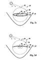
- Fig. 3a shows a further embodiment of the collective collector 10 according to the invention in a lateral sectional view.
- the illustrated collective collector 10 corresponds to the in Fig. 2 illustrated embodiment, but is extended to an external reflection element 17.
- the reflection element 17 is presently designed as a parabolic mirror, which allows not directly to the collective collector 10 impinging solar radiation or radiated by this re-emitted unused radiation for the recovery of electrical energy such as thermal energy back to the collective collector 10.
- the orientation of the reflection element 17 can be set in such a way that the radiation is concentrated onto the collective collector 10.
- Fig. 3b shows a side sectional view of another embodiment of the collector according to the invention 10, wherein compared to the in Fig. 3a illustrated embodiment, the at least one photovoltaic cell 11 together with the light absorber layer 14 are not shown as single-layer surfaces or layers, but as a closed in cross-section, possibly ellipsoidal, curve.
- the at least one photovoltaic cell 11 is shown as a photovoltaic cell coating on the light absorber layer 14, such a layer has manufacturing advantages.
- the present embodiment allows greater use of solar energy, since the reflected back to the glass tube 16 by the reflection element 17 sunlight on the side facing away from the sun of the collective collector 10 for generating electrical power and thermal heat is advantageously used. Consequently, the collective collector 10 which can be operated according to the heat pipe principle is in FIG Fig. 3b by one compared to the collective collector 10 in Fig. 3a higher efficiency.
- Fig. 3c shows a further embodiment of the collective collector 10 according to the invention in a lateral sectional view.
- the collective collector 10 shown comprises two parallel pipelines 15 which comprise a fluid (not shown) for heat exchange.
- a fluid not shown
- the fluid in the two pipes 15 comparatively larger amount of thermal energy removed from the system of the collective collector 10 and on the other hand due to the higher cooling capacity through the two pipes 15, a higher yield of electrical energy by in the at least one Photovoltaic cell 11 takes place taking place photovoltaic effect.
- Fig. 3d shows a side sectional view through a further embodiment of the collector according to the invention 10.
- the collective collector 10 shown largely corresponds to the in Fig. 3a illustrated collective collector 10, which is now provided with two pipes 15 instead of only one pipe 15.
- the two pipes 15 are typically made to improve the heat transfer between the light absorber layer 14 and the two pipes 15 made of copper or other material with good thermal conductivity.
- Fig. 3e shows a further embodiment of the collective collector 10 according to the invention in a lateral sectional view.
- the present collective collector 10 operating according to the Sydney principle comprises two glass tubes 16 arranged concentrically with one another, between which the surrounding medium was evacuated. Within the inner, that is the smaller, glass tube 16 at least one in cross-section at least partially circular photovoltaic cell 11 is arranged, which is in contact with a likewise circular cross-section light absorber layer 14. In this case, the light absorber layer 14 is in turn in contact with two pipes 15 in each case in order to transfer the thermal heat generated in the light absorber layer 14 to the fluid received in the two pipes 15 (not designated here).
- Both the at least a photovoltaic cell 11 and the light absorber layer 14 of the solar thermal device 12 are at least circular in cross-section to the longitudinal extent of the illustrated glass tubes 16.
- the two pipes 15 received by the collective collector 10 are arranged opposite one another on a diametrical line (not shown in detail) of the circular light absorber layer 14.
- the arrangement is in the present case such that the two pipes 15 are embodied on the mirror symmetry plane of the reflection element 17, in the present case designed as a parabolic mirror.
- the enclosed within the smaller glass tube 16 space of the collective collector 10 is filled for better heat transfer between the two pipes 15 with air. The loss of heat to the environment through the larger glass tube 16 is prevented by the vacuum between the two glass tubes.
- the at least one photovoltaic cell 11 can be embodied particularly preferably as a silicon-based coating on the absorber layer 14.
- the coating may be applied directly to the light absorber layer 14.
- Fig. 4 shows a schematic representation of a solar-powered solar cooling unit according to the prior art.
- the solar refrigeration unit 1 comprises a refrigeration machine 20, which is supplied with heat from a solar collector system 10 '.
- the illustrated chiller 20 is supplied with electrical energy via the power supply line 31.
- the heat absorbed by the chiller 20 is provided by the solar collector system 11 'in which solar radiation heats up a fluid in pipes 15.
- the fluid contained in the pipes 15 is supplied via a fluid line system 30 for heat exchange of the refrigerator 20, which may be embodied for example as adsorption or absorption chiller.
- a refrigerant In an absorption refrigeration machine, a refrigerant is typically absorbed in a solvent circuit at a lower temperature in a second material and desorbed again at a higher temperature.
- the process uses the temperature dependence of the physical solubility of these two substances to produce cold.
- the prerequisite for this is that the two substances in a predetermined temperature interval are soluble with each other. In the present case will not be discussed further on the construction of such known from the prior art chillers.
- the chiller 20 is supplied with a fluid of temperature T1 which, together with the electrical current supplied by the power supply line 31, provides the energy necessary for cooling the cold.
- a cold discharge 100 is generated by means of a cold fluid
- a heat output 101 by means of a warm fluid, which has a temperature T2.
- the temperature T2 is lower than the temperature T1.
- Fig. 5 shows a schematic representation of a first embodiment of the refrigeration unit 1 according to the invention, which in comparison to the in Fig. 4 illustrated refrigeration unit characterized differs in that the power supply is secured by the collective collector 10 with electrical energy.
- the power supply covers the power requirements of the chiller 20 and the other not shown herein components, in particular the control unit 40. Furthermore, the chiller 20 is supplied by means of the thermal energy generated in the collective collector 10.
- a solar thermal device 12th may be replaced.
- the solar refrigerating unit 1 is independent of an external power supply. Accordingly, the provision of the cooling output 100 and the heat output 101 can still take place even if an external power supply network 51 (not shown) is not ready for the power supply. According to the embodiment, only a sufficient solar radiation for generating electrical energy and thermal heat in the collective collector 10 is assumed. Due to the high heat transfer required by the chiller 20, a combination of a chiller 20 with the collective collector 10 described above for connection as a unit is particularly well suited. Thus, in particular in areas with sufficient solar radiation, but with an insufficiently developed power supply network, the embodiment of the solar refrigeration unit 1 is particularly preferred be used.
- the refrigeration output 100 provided by the refrigerator 20 may be used to cool buildings or to provide refrigeration in industrial processes.
- the heat output 101 can also be used for hot water preheating or for heating of useful water up to a temperature of typically 45 ° C.
- Typical applications for refrigeration in a hotel with attached swimming pool require an approximate usable area of 400 m 2 of a collective collector 10 to provide about 140 KW of hot water in the temperature range between 70 ° C and 95 ° C of the chiller 20.
- the collective collector 10 is capable of providing about 25 KW of electrical power, which, however, only a small proportion, about 6 kW, is required by the refrigerating machine.
- the thermal and electrical energy absorbed by the chiller 20 can be converted, for example, into a cooling output 101 of approximately 100 kW (in the range of 6 ° C. to 20 ° C.) and into a heat output 101 of typically 240 kW (in the range of up to 45 ° C).
- Prerequisite for this is a sufficient solar radiation, as it is present in middle and low latitudes of the earth in a cloudless sky during the day.
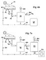
- Fig. 6a shows a further embodiment of the solar refrigeration unit 1 according to the invention, which in comparison to the embodiment according to Fig. 5 characterized in that the electrical energy generated by the at least one photovoltaic cell 11 of the collective collector 10 is provided not only the chiller 20 for their operation, but also an excess of electrical energy generated via an electrical interface 50 an external not shown here Power grid 51 is provided.
- Power grid 51 By a tempered feed of electrical energy into the external power grid 51, consequently, the profitability of the operation of the illustrated solar refrigeration unit 1 can be significantly increased.
- Fig. 6b shows a schematic representation of an alternative embodiment to that in Fig. 6a
- the at least one photovoltaic cell 11 of the collective collector 10 generated excess energy is not supplied to an external power grid, but is stored by means of a memory device 60 in electrical or chemical form.
- the refrigeration machine 20 included in the solar refrigeration unit 1 can also be supplied with electrical energy even if the solar irradiation does not suffice for the representation of a sufficient amount of electrical energy with the aid of the collective collector 10 is.
- Such conditions are conceivable, for example, in cloudy skies or at evening and morning times.
- the energy stored in the memory device 60 can also be used by other customers.
- Fig. 7a shows a schematic representation of another embodiment of the solar refrigeration unit according to the invention 1.
- the embodiment is here as a partial extension of in Fig. 6a and 6b shown embodiments shown.
- the present embodiment additionally comprises a high-temperature heat pump 82 which is adapted to heat dissipation 101 in the Fig. 6a and 6b shown chiller 20 as a heat transfer 102 to the high-temperature heat pump 82 to transmit.
- the high-temperature heat pump 82 also requires a supply of electrical energy, which can preferably be covered by the electrical energy generated by sufficient solar radiation by means of the collective collector 10.
- an electrical energy supply can additionally be covered from an external electrical power network 51, which is not further shown here.
- the external power grid 51 is symbolized by an interface 50.
- the high-temperature heat pump 82 allows to calorificize the fluid of the temperature T2 discharged from the refrigerator 20 and to produce a heat output 101 represented by a flow of a fluid of the temperature T3.
- the fluid delivered by the high-temperature heat pump 82 may in this case be identical or different to the fluid of the temperature T2 received by the refrigerating machine 20. In any case, however, the temperature T3 is greater than the temperature T2. Consequently, the consumer is compared to the embodiments of the solar refrigeration unit 1 according to Fig. 6a and Fig. 6b a heat output 101 higher heat content or higher temperature available. This is particularly advantageous for industrial processes as well as for the hot water treatment, since for this purpose the heat output of the temperature level T2 provided by the chiller 20 is usually insufficient.
- the heat output from chiller 20 and received by high temperature heat pump 82 is about 240 kW, and corresponds to a flow of fluid having a temperature T2 of about 42 ° C.
- the discharged from the high-temperature heat pump 82 fluid has approximately a temperature of 60 ° C to 100 ° C and a heat output of 300kW.
- the high-temperature heat pump 82 receives about 72 kW of additional electric power, which is covered to about 16 kW through the collective collector 10 and the rest of the external electrical power system 10.
- Fig. 7b shows a schematic representation of another embodiment of the solar refrigeration unit according to the invention 1.
- the present embodiment differs from the in Fig. 7a shown embodiment only in that instead of a high-temperature heat pump 82, an adsorption / absorption heat pump 83 is used to those in Figs. 6a and 6b, the heat output 102 of the refrigeration machine 20, which is represented by a flow of a fluid of temperature T2, to prepare a heat output 101, which is represented by a flow of a fluid of temperature T4.
- the discharged from the adsorption / absorption heat pump 83 fluid again coincide with the fluid, which in turn is discharged from the chiller 20.
- adsorption / absorption heat pump 83 again coincide with the fluid, which in turn is discharged from the chiller 20.
- the present embodiment requires a relatively lower supply of electrical energy for operation, which in ordinary sunlight can be easily covered by the electrical energy generated by the solar panel system 10 'or the collective collector 10. In the normal case, the electrical energy generation is even sufficient to save a portion of electrical energy not consumed by the solar refrigeration unit 1 with the aid of a storage device 60.
- the present adsorption / absorption heat pump 83 also requires a heat absorption 103, which is represented by a flow of a fluid of temperature T5 of sometimes more than 100 ° C. The fluid or heat can be taken from a waste heat system, a steam system or a hot water supply. In addition, even the direct firing of the adsorption / absorption heat pump 83 by the burning of fossil fuels is possible.
- the heat output 101 of the adsorption / absorption heat pump 83 is effected by the outflow of a fluid of temperature T4, which is approximately between 50 ° C and 60 ° C.
- the adsorption / absorption heat pump 83 receives a heat transfer 102 of a heat output of 240 kW of a fluid having a temperature T2 of approximately 45 ° C.
- a heat absorption 103 takes place from an external source of about 200 kW.
- the additionally recorded electrical supply power of the adsorption / absorption heat pump 83 is about 10 kW, with about 6 kW of electric solar energy generated by the solar collector system 10 'or the collective collector 10 is stored in the memory device 20.
- the heat output 101 of the adsorption / absorption heat pump 83 is about 440 kW and corresponds to the flow of a fluid of temperature T4, which is about 50 ° C to 60 ° C.
- Fig. 8 shows a schematic representation of another embodiment of the solar refrigeration unit 1 according to the invention, which in comparison to the in Fig. 6b shown solar refrigeration unit 1 further comprises a compression refrigeration 80.
- the illustrated compression refrigeration machine 80 is connected downstream of the storage device 60 for storing excessively generated electrical energy of the collective collector 10. If, for example, a cloud for supplying the chiller 20 insufficient electric power generation by the collective collector 10 can still be provided by the execution solar cooling unit 1 a cooling 100, which is generated by the Kompressionskarltemaschine 80.
- the power to the chiller 20 can be interrupted for this purpose.
- the output from the collective collector 10 to the chiller 20 thermal energy flow which is characterized by insufficient sunshine by a lower temperature level than the temperature level T1 reached in good sunshine, is delivered to the consumer.
- the storage device 60 may comprise a battery element.
- the storage device 60 may split excess generated current into a hydrogen and oxygen by a suitable splitting device 61 (not shown) and store at least the illustrated hydrogen in a storage container 62 (not shown herein).
- electrical energy may either be taken directly from the at least one battery element, or electrical energy generated from the hydrogen stored in the reservoir 62 by means of a fuel cell 63 (not shown herein) and provided to the compression refrigeration machine 80 for operation ,
- the storage device 60 included in the solar refrigeration unit 1 can also be included in a transportable arrangement device 70, which is not further shown here.
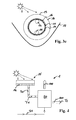
- Fig. 9 shows a further embodiment of the solar cooling unit 1 according to the invention, which is operated in the absence of sunlight, such as at night.
- the in Fig. 9 functional status stored in the memory device 60, excess energy generated during the day is retrieved and supplied to one or a plurality of cooling towers 81.
- a suitable cooling output 100 is provided by an evaporation effect, which can be discharged accordingly.
- the electrical energy consumption by the at least one cooling tower 81 is used This mainly to the operation of pumps or evaporation devices, such as fans.
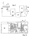
- Fig. 10 shows a further embodiment of the solar refrigeration unit 1 according to the invention in a sectional view from the side.
- the embodiment solar refrigeration unit 1 is hereby taken by a transportable arrangement device 70, which is designed as a container or shipping container. All components of the solar refrigeration unit 1, which do not require solar irradiation for operation, can be accommodated in the transportable arrangement device 70.
- a chiller 20 is accommodated, which is supplied via a fluid line system 30 by a not shown here solar collector system 10 'and a collective collector 10 not shown here with thermal energy.
- the present illustrated embodiment includes as another component, a compression refrigeration machine 80 and an expansion vessel 74, whose function is not to be performed in detail.
- Fig. 11 shows a side sectional view of the in Fig. 10 illustrated embodiment of the solar refrigeration unit 1 according to the invention, but in comparison to Fig. 10 in a section offset laterally with respect to the longitudinal extent of the transportable arrangement device 70.
- the illustrated solar refrigeration unit 1 also includes a cold storage 72 and a heat storage 73, which are provided for receiving the votes of the chiller 20 cold (refrigeration output 100) and heat (heat output 101). Accordingly, the thermal energy provided by the refrigerator 20 (negative as well as positive) can be latched and retrieved upon request.
Landscapes
- Engineering & Computer Science (AREA)
- Life Sciences & Earth Sciences (AREA)
- Sustainable Development (AREA)
- Mechanical Engineering (AREA)
- General Engineering & Computer Science (AREA)
- Sustainable Energy (AREA)
- Physics & Mathematics (AREA)
- Thermal Sciences (AREA)
- Chemical & Material Sciences (AREA)
- Combustion & Propulsion (AREA)
- Photovoltaic Devices (AREA)
Priority Applications (3)
| Application Number | Priority Date | Filing Date | Title |
|---|---|---|---|
| EP08167978A EP2169331A3 (fr) | 2008-09-30 | 2008-10-30 | Unité de refroidissement solaire |
| PCT/EP2009/061198 WO2010037607A2 (fr) | 2008-09-30 | 2009-08-31 | Unité frigorifique solaire |
| EP09782389A EP2344815A2 (fr) | 2008-09-30 | 2009-08-31 | Unité frigorifique solaire |
Applications Claiming Priority (2)
| Application Number | Priority Date | Filing Date | Title |
|---|---|---|---|
| EP08165550 | 2008-09-30 | ||
| EP08167978A EP2169331A3 (fr) | 2008-09-30 | 2008-10-30 | Unité de refroidissement solaire |
Publications (2)
| Publication Number | Publication Date |
|---|---|
| EP2169331A2 true EP2169331A2 (fr) | 2010-03-31 |
| EP2169331A3 EP2169331A3 (fr) | 2010-07-28 |
Family
ID=40029172
Family Applications (2)
| Application Number | Title | Priority Date | Filing Date |
|---|---|---|---|
| EP08167978A Withdrawn EP2169331A3 (fr) | 2008-09-30 | 2008-10-30 | Unité de refroidissement solaire |
| EP09782389A Withdrawn EP2344815A2 (fr) | 2008-09-30 | 2009-08-31 | Unité frigorifique solaire |
Family Applications After (1)
| Application Number | Title | Priority Date | Filing Date |
|---|---|---|---|
| EP09782389A Withdrawn EP2344815A2 (fr) | 2008-09-30 | 2009-08-31 | Unité frigorifique solaire |
Country Status (3)
| Country | Link |
|---|---|
| EP (2) | EP2169331A3 (fr) |
| DE (1) | DE202008014419U1 (fr) |
| WO (1) | WO2010037607A2 (fr) |
Cited By (5)
| Publication number | Priority date | Publication date | Assignee | Title |
|---|---|---|---|---|
| ES2444990R1 (es) * | 2012-05-25 | 2014-03-19 | Gonzalo José BRUN GRESA | Panel solar híbrido plano para la producción de energía eléctrica y energía térmica con sistema de mejora del rendimiento global mediante cubierta transparente aislante CTA |
| CN105423615A (zh) * | 2015-12-11 | 2016-03-23 | 浙江陆特能源科技股份有限公司 | 三盘管太阳能冷暖装置 |
| US11421920B2 (en) | 2019-04-25 | 2022-08-23 | King Fahd University Of Petroleum And Minerals | Solar-powered adsorption chiller operable in the absence of sunlight |
| US11530852B2 (en) | 2014-11-25 | 2022-12-20 | B. Medical Systems S.a.r.l. | Cooling device |
| EP4283203A4 (fr) * | 2021-01-21 | 2024-12-11 | Beijing Jingkelun Engineering Design and Research Institute Co., Ltd. | Système de climatisation centrale de froid et de chaleur reposant sur une collecte de chaleur par rayonnement et une dissipation de chaleur par rayonnement |
Families Citing this family (9)
| Publication number | Priority date | Publication date | Assignee | Title |
|---|---|---|---|---|
| IT1394707B1 (it) * | 2009-05-29 | 2012-07-13 | Olcese | Dispositivo compressore per impianti di condizionamento ambientale |
| IT1399061B1 (it) * | 2010-03-22 | 2013-04-05 | Chiappa | Centrale energetica compatta con sistema integrato di fonti rinnovabili atto a garantire autosufficienza energetica ad un impianto termico |
| DE102010003462A1 (de) * | 2010-03-30 | 2011-10-06 | Bam Deutschland Ag | Temperiersystem |
| AT12694U1 (de) * | 2011-03-21 | 2012-10-15 | Egg Robert Ing | Mobile Wassertemperiereinheit für Gebäude |
| GR20110100285A (el) * | 2011-05-12 | 2013-01-22 | Αλεξανδρος Χρηστου Παπαδοπουλος | Τεχνολογια ανεξοδης διεισδυσης της ηλιακης τριπαραγωγης στην αγορα ενεργειας μεσω του ηλιακου ψαλιδισμου αιχμης |
| DE102012019525A1 (de) * | 2012-10-05 | 2014-02-13 | Maike Brabenec | Photovoltaisch-thermisches Hybrid-Solarsystem |
| DE102015211473A1 (de) | 2015-06-22 | 2016-12-22 | Fraunhofer-Gesellschaft zur Förderung der angewandten Forschung e.V. | Vorrichtung und Verfahren zur Klimatisierung eines Raumes |
| CN109237677B (zh) * | 2018-09-27 | 2020-06-30 | 华中科技大学 | 一种集热-辐射装置及其制冷系统 |
| DE102023136386A1 (de) | 2023-12-21 | 2025-06-26 | interpanel GmbH | Wärmetauscherpaneel zum Temperieren von Gebäuderäumen |
Citations (1)
| Publication number | Priority date | Publication date | Assignee | Title |
|---|---|---|---|---|
| DE3923821A1 (de) | 1989-07-19 | 1991-01-24 | Otto Dipl Phys Spormann | Kollektor zur gewinnung von energie aus der strahlung der sonne |
Family Cites Families (14)
| Publication number | Priority date | Publication date | Assignee | Title |
|---|---|---|---|---|
| JPS5862455A (ja) * | 1981-10-07 | 1983-04-13 | Fuji Electric Corp Res & Dev Ltd | 太陽エネルギコレクタ |
| JPS5915766A (ja) * | 1982-07-19 | 1984-01-26 | Toshiba Corp | 太陽エネルギ−利用装置 |
| DE4111319A1 (de) * | 1991-04-08 | 1992-10-15 | Siemens Ag | Klimaanlage |
| DE9201949U1 (de) * | 1992-02-12 | 1993-06-09 | Geist, André, 2000 Hamburg | Strahlungsenergieabsorber |
| ES2137349T3 (es) * | 1992-11-25 | 1999-12-16 | John Beavis Lasich | Produccion de hidrogeno de rendimiento elevado a partir de radiacion solar. |
| DE4433428C2 (de) * | 1994-09-20 | 2002-08-01 | Inst Luft Kaeltetech Gem Gmbh | Verfahren zur Energieversorgung von Klimageräten |
| DE29601105U1 (de) * | 1996-01-23 | 1997-05-22 | Bauer, Heinrich, 67661 Kaiserslautern | Vorrichtung zur Gewinnung von Energie aus Sonnenlicht mit mindestens einem Solarkollektor |
| NL1006838C2 (nl) * | 1997-08-25 | 1999-03-04 | Univ Eindhoven Tech | Paneelvormige hybride fotovoltaïsche/thermische inrichting. |
| DE29811199U1 (de) * | 1998-06-23 | 1998-09-17 | Bartelsen, Bernd, Dipl.-Ing., 31785 Hameln | Gasdichtes Gehäuse zur Aufnahme von solarelektrischen Wandlern |
| US6546743B1 (en) * | 2002-07-02 | 2003-04-15 | Marcus Ray Sullivan | Mobile cooling apparatus |
| DE102005054364A1 (de) * | 2005-11-15 | 2007-05-16 | Durlum Leuchten | Solarkollektor mit Kältemaschine |
| US20070157922A1 (en) * | 2005-12-29 | 2007-07-12 | United Technologies Corporation | Integrated electrical and thermal energy solar cell system |
| DE202007010901U1 (de) * | 2007-08-06 | 2007-12-27 | Brabenec, Maike | Hybridkollektor |
| DE202007012724U1 (de) * | 2007-09-11 | 2007-12-06 | Institut für Luft- und Kältetechnik gGmbH | Klimatisierter Container |
-
2008
- 2008-10-30 EP EP08167978A patent/EP2169331A3/fr not_active Withdrawn
- 2008-10-30 DE DE202008014419U patent/DE202008014419U1/de not_active Expired - Lifetime
-
2009
- 2009-08-31 EP EP09782389A patent/EP2344815A2/fr not_active Withdrawn
- 2009-08-31 WO PCT/EP2009/061198 patent/WO2010037607A2/fr not_active Ceased
Patent Citations (1)
| Publication number | Priority date | Publication date | Assignee | Title |
|---|---|---|---|---|
| DE3923821A1 (de) | 1989-07-19 | 1991-01-24 | Otto Dipl Phys Spormann | Kollektor zur gewinnung von energie aus der strahlung der sonne |
Cited By (7)
| Publication number | Priority date | Publication date | Assignee | Title |
|---|---|---|---|---|
| ES2444990R1 (es) * | 2012-05-25 | 2014-03-19 | Gonzalo José BRUN GRESA | Panel solar híbrido plano para la producción de energía eléctrica y energía térmica con sistema de mejora del rendimiento global mediante cubierta transparente aislante CTA |
| US11530852B2 (en) | 2014-11-25 | 2022-12-20 | B. Medical Systems S.a.r.l. | Cooling device |
| EP3224552B1 (fr) * | 2014-11-25 | 2024-02-07 | B Medical Systems S.à r.l. | Dispositif de refroidissement |
| CN105423615A (zh) * | 2015-12-11 | 2016-03-23 | 浙江陆特能源科技股份有限公司 | 三盘管太阳能冷暖装置 |
| US11421920B2 (en) | 2019-04-25 | 2022-08-23 | King Fahd University Of Petroleum And Minerals | Solar-powered adsorption chiller operable in the absence of sunlight |
| EP4283203A4 (fr) * | 2021-01-21 | 2024-12-11 | Beijing Jingkelun Engineering Design and Research Institute Co., Ltd. | Système de climatisation centrale de froid et de chaleur reposant sur une collecte de chaleur par rayonnement et une dissipation de chaleur par rayonnement |
| US12510258B2 (en) | 2021-01-21 | 2025-12-30 | Beijing Jingkelun Engineering Design and Research Institute Co., Ltd. | Radiation heat dissipation and radiation heat collection-based cold and hot central air conditioning system |
Also Published As
| Publication number | Publication date |
|---|---|
| WO2010037607A4 (fr) | 2010-10-07 |
| DE202008014419U1 (de) | 2009-01-15 |
| EP2169331A3 (fr) | 2010-07-28 |
| EP2344815A2 (fr) | 2011-07-20 |
| WO2010037607A3 (fr) | 2010-08-12 |
| WO2010037607A2 (fr) | 2010-04-08 |
Similar Documents
| Publication | Publication Date | Title |
|---|---|---|
| EP2169331A2 (fr) | Unité de refroidissement solaire | |
| EP2694885B1 (fr) | Dispositif et procédé de conversion d'énergie solaire rayonnante en courant électrique et/ou chaleur | |
| DE2520639A1 (de) | Anlage zur stromerzeugung | |
| WO2000008690A2 (fr) | Equipement photovoltaique | |
| DE102008009477A1 (de) | Solarthermische, thermoelektrische Stromerzeugungseinrichtung sowie Verfahren zu deren Betrieb | |
| EP2217866A2 (fr) | Système permettant l'utilisation de l'énergie solaire et pourvu d'un dispositif de dissipation de la chaleur dans le milieu ambiant, procédé de fonctionnement du système et utilisation | |
| DE102010000137A1 (de) | Solar-Kälteeinheit | |
| WO2013092394A2 (fr) | Dispositif et procédé de production directe d'énergie électrique à partir d'énergie thermique | |
| EP3485214B1 (fr) | Dispositif et système d'accumulation d'énergie | |
| DE602006000906T2 (de) | Sonnenkollektor mit Konzentration | |
| DE19604356C2 (de) | Verfahren und Vorrichtung zur Gewinnung von thermischer Energie aus solarer Energie | |
| EP2362935A2 (fr) | Procede et dispositif de recuperation d'energie thermique, notamment pour la production de courant electrique | |
| DE10034683C1 (de) | Kompakte Solaranlage zur Brauchwassererwärmung | |
| WO2010127661A2 (fr) | Installation solaire pour la production d'énergie électrique et thermique | |
| EP3147585B1 (fr) | Ballon tampon et système de production de chaleur doté d'un tel ballon tampon | |
| WO2009080305A2 (fr) | Procédé et dispositif de production d'énergie électrique | |
| DE19614787A1 (de) | Gebäudeklimatisierungssystem mit Einrichtungen zur Konzentration von Sonnenstrahlung | |
| DE102016001350B4 (de) | Verfahren und Vorrichtung zur Bereitstellung von Raumwärme und Warmwasser durch Nutzung solarer Strahlungsenergie | |
| WO2009043334A2 (fr) | Absorbeur d'énergie air-solaire | |
| DE19923196A1 (de) | Rekuperatives selektives Flüssigkeitsfilter für Photovoltaikmodule | |
| US20140202447A1 (en) | Nitrogen based thermal storage medium | |
| EP3830495B1 (fr) | Procédé d'isolation d'une unité de traitement et unité de traitement dotée d'une zone d'isolation | |
| DE202012009151U1 (de) | Erweiterte Wärmeenergieversorgungsanlage ,,Solarwärmemanager" | |
| WO2003026109A2 (fr) | Procede et dispositif de transformation d'energie | |
| EP4328517A1 (fr) | Dispositif de collecte d'énergie solaire, collecteur de chaleur, installation de production de chaleur et son procédé de commande |
Legal Events
| Date | Code | Title | Description |
|---|---|---|---|
| PUAI | Public reference made under article 153(3) epc to a published international application that has entered the european phase |
Free format text: ORIGINAL CODE: 0009012 |
|
| AK | Designated contracting states |
Kind code of ref document: A2 Designated state(s): AT BE BG CH CY CZ DE DK EE ES FI FR GB GR HR HU IE IS IT LI LT LU LV MC MT NL NO PL PT RO SE SI SK TR |
|
| AX | Request for extension of the european patent |
Extension state: AL BA MK RS |
|
| RIC1 | Information provided on ipc code assigned before grant |
Ipc: F24F 1/04 20060101ALI20100304BHEP Ipc: H01L 31/058 20060101ALI20100304BHEP Ipc: F25B 27/00 20060101ALI20100304BHEP Ipc: F24F 5/00 20060101ALI20100304BHEP Ipc: F24D 11/00 20060101ALI20100304BHEP Ipc: F24J 2/12 20060101ALI20100304BHEP Ipc: F24J 2/05 20060101AFI20081201BHEP |
|
| PUAL | Search report despatched |
Free format text: ORIGINAL CODE: 0009013 |
|
| AK | Designated contracting states |
Kind code of ref document: A3 Designated state(s): AT BE BG CH CY CZ DE DK EE ES FI FR GB GR HR HU IE IS IT LI LT LU LV MC MT NL NO PL PT RO SE SI SK TR |
|
| AX | Request for extension of the european patent |
Extension state: AL BA MK RS |
|
| AKY | No designation fees paid | ||
| STAA | Information on the status of an ep patent application or granted ep patent |
Free format text: STATUS: THE APPLICATION IS DEEMED TO BE WITHDRAWN |
|
| 18D | Application deemed to be withdrawn |
Effective date: 20110129 |