EP2169336A2 - Appareil de refroidissement ménager doté de parois latérales - Google Patents
Appareil de refroidissement ménager doté de parois latérales Download PDFInfo
- Publication number
- EP2169336A2 EP2169336A2 EP09170848A EP09170848A EP2169336A2 EP 2169336 A2 EP2169336 A2 EP 2169336A2 EP 09170848 A EP09170848 A EP 09170848A EP 09170848 A EP09170848 A EP 09170848A EP 2169336 A2 EP2169336 A2 EP 2169336A2
- Authority
- EP
- European Patent Office
- Prior art keywords
- housing
- force
- refrigerating appliance
- side walls
- distributors
- Prior art date
- Legal status (The legal status is an assumption and is not a legal conclusion. Google has not performed a legal analysis and makes no representation as to the accuracy of the status listed.)
- Ceased
Links
- 238000001816 cooling Methods 0.000 title description 3
- 239000004033 plastic Substances 0.000 claims abstract description 5
- 229920003023 plastic Polymers 0.000 claims abstract description 5
- 239000004743 Polypropylene Substances 0.000 claims abstract description 4
- -1 polypropylene Polymers 0.000 claims abstract description 4
- 229920001155 polypropylene Polymers 0.000 claims abstract description 4
- 125000006850 spacer group Chemical group 0.000 claims description 8
- 239000011810 insulating material Substances 0.000 claims description 3
- 229910052623 talc Inorganic materials 0.000 claims description 3
- 235000012222 talc Nutrition 0.000 claims description 3
- 239000000454 talc Substances 0.000 claims description 3
- 239000000463 material Substances 0.000 description 7
- 239000008186 active pharmaceutical agent Substances 0.000 description 5
- 239000006260 foam Substances 0.000 description 5
- 238000005057 refrigeration Methods 0.000 description 4
- 238000009413 insulation Methods 0.000 description 3
- 239000000835 fiber Substances 0.000 description 2
- 238000003780 insertion Methods 0.000 description 2
- 230000037431 insertion Effects 0.000 description 2
- 230000002787 reinforcement Effects 0.000 description 2
- 229910000831 Steel Inorganic materials 0.000 description 1
- 239000000853 adhesive Substances 0.000 description 1
- 238000004026 adhesive bonding Methods 0.000 description 1
- 230000001070 adhesive effect Effects 0.000 description 1
- 239000000969 carrier Substances 0.000 description 1
- 238000011161 development Methods 0.000 description 1
- 230000018109 developmental process Effects 0.000 description 1
- 230000002349 favourable effect Effects 0.000 description 1
- 239000002657 fibrous material Substances 0.000 description 1
- 238000002347 injection Methods 0.000 description 1
- 239000007924 injection Substances 0.000 description 1
- 238000009434 installation Methods 0.000 description 1
- 238000004519 manufacturing process Methods 0.000 description 1
- 239000010959 steel Substances 0.000 description 1
- 230000000007 visual effect Effects 0.000 description 1
Images

Classifications
-
- F—MECHANICAL ENGINEERING; LIGHTING; HEATING; WEAPONS; BLASTING
- F25—REFRIGERATION OR COOLING; COMBINED HEATING AND REFRIGERATION SYSTEMS; HEAT PUMP SYSTEMS; MANUFACTURE OR STORAGE OF ICE; LIQUEFACTION SOLIDIFICATION OF GASES
- F25D—REFRIGERATORS; COLD ROOMS; ICE-BOXES; COOLING OR FREEZING APPARATUS NOT OTHERWISE PROVIDED FOR
- F25D23/00—General constructional features
- F25D23/06—Walls
- F25D23/062—Walls defining a cabinet
- F25D23/063—Walls defining a cabinet formed by an assembly of panels
-
- F—MECHANICAL ENGINEERING; LIGHTING; HEATING; WEAPONS; BLASTING
- F25—REFRIGERATION OR COOLING; COMBINED HEATING AND REFRIGERATION SYSTEMS; HEAT PUMP SYSTEMS; MANUFACTURE OR STORAGE OF ICE; LIQUEFACTION SOLIDIFICATION OF GASES
- F25D—REFRIGERATORS; COLD ROOMS; ICE-BOXES; COOLING OR FREEZING APPARATUS NOT OTHERWISE PROVIDED FOR
- F25D2400/00—General features of, or devices for refrigerators, cold rooms, ice-boxes, or for cooling or freezing apparatus not covered by any other subclass
- F25D2400/32—Removal, transportation or shipping of refrigerating devices from one location to another
Definitions
- the invention relates to a household refrigerator with a lateral walls having housing according to the preamble of claim 1.
- the invention is based on the problem of achieving an improvement here.
- a household cooling device is created in which parts of the housing, in particular lateral walls, can be embodied in a reduced material thickness or an overall lighter material and thus result in a reduced material expenditure and a reduced weight.
- the force distributors at least a portion of the force acting on the side walls during clamping forces are derived - for example, in profiles which are part of the side walls transversely connecting support structure, and / or in a rear wall and / or in a bottom plate or an upper cover plate, the may also be part of a cross-connecting support structure.
- a particularly good distribution of force is achieved when the force distributors are each formed three-dimensional and have flange-like connecting surfaces both to the side walls and to a transversely connecting carrier structure as well as to a horizontal under or covering structure. Then, a force distribution in both the transverse and in the longitudinal direction of the housing is made possible, so that each individual force component is relatively small and therefore only a comparatively small material thickness is needed to accommodate these force components.
- An advantageous bonding of the power distributor with the side walls ensures an efficient introduction of force from the side walls in the power distributor - better than about a point introduction, for example via screws.
- brackets of household refrigerators are power distributors at least the upper housing corners assigned to there force splitting of the sidewalls introduced forces in one hand a cross connector, for example a front rail and / or a rear wall and on the other hand in longitudinal structures, for example, in a upper plate body to reach.
- a cross connector for example a front rail and / or a rear wall
- longitudinal structures for example, in a upper plate body to reach.
- the flange-like connection surfaces may be large in relation to overlapping attachment corners with which the side walls and cross-connecting structures are screwed, riveted or similarly fastened together.
- the actual attachment of the parts of the housing to each other must not be changed by the invention.
- the housing can be low cost even without the power distributor and its parts be held together.
- the self-weighting force distributors are then introduced only in addition to the supporting structures of the housing optimizing components.
- the force distributors can be glued on their outer sides with the side walls and / or cross-connecting structures over the entire surface and thus lie invisibly within these structures. Furthermore, it is favorable for a good splitting of forces if the force distributors have on their insides a surface enlargement, in particular a ribbing, for large-area connection to an insulating material within the housing. Then also a part of the external forces can be introduced into such foam insulation; In addition, it is also ensured in the field of such power distributors that the insulation does not break off from these and can be carried out in the corners.
- Such power distributors can be produced inexpensively as dimensionally stable plastic parts, for example made of polypropylene, possibly reinforced by talcum.
- a fiber reinforcement which penetrates the component in whole or in part is also possible depending on the requirement profile.
- the assembly is particularly facilitated when power distributor for four upper housing corners are formed similar. A wrong assembly is then prevented.
- the flange-like connecting surfaces in the vertical direction and in horizontal transverse and in horizontal longitudinal direction can have an extension of 5 to 15 centimeters edge length and thus ensure a large contact surface.
- a particularly versatile embodiment of the invention provides that the force distributors are equipped with additional functions, for example, such that the upper side rear housing corners associated force distributors are provided with rear spacers for Abstandungsschutz of the housing relative to a furniture or building wall. Then it is ensured in particular alone on this power distributor that a lying behind the rear wall outer heat exchanger always has a minimum distance to the furniture or housing, without requiring separate components for this purpose.
- the spacers may be integrally and integrally formed with the rear power distributors.
- Such force distributors can also with back, an edge region of a Be provided heat exchanger holding retaining pieces, so that a separate upper attachment of the heat exchanger can be saved.
- these upper rear power distributors can advantageously also be provided with rear gripping pieces for transporting the household refrigerating appliance, which for example form recessed grip recesses and, since they protrude to the rear, do not impair the visual appearance.
- FIG. 1 shown household refrigeration unit HK is provided at its transverse sides with side walls S, which via these cross-connecting support structures QT communicate with each other and form a housing G.
- These transversely connecting support structures QT adjoin the side walls S at at least upper and lower corner regions and are connected therewith, for example screwed or hidden, so that form-fitting connections result.
- the support structures QT here include, inter alia, an upper transverse profile 1 and a lower, also transversely extending baseboard 2.
- the upper corner areas associated with the side walls area-connected force distributor KV could additionally or alternatively - depending on training in the lower area - also be assigned power distributor.
- the power distributors KV of which here different configurations KV 1, KV2, KV3 and KV4 are shown, introduced into the side walls S forces in at least the transversely connecting support structures QT can be introduced, possibly also in longitudinal profiles, for example, bevelled on the upper side Flanges 3 of the side walls S reach under and here are not visible.
- the front power distributor KV1 according to FIG. 1 could also be connected to each other on the cross section 1 in one piece, as well as the rear two force distributor KV2.
- the force distributors KV1, KV2, KV3, KV4 shown in the drawing are formed three-dimensionally and each have flange-like connecting surfaces 4 both to the side walls S and to a cross-connecting support structure QT as well as to a horizontal under or covering structure, for example one covering plate - not shown here - on.
- the force distributors KV engage under the side walls S and are adhesively bonded to these over the outer connecting surfaces 4 over the entire surface.
- This underreaching is not shown in the drawing, since otherwise the force distributor KV would not be seen there.
- the force distributors KV outside on the side walls S and the front cross section 1. This is basically possible.
- the force distributors KV are overlapped on the outside by the side walls S as well as by the transverse profile 1 and are glued into them over the outer sides of their flange-like connecting surfaces 4.
- the power distributor KV must then not be visible even from the outside.
- connecting surfaces 4 are large in relation to overlapping fastening corners with which the side walls S and cross-connecting structures QT are connected to one another anyway, for example via screwing or riveting or the like.
- the housing G can therefore, as before, be stable even without the separate force distributors KV and its parts connected to one another.
- the force distributors KV form separate and additional components.
- the arrangement of the separate force distributor KV within the outer shell of the housing G is particularly well possible if they are provided on their respective inner side with a surface enlargement, such as a ribbing 5, for large-area connection with an insulating material within the housing G.
- These ribs are in FIG. 1 indicated, where they can also point outward in the position of the force transmitter shown there, if outside a layer of insulating foam and then further walls would be applied.
- the ribs 5 inwardly, so that the force distribution KV total between an insulating foam and a supporting outer structure, namely the side walls S, a transverse connecting support structure QT and / or a horizontal cover plate, are arranged.
- All power distributors KV are formed as inherently rigid plastic parts, for example made of polypropylene, possibly reinforced by talc or a fiber material. With the high intrinsic stability, the force distributors KV reinforce the housing G so that the wall thicknesses of the side walls S can be reduced, for example from 0.7 to 0.4 millimeters.
- the flange-like connecting surfaces 4 in the vertical direction and in horizontal transverse and horizontal longitudinal direction can have an extension of 5 to 15 or more centimeters edge length and thus also stabilize large areas of the housing.
- the extension can be the same size in three spatial directions, as in FIG. 1 is indicated. In this respect, there is a threefold symmetry. With the reduction in wall thicknesses significant weight and material savings is achieved.
- the force distributors KV for four upper housing corners can be made the same - different, as shown here.
- the force distributors KV are equipped with advantageous additional functions and have a different design:
- the spacers DS may be integrally formed with the power distributors KV4 and in total, for example, as injection molded parts. A coextrusion of different plastics for areas of different mechanical requirements is possible.
- the upper side rear housing corners associated force distributor KV4 can be provided with back grips 7 for transporting the household cooling device HK. These are designed here as recessed grip recesses so that the household refrigerator can be easily grasped.
- the one-piece design and full-surface bonding of the power distributor KV4 there is no risk of tearing, since the forces introduced here as well as the above-mentioned brackets divided in several directions and thus distributed to several units of the housing G.
- Grips 7 are also formed, but without additional spacers 5 form.
- force distributors mounted on the upper side of the rear housing corners can also be provided on their rear sides with an upper edge region of a heat exchanger 6 holding holding pieces, which are not shown here in the drawing.
- the edge region of the heat exchanger 6 can engage, for example, in the holding pieces and thus be held securely without a further assembly step, such as a screw.
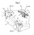
- FIG. 3 is, however, shown as a further embodiment, that those force distributors KV3, KV4, the upper-side housing corners are assigned, additional attachment lugs 8, here upwardly projecting pins, for the attachment of a covering in the top Plate body - not shown - wear, which are also integrally formed with the power distributors KV3, KV4.
- additional attachment lugs 8 here upwardly projecting pins, for the attachment of a covering in the top Plate body - not shown - wear, which are also integrally formed with the power distributors KV3, KV4.
- a separate fiber reinforcement is possible without having to cancel the one-piece nature of the power distributor KV.
- the force distributors KV3 assigned to the upper side or lower side corners of the housing can carry fastening lugs 9 for door bearing angles.
- these fastening lugs 9 are formed by insertion openings for such an angle, in which a horizontal leg can be inserted, while the vertical leg of the angle, for example, can be bolted to a front side frame.
- FIG. 3 is additionally shown that upper-side housing corners associated force distributor KV3 with attachment lugs 10, 11 for example, for insertion of flanges of side walls S and / or cross-connecting carriers QT, such as the front profiles 1, are provided.
- these parts also find stops that ensure their exact position with respect to the power distributor KV3, KV4.
- force distributors can also have recesses for the passage of regulators, switches or displays - not shown here.
- All KV power distributors can be used for a wide range of household refrigeration appliances HK, without having to have different dimensions themselves.
- Zum Gluing the foam can be sufficient in itself, without the need for a separate adhesive.
Landscapes
- Engineering & Computer Science (AREA)
- Chemical & Material Sciences (AREA)
- Combustion & Propulsion (AREA)
- Physics & Mathematics (AREA)
- Mechanical Engineering (AREA)
- Thermal Sciences (AREA)
- General Engineering & Computer Science (AREA)
- Refrigerator Housings (AREA)
Applications Claiming Priority (1)
| Application Number | Priority Date | Filing Date | Title |
|---|---|---|---|
| DE200810042408 DE102008042408A1 (de) | 2008-09-26 | 2008-09-26 | Haushaltskühlgerät mit Seitenwandungen |
Publications (2)
| Publication Number | Publication Date |
|---|---|
| EP2169336A2 true EP2169336A2 (fr) | 2010-03-31 |
| EP2169336A3 EP2169336A3 (fr) | 2017-09-20 |
Family
ID=41395916
Family Applications (1)
| Application Number | Title | Priority Date | Filing Date |
|---|---|---|---|
| EP09170848.7A Ceased EP2169336A3 (fr) | 2008-09-26 | 2009-09-21 | Appareil de refroidissement ménager doté de parois latérales |
Country Status (2)
| Country | Link |
|---|---|
| EP (1) | EP2169336A3 (fr) |
| DE (1) | DE102008042408A1 (fr) |
Cited By (2)
| Publication number | Priority date | Publication date | Assignee | Title |
|---|---|---|---|---|
| ITRM20130181A1 (it) * | 2013-03-27 | 2014-09-28 | Ind Scaffalature Arredamenti Isa S R L | Banco frigorifero e procedimento di montaggio di tale banco |
| US20230349628A1 (en) * | 2020-01-07 | 2023-11-02 | Lg Electronics Inc. | Refrigerator |
Family Cites Families (5)
| Publication number | Priority date | Publication date | Assignee | Title |
|---|---|---|---|---|
| DE4243135A1 (de) * | 1992-12-19 | 1994-06-30 | Blohm Voss Ag | Verfahren und Vorrichtung zur Verbindung |
| US6773082B2 (en) * | 2002-01-28 | 2004-08-10 | Daewoo Electronics Corp. | Refrigerator using EPS insulating material |
| US7014283B2 (en) * | 2002-07-16 | 2006-03-21 | Maytag Corporation | Localized reinforcement system for refrigerator cabinet |
| DE102005057150A1 (de) * | 2005-11-30 | 2007-06-06 | BSH Bosch und Siemens Hausgeräte GmbH | Kühl- bzw. Gefrierschrank mit Verstärkungsrahmen |
| DE102007011113A1 (de) * | 2007-03-07 | 2008-09-11 | BSH Bosch und Siemens Hausgeräte GmbH | Gehäuse für ein Kältegerät |
-
2008
- 2008-09-26 DE DE200810042408 patent/DE102008042408A1/de not_active Withdrawn
-
2009
- 2009-09-21 EP EP09170848.7A patent/EP2169336A3/fr not_active Ceased
Non-Patent Citations (1)
| Title |
|---|
| None * |
Cited By (4)
| Publication number | Priority date | Publication date | Assignee | Title |
|---|---|---|---|---|
| ITRM20130181A1 (it) * | 2013-03-27 | 2014-09-28 | Ind Scaffalature Arredamenti Isa S R L | Banco frigorifero e procedimento di montaggio di tale banco |
| WO2014155398A1 (fr) * | 2013-03-27 | 2014-10-02 | Industrie Scaffalature Arredamenti Isa S.R.L. | Bac de refroidisseur et procédé d'assemblage dudit bac |
| US20230349628A1 (en) * | 2020-01-07 | 2023-11-02 | Lg Electronics Inc. | Refrigerator |
| US12222156B2 (en) * | 2020-01-07 | 2025-02-11 | Lg Electronics Inc. | Refrigerator |
Also Published As
| Publication number | Publication date |
|---|---|
| DE102008042408A1 (de) | 2010-04-01 |
| EP2169336A3 (fr) | 2017-09-20 |
Similar Documents
| Publication | Publication Date | Title |
|---|---|---|
| EP1957906B1 (fr) | Refrigerateur et/ou congelateur a cadre de renfort | |
| WO2007118787A1 (fr) | Appareil de réfrigération à dispositif distributeur | |
| DE102010016722A1 (de) | Schaltschranksockel | |
| EP2264387A2 (fr) | Appareil de réfrigération et/ou de refroidissement | |
| EP2429343A1 (fr) | Paroi de meuble et meuble | |
| EP1387991A1 (fr) | Element de separation de compartiment | |
| DE102017106299B4 (de) | Multifunktionaler Träger einer Unterkonstruktion eines Fahrzeugs | |
| EP3545793B1 (fr) | Meuble formé de pièces profilées s'étendant verticalement et horizontalement ainsi que meuble pourvu d'au moins deux parois latérales | |
| EP1882140B1 (fr) | Contenant interne d'un appareil refrigerant | |
| EP2169336A2 (fr) | Appareil de refroidissement ménager doté de parois latérales | |
| EP3191779B1 (fr) | Appareil frigorifique avec caisson extractible | |
| EP2290308B1 (fr) | Appareil frigorifique | |
| EP2524855B1 (fr) | Structure pour un véhicule utilitaire | |
| DE102010038483A1 (de) | Einbaufähiges Haushaltsgerät | |
| DE4307088C1 (de) | Aufnahmevorrichtung für Geräte und/oder Gegenstände im Fahrgastraum eines Kraftfahrzeugs | |
| DE102012108688A1 (de) | Säulenprofileinrichtung und Bodenprofil zum Einbau in einem Fahrzeug sowie Regalsystem hierzu | |
| DE60223494T2 (de) | Lösbare trennwand | |
| EP1095232A1 (fr) | Compartiment de rangement | |
| EP2557962A1 (fr) | Élément de tiroir pour structures d'étagère, en particulier pour l'adaptation à l'intérieur de véhicules commerciaux équipés d'accessoires | |
| DE102010039742A1 (de) | Befestigungsanordnung in einem Kältegerät | |
| DE202009017855U1 (de) | Verpackungseinrichtung für großflächige Solarmodule | |
| DE202006006507U1 (de) | Anordnung für eine Scheibenbefestigung und/oder Raumabtrennung, insbesondere eine Duschabtrennung oder Dampfkabine | |
| EP0094037B1 (fr) | Cabine | |
| DE102006023169B4 (de) | Bauelement für einen Nutzfahrzeugaufbau, Nutzfahrzeug mit einem derartigen Bauelement und Verfahren zur Herstellung eines derartigen Bauelementes | |
| EP3388317A1 (fr) | Construction de véhicule frigorifique |
Legal Events
| Date | Code | Title | Description |
|---|---|---|---|
| PUAI | Public reference made under article 153(3) epc to a published international application that has entered the european phase |
Free format text: ORIGINAL CODE: 0009012 |
|
| AK | Designated contracting states |
Kind code of ref document: A2 Designated state(s): AT BE BG CH CY CZ DE DK EE ES FI FR GB GR HR HU IE IS IT LI LT LU LV MC MK MT NL NO PL PT RO SE SI SK SM TR |
|
| RAP1 | Party data changed (applicant data changed or rights of an application transferred) |
Owner name: BSH HAUSGERAETE GMBH |
|
| PUAL | Search report despatched |
Free format text: ORIGINAL CODE: 0009013 |
|
| AK | Designated contracting states |
Kind code of ref document: A3 Designated state(s): AT BE BG CH CY CZ DE DK EE ES FI FR GB GR HR HU IE IS IT LI LT LU LV MC MK MT NL NO PL PT RO SE SI SK SM TR |
|
| RIC1 | Information provided on ipc code assigned before grant |
Ipc: F25D 23/06 20060101AFI20170814BHEP |
|
| 17P | Request for examination filed |
Effective date: 20180320 |
|
| RBV | Designated contracting states (corrected) |
Designated state(s): AT BE BG CH CY CZ DE DK EE ES FI FR GB GR HR HU IE IS IT LI LT LU LV MC MK MT NL NO PL PT RO SE SI SK SM TR |
|
| 17Q | First examination report despatched |
Effective date: 20190509 |
|
| STAA | Information on the status of an ep patent application or granted ep patent |
Free format text: STATUS: THE APPLICATION HAS BEEN REFUSED |
|
| 18R | Application refused |
Effective date: 20191108 |