EP2170011A2 - Fahrzeuglampe - Google Patents
Fahrzeuglampe Download PDFInfo
- Publication number
- EP2170011A2 EP2170011A2 EP09011787A EP09011787A EP2170011A2 EP 2170011 A2 EP2170011 A2 EP 2170011A2 EP 09011787 A EP09011787 A EP 09011787A EP 09011787 A EP09011787 A EP 09011787A EP 2170011 A2 EP2170011 A2 EP 2170011A2
- Authority
- EP
- European Patent Office
- Prior art keywords
- light
- light source
- emitting diodes
- current
- source block
- Prior art date
- Legal status (The legal status is an assumption and is not a legal conclusion. Google has not performed a legal analysis and makes no representation as to the accuracy of the status listed.)
- Withdrawn
Links
- 230000005856 abnormality Effects 0.000 claims abstract description 54
- 239000004065 semiconductor Substances 0.000 claims abstract description 49
- 239000011159 matrix material Substances 0.000 claims description 9
- 238000012544 monitoring process Methods 0.000 claims description 8
- 230000010355 oscillation Effects 0.000 claims description 8
- 238000001514 detection method Methods 0.000 description 12
- 239000003990 capacitor Substances 0.000 description 4
- 230000002159 abnormal effect Effects 0.000 description 3
- 238000010586 diagram Methods 0.000 description 3
- 230000000694 effects Effects 0.000 description 2
- 230000000994 depressogenic effect Effects 0.000 description 1
- 238000004020 luminiscence type Methods 0.000 description 1
Images

Classifications
-
- B—PERFORMING OPERATIONS; TRANSPORTING
- B60—VEHICLES IN GENERAL
- B60Q—ARRANGEMENT OF SIGNALLING OR LIGHTING DEVICES, THE MOUNTING OR SUPPORTING THEREOF OR CIRCUITS THEREFOR, FOR VEHICLES IN GENERAL
- B60Q11/00—Arrangement of monitoring devices for devices provided for in groups B60Q1/00 - B60Q9/00
- B60Q11/005—Arrangement of monitoring devices for devices provided for in groups B60Q1/00 - B60Q9/00 for lighting devices, e.g. indicating if lamps are burning or not
-
- H—ELECTRICITY
- H05—ELECTRIC TECHNIQUES NOT OTHERWISE PROVIDED FOR
- H05B—ELECTRIC HEATING; ELECTRIC LIGHT SOURCES NOT OTHERWISE PROVIDED FOR; CIRCUIT ARRANGEMENTS FOR ELECTRIC LIGHT SOURCES, IN GENERAL
- H05B45/00—Circuit arrangements for operating light-emitting diodes [LED]
- H05B45/50—Circuit arrangements for operating light-emitting diodes [LED] responsive to malfunctions or undesirable behaviour of LEDs; responsive to LED life; Protective circuits
- H05B45/52—Circuit arrangements for operating light-emitting diodes [LED] responsive to malfunctions or undesirable behaviour of LEDs; responsive to LED life; Protective circuits in a parallel array of LEDs
Definitions
- the present disclosure relates to a vehicular lamp that uses a semiconductor light-emitting element as a light source.
- a lamp configured to use multiple LEDs connected in parallel as a light source, even if some of the LEDs do not emit light as the result of an abnormality such as a disconnection, the other LEDs can still emit light so as to satisfy a light distribution standard required for a lamp (e.g., a law prescribing light source luminosity). If the number of abnormal LEDs increases, however, it becomes less likely that the light emission of the normal LEDs can satisfy the light distribution standard required for the lamp.
- a light distribution standard required for a lamp e.g., a law prescribing light source luminosity
- a vehicular lamp has been proposed that includes a disconnection circuit for detecting an abnormality of the LED, especially disconnection of the LED (see, e.g., Japanese Patent Application Laid-Open (Kokai) No. 2006-248509 (pages 4 to 6 and FIGS. 2 and 3 )).
- the vehicular lamp described in the foregoing patent document is equipped with a luminous unit that is composed of the parallel connection of multiple LEDs; a lamp that is fitted with a line breakage detection circuit designed to detect line breakage of individual LEDs in the luminous portion; and a judgment circuit that is linked with the line breakage detection circuit through a signal line and designed to judge abnormality of the LEDs.
- the judgment circuit is configured so as to determine an abnormal LED based on an electric potential of the signal line.
- the judgment circuit can determine the number of abnormal LEDs and their location/arrangements within the lamp based on the electric potential of the signal line.
- line breakage detection circuits are provided for each LED connected in parallel. This increases the number of components needed to build a structure for satisfying the light distribution standard required for a lamp using the line breakage detection circuits.
- the present invention was devised in light of the problems identified above.
- the present disclosure describes a vehicular lamp that determines an abnormality of a light source by using, as a determination condition, the number of disconnected semiconductor light-emitting elements.
- a vehicular lamp includes: a light source that has multiple semiconductor light-emitting elements connected in parallel; and an abnormality determination circuit that controls a supply of current from a power source to the light source, and determines an abnormality of the light source.
- the abnormality determination circuit determines an abnormality if the semiconductor light-emitting elements that are disconnected exceeds a predetermined number, and stops the supply of current to the light source at the time of determination.
- the disconnected semiconductor light-emitting elements when the disconnected semiconductor light-emitting elements are equal to or below the predetermined number, current from the power source is supplied to the light source. If the disconnected semiconductor light-emitting elements exceed the predetermined number, an abnormality is determined, and the supply of current to the light source stopped.
- the circuitry determines whether the disconnected semiconductor light-emitting elements exceed the predetermined number and controls the supply of current to the light source in accordance with the determination result. Therefore, to determine abnormality of the light source, there is no need to provide a line breakage detection circuit that determines whether any of the semiconductor light-emitting elements is disconnected, which can help reduce the number of components and lower costs.
- the light source can be utilized effectively.
- the vehicular lamp is configured such that the predetermined number is the number of semiconductor light-emitting elements in parallel.
- the predetermined number can be the number of semiconductor light-emitting elements in parallel. This requires that the semiconductor light-emitting elements be configured as a group of semiconductor light-emitting elements that are connected in parallel to one another.
- the semiconductor light-emitting elements are each connected in series, the disconnection of even one semiconductor light-emitting element stops the current to the light source.
- the semiconductor light-emitting elements are configured as a group of semiconductor light-emitting elements connected in parallel to one another, current can be supplied to the light source through normal semiconductor light-emitting elements until the parallel number of disconnected semiconductor light-emitting elements exceeds the predetermined number.
- the circuit is shut off and current no longer flows. Therefore, an abnormality can be determined.
- the vehicular lamp can be configured such that the light source is formed by connecting the semiconductor light-emitting elements in a matrix configuration.
- the semiconductor light-emitting elements By connecting the semiconductor light-emitting elements in a matrix configuration to form the light source, the semiconductor light-emitting elements can be formed as a group of semiconductor light-emitting elements connected in parallel to one another.
- the predetermined number when determining whether the disconnected semiconductor light-emitting exceed the predetermined number, the predetermined number can be the number of semiconductor light-emitting elements in parallel. Accordingly, current can be supplied to the light source through the normal semiconductor light-emitting elements until the parallel number of disconnected semiconductor light-emitting elements exceeds the predetermined number.
- the circuit is shut off and current no longer flows. Therefore, an abnormality can be determined.
- the vehicular lamp further can include a supply voltage monitoring circuit that stops the abnormality determination performed by the abnormality determination circuit if a voltage of the power source falls to, or below, a set voltage.
- the supply of current from the power source to the light source can be continued when the voltage of the power source falls to or below a set voltage.
- the vehicular lamp can be configured such that the abnormality determination circuit includes an oscillation circuit that converts a current from the power source to the light source into a pulse width modulation signal.
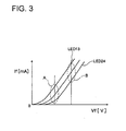
- a forward voltage (Vf) applied to the semiconductor light-emitting elements of the light source from the abnormality determination circuit can be increased, thus maintaining a current (If) of the semiconductor light-emitting elements within a fixed range. Therefore, the semiconductor light-emitting element is not affected by fluctuations in a Vf-If characteristic, and can be lit at a near constant brightness.
- the vehicular lamp described in this disclosure can help reduce the number of components and lower costs.
- an abnormality can be determined when a parallel number of disconnected semiconductor light-emitting elements exceeds a predetermined number.
- multiple semiconductor light-emitting elements can be formed as a group of semiconductor light-emitting elements connected in parallel to one another.
- a supply of current from a power source to a light source can be continued when a voltage of the power source falls to, or below, a set voltage.
- the semiconductor light-emitting element is not affected by fluctuations in a Vf-If characteristic, and can be lit at a near constant brightness.
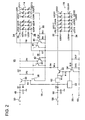
- a vehicular lamp 10 has a structure including light source blocks 12, 14, 16, abnormality determination circuits 18, 20, and a supply voltage monitoring circuit 22.
- the light source block 12 includes six light-emitting diodes (semiconductor light-emitting elements) LED1 to LED6 as a semiconductor light source forming a stop light, for example.
- the light-emitting diodes LED1 to LED6 are divided into upper and lower levels each having a set of three light-emitting diodes connected to each other in parallel (parallel number: 3), and linked in a matrix configuration so as to form a matrix with two rows and three columns.
- the light-emitting diodes LED1, LED2, are mutually connected in series
- the light-emitting diodes LED3, LED4 are mutually connected in series
- the light-emitting diode LED5 and the light-emitting diode LED6 are also mutually connected in series.
- the light-emitting diodes LED1, LED3, LED5 are mutually connected in parallel, and each anode thereof is connected to an output terminal 26.
- the light-emitting diodes LED2, LED4, LED6 are mutually connected in parallel, and each cathode thereof is connected to an output terminal 28.
- the light source block 14 includes six light-emitting diodes LED7 to LED 12 as a semiconductor light source for forming a stop lamp together with the light source block 12, for example.
- the light-emitting diodes LED7 to LED12 are divided into upper and lower levels each having a set of three light-emitting diodes connected to each other in parallel (parallel number: 3), and linked in a matrix configuration so as to form a matrix with two rows and three columns.
- the light-emitting diodes LED7, LED8, are mutually connected in series
- the light-emitting diodes LED9, LED10 are mutually connected in series
- the light-emitting diode LED 11 and the light-emitting diode LED 12 are also mutually connected in series.
- the light-emitting diodes LED7, LED9, LED11 are mutually connected in parallel, and each anode thereof is connected to an output terminal 24.
- the light-emitting diodes LED8, LED10, LED12 are mutually connected in parallel, and each cathode thereof is connected to an output terminal 30.
- the light source block 16 includes twelve light-emitting diodes LED13 to LED24 as a semiconductor light source for forming a tail lamp together with the light source blocks 12, 14 for example.
- the light-emitting diodes LED13 to LED24 are divided into upper and lower levels each having a set of six light-emitting diodes connected to each other in parallel (parallel number: 6), and linked in a matrix configuration so as to form a matrix with two rows and six columns.
- the light-emitting diodes LED13, LED14, are mutually connected in series
- the light-emitting diodes LED 15, LED 16 are mutually connected in series
- the light-emitting diodes LED17, LED18 are mutually connected in series
- the light-emitting diodes LED 19 LED20 are mutually connected in series
- the light-emitting diodes LED21, LED22, are mutually connected in series
- the light-emitting diodes LED23, LED24 are mutually connected in series.
- the light-emitting diodes LED13, LED15, LED17, LED19, LED21, LED23 are mutually connected in parallel, and each anode thereof is connected to an output terminal 32.
- the light-emitting diodes LED14, LED16, LED18, LED20, LED22, LED24 are mutually connected in parallel, and each cathode thereof is connected to an output terminal 34.
- the abnormality determination circuit 18 controls the supply of current from an on-board battery (DC power supply) to the light source blocks 12, 14.
- the abnormality determination circuit 18 determines whether there is an abnormality of the light source blocks 12, 14, and in the illustrated example, includes a PNP transistor 36; NPN transistors 38, 40, 42, 44, 46; a capacitor C1; diodes D1, D2; and resistances R1 to R11.
- a connection point of the capacitor C1 and the diode D1 is connected to an input terminal 48.
- the cathode of the diode D1 is connected to the emitter of the PNP transistor 36.
- the base of the PNP transistor 36 is connected to the collector of the NPN transistor 38 through the resistance R2, and the collector of the PNP transistor 36 is connected to the output terminals 24, 26 through the diode D2.
- the emitter of the NPN transistor 38 is grounded, and the base of the NPN transistor 38 is connected to the collectors of the NPN transistors 40, 44.
- the emitter of the NPN transistor 40 is grounded, while the base of the NPN transistor 40 is connected to the collector of the NPN transistor 42 and also connected to the output terminals 24, 26 through the resistance R4.
- the emitter of the NPN transistor 42 is grounded, while the base of the NPN transistor 42 is grounded through the resistance R5 and also connected to the output terminal 28 through the resistance R6.
- the output terminal 28 is grounded through the current-limiting resistance R7.
- the emitter of the NPN transistor 44 is grounded, while the base of the NPN transistor 44 is connected to the collector of the NPN transistor 46 and also connected to the output terminals 24, 26 through the resistance R8.
- the emitter of the NPN transistor 46 is grounded, while the base of the NPN transistor 46 is grounded through the resistance R9 and also connected to the output terminal 30 through the resistance R10.
- the output terminal 30 is grounded through the current-limiting resistance R11.
- the input terminal 48 is connected to the on-board battery (DC power supply) through a switch 50 and a main abnormality detection circuit (not shown).
- the switch 50 turns on when the brake pedal is depressed, but otherwise remains off.
- the switch 50 If the switch 50 is turned on, current from the on-board battery is provided to the input terminal 48.
- the PNP transistor 36 and the NPN transistor 38 are turned on, thus lighting each of the light-emitting diodes LED1 to LED6 of the light source block 12 and the light-emitting diodes LED7 to LED12 of the light source block 14. In other words, depression of the brake pedal lights the stop lamp.
- the current of the light source block 12 flows to the resistance R7, and a voltage drop occurs at both ends of the resistance R7.
- the voltage drop turns on the NPN transistor 42, and when this happens, the NPN transistor 40 turns off to maintain the on state of the NPN transistor 38.
- the current of the light source block 14 flows to the resistance R11, and a voltage drop occurs at both ends of the resistance R11.
- the voltage drop turns on the NPN transistor 46, and when this happens, the NPN transistor 44 turns off to maintain the on state of the NPN transistor 38.
- the abnormality determination circuit 20 controls the supply of current from an on-board battery (DC power supply) to the light source blocks 12, 14, 16.
- the abnormality determination circuit 20 includes a PNP transistor 52; an NPN transistor 54; a capacitor C2; diodes D3, D4; and resistances R12 to R17.
- a connection point of the capacitor C2 and the diode D3 is connected to an input terminal 56.
- the cathode of the diode D3 is connected to the emitter of the PNP transistor 52.
- the base of the PNP transistor 52 is connected to the collector of the NPN transistor 54 through the resistance R13, while the collector of the PNP transistor 52 is connected to the output terminals 24, 26 through the resistance R14 and the diode D4, and also connected to the output terminal 32.
- the emitter of the NPN transistor 54 is grounded, while the base of the NPN transistor 54 is grounded through the resistance R15 and also connected to the output terminal 34 through the resistance R16.
- the output terminal 34 is grounded through the current-limiting resistance R17.
- the input terminal 56 is connected to the on-board battery (DC power supply) through a switch 58 and a main abnormality detection circuit (not shown).
- the switch 58 turns on in response to an operation for lighting the tail lamp, but otherwise remains off.
- the switch 58 If the switch 58 is turned on, current from the on-board battery is provided to the input terminal 56.
- the PNP transistor 52 and the NPN transistor 54 are turned on, thus lighting each of the light-emitting diodes LED1 to LED6 of the light source block 12, the light-emitting diodes LED7 to LED12 of the light source block 14, and the light-emitting diodes LED 13 to LED24 of the light source block 16.
- the tail lamp turns on in response to an operation for lighting the tail lamp.
- a current smaller than the current used when the light source blocks 12, 14 function as a stop lamp is supplied through the resistance R14 and the diode D4 to the light-emitting diodes LED1 to LED6 of the light source block 12 and the light-emitting diodes LED7 to LED 12 of the light source block 14.
- the PNP transistor 52 and the NPN transistor 54 are turned off, thus turning off each of the light-emitting diodes LED1 to LED6 of the light source block 12, the light-emitting diodes LED7 to LED 12 of the light source block 14, and the light-emitting diodes LED13 to LED24 of the light source block 16.
- the supply voltage monitoring circuit 22 monitors the voltage (supply voltage) applied to the input terminals 48, 56. When the voltage (supply voltage) applied to the input terminals 48, 56 exceeds a set voltage, there is high impedance at the connection point between the resistance R2 and the collector of NPN transistor 38, and at the connection point between the resistance R13 and the collector of the NPN transistor 54.
- the supply voltage monitoring circuit 22 forcibly turns on the PNP transistor 36 and sets the connection point between the resistance R2 and the collector of the NPN transistor 38 at the low level.
- the supply voltage monitoring circuit 22 forcibly stops the abnormality determination circuit 18 from performing the abnormality determination, and supplies current from the on-board battery to the light source blocks 12, 14 so as to light the light source blocks 12, 14 as the stop lamp.
- the supply of current from the on-board battery to the light source blocks 12, 14 can be continued when the voltage (supply voltage) applied to the input terminal 48 is equal to or less than the set voltage.
- the supply voltage monitoring circuit 22 when the voltage (supply voltage) applied to the input terminal 58 falls to, or below, the set voltage, the supply voltage monitoring circuit 22 forcibly turns on the PNP transistor 52 using the connection point between the resistance R13 and the collector of the NPN transistor 54 as the low level. In other words, when the voltage (supply voltage) applied to the input terminal 58 is equal to or less than the set voltage, the supply voltage monitoring circuit 22 forcibly stops the abnormality determination circuit 20 from performing the abnormality determination, and supplies current from the on-board battery to the light source blocks 12, 14, 16 so as to light the light source blocks 12, 14, 16 as the tail lamp.
- the supply of current from the on-board battery to the light source blocks 12, 14, 16 can be continued when the voltage (supply voltage) applied to the input terminal 56 is equal to or less than the set voltage.
- An input terminal 60 is connected to a negative terminal of the on-board battery (DC power supply) as a ground potential for each circuit.
- turning on the switch 50 provides current from the on-board battery to the input terminal 48.
- the PNP transistor 36 and the NPN transistor 38 are then turned on, thus lighting each of the light-emitting diodes LED1 to LED6 of the light source block 12 and the light-emitting diodes LED7 to LED12 of the light source block 14.
- a disconnection of any light-emitting diode may occur among either the light-emitting diodes LED1 to LED6 of the light source block 12 or the light-emitting diodes LED7 to LED12 of the light source block 14 (e.g., the light-emitting diode LED1 on the upper level may disconnect).
- the current flowing to the light-emitting diodes LED3, LED5 is half the total current (sum current) of the light-emitting diodes LED2, LED4, and LED6.
- the light source block 12 In this case, the light source block 12 in cooperation with the light source block 14 functions as the stop lamp.
- a disconnection of any two light-emitting diodes connected in parallel may occur among either the light-emitting diodes LED1 to LED6 of the light source block 12 or the light-emitting diodes LED7 to LED12 of the light source block 14 (e.g., the light-emitting diodes LED1 and LED3 on the upper level may disconnect).
- the current flowing to the light-emitting diode LED5 is equivalent to the total current (sum current) of the light-emitting diodes LED2, LED4, and LED6.
- the parallel number of disconnected light-emitting diodes i.e., LED1, LED3 is a predetermined number of two or less (a number that satisfies the light distribution standard). Therefore, the light source block 12 in cooperation with the light source block 14 functions as the stop lamp.
- a disconnection of any three light-emitting diodes connected in parallel may occur among either the light-emitting diodes LED1 to LED6 of the light source block 12 or the light-emitting diodes LED7 to LED12 of the light source block 14 (e.g., the light-emitting diodes LED1, LED3, and LED5 on the upper level may disconnect).
- the parallel number of disconnected light-emitting diodes i.e., LED1, LED3, LED5
- the circuit is shut off and current no longer flows to the light source block 12.
- the voltage at both ends of the resistance R7 drops (to 0 V), which turns off the NPN transistor 42 and turns on the NPN transistor 40.
- the NPN transistor 40 turns on, the NPN transistor 38 and the PNP transistor 36 are turned off, which stops the supply of current to the light source blocks 12, 14. Accordingly, the light-emitting diodes LED1 to LED6 of the light source block 12 and the light-emitting diodes LED7 to LED 12 of the light source block 14 are all turned off.
- the light-emitting diodes LED1 to LED6 of the light source block 12 are in normal operation, there may be a disconnection of any two light-emitting diodes connected in parallel among the light-emitting diodes LED7 to LED12 of the light source block 14, e.g., the light-emitting diodes LED7 and LED9 on the upper level may disconnect. In this case, current flows to the light-emitting diodes LED8 and LED 10 on the lower level via the light-emitting diode LED11 on the upper level of the light source block 14.
- the NPN transistor 46 is maintained in the on state, which together with the turned-on PNP transistor 36 and the NPN transistor 38, lights the light-emitting diodes LED8, LED10, LED11, LED12.
- the parallel number of disconnected light-emitting diodes i.e., LED7, LED9 is a predetermined number of two or less (a number that satisfies the light distribution standard). Therefore, the light source block 14 in cooperation with the light source block 12 functions as the stop lamp.
- the light-emitting diodes LED1 to LED6 of the light source block 12 are in normal operation, a disconnection of any three light-emitting diodes connected in parallel may occur among the light-emitting diodes LED7 to LED12 of the light source block 14 (e.g. the light-emitting diodes LED7, LED9, and LED11 on the upper level may disconnect).
- the parallel number of disconnected light-emitting diodes i.e., LED7, LED9, LED11
- the circuit is shut off and current no longer flows to the light source block 14.
- the voltage at both ends of the resistance R11 drops, which turns off the NPN transistor 46 and turns on the NPN transistor 44.
- the NPN transistor 44 turns on, the NPN transistor 38 and the PNP transistor 36 are turned off, which stops the supply of current to the light source blocks 12, 14. Accordingly, the light-emitting diodes LED1 to LED6 of the light source block 12 and the light-emitting diodes LED7 to LED12 of the light source block 14 are all turned off.
- a main abnormality detection circuit (not shown) between the switches 50, 58 and the on-board battery (DC power supply) communicates the occurrence of an abnormality resulting from the disconnection in the light source blocks 12, 14 to a vehicle control unit (not shown).
- the switch 58 provides current from the on-board battery to the input terminal 58.
- the PNP transistor 52 and the NPN transistor 54 are then turned on, thus lighting each of the light-emitting diodes LED1 to LED6 of the light source block 12, the light-emitting diodes LED7 to LED 12 of the light source block 14, and the light-emitting diodes LED 13 to LED24 of the light source block 16.
- the light source block 16 still lights using normal light-emitting diodes even if there is a disconnection of one to five light-emitting diodes connected in parallel to one another among the light-emitting diodes LED13 to LED24 of the light source block 16.
- five light-emitting diodes LED13, LED15, LED17, LED19, LED21 which are arranged in a row and connected in parallel, may disconnect among the light-emitting diodes LED13 to LED24 of the light source block 16.
- the parallel number of disconnected light-emitting diodes i.e., LED13, LED15, LED17, LED19, LED21
- the light source block 16 in cooperation with the light source blocks 12, 14 functions as the stop lamp.
- the parallel number of disconnected light-emitting diodes i.e., LED13, LED15, LED17, LED19, LED21, LED23
- the circuit is shut off and current no longer flows to the light source block 16.
- the voltage at both ends of the resistance R17 drops (to 0 V) and the NPN transistor 54 and the PNP transistor 52 are turned off such that the supply of current to the light source blocks 12, 14, 16 is stopped. Accordingly, the light-emitting diodes LED1 to LED6 of the light source block 12, the light-emitting diodes LED7 to LED12 of the light source block 14, and the light-emitting diodes LED13 to LED24 of the light source block 16 are all turned off.
- the main abnormality detection circuit (not shown) between the switches 50, 58 and the on-board battery (DC power supply) communicates the occurrence of an abnormality resulting from the disconnection in the light source block 16 to the vehicle control unit (not shown).
- the parallel number of disconnected light-emitting diodes being three, which is more than the predetermined number of two (the number that satisfies the light distribution standard), is used as a condition. Based on this condition, it is determined that an abnormality resulting from the disconnection has occurred in either the light source block 12 or 14, and the supply of current to the light source blocks 12, 14 stopped. It is thus not necessary to provide three line breakage detection circuits each for the light source blocks 12, 14 in order to determine abnormality of the light source blocks 12, 14, which can help reduce the number of components and lower costs.
- the parallel number of disconnected light-emitting diodes LED being six, which is more than the predetermined number of five (the number that satisfies the light distribution standard), is used as a condition. Based on this condition, it is determined that an abnormality resulting from the disconnection has occurred in the light source block 16, and the supply of current to the light source blocks 12, 14, 16 stopped. It is thus not necessary to provide six line breakage detection circuits for the light source block 16 in order to determine abnormality of the light source block 16, which can help reduce the number of components and lower costs.
- the light source blocks 12, 14, 16 even if a portion of the light-emitting diodes of the light source blocks 12, 14, 16 disconnects, current is supplied to the light source blocks 12, 14 or the light source block 16 until the abnormality of the light source blocks 12, 14 or the light source block 16 is determined. Therefore, the light source blocks 12, 14 can be effectively utilized as a stop lamp, and the light source block 16 as a tail lamp.
- This embodiment provides an oscillation circuit 62 between the emitter of the PNP transistor 52 and the cathode of the diode D3 of the abnormality determination circuit 20, and applies an output signal of the oscillation circuit 62 to the emitter of the PNP transistor 52.
- Other structures of the second embodiment are identical to the first embodiment.
- the oscillation circuit 62 is configured, for example, as an oscillation circuit that generates a pulse width modulation (PWM) signal and applies the PWM signal at a constant on-duty ratio to the emitter of the PNP transistor 52.
- PWM pulse width modulation
- the first embodiment employed a configuration that supplies tens of percent of the rated current to the light-emitting diodes LED13 to LED 24 through the PNP transistor 52.
- a current If of the light-emitting diodes LED13 to LED24 exhibits large variation due to the effect of fluctuations in the Vf-If characteristic.
- the parallel number of light-emitting diodes connected in parallel to one another may be another number provided that it is two or more.
- the predetermined number pertaining to the parallel number of disconnected light-emitting diodes can be set based on the condition that the parallel number of disconnected light-emitting diodes reaching the predetermined number satisfies the light distribution standard.
- a circuit configuration is needed to ensure that, if the parallel number of the disconnected light-emitting diodes exceeds the predetermined number, current does not flow to other light-emitting diodes linked to the disconnected light-emitting diodes.
Landscapes
- Engineering & Computer Science (AREA)
- Mechanical Engineering (AREA)
- Led Devices (AREA)
- Lighting Device Outwards From Vehicle And Optical Signal (AREA)
- Circuit Arrangement For Electric Light Sources In General (AREA)
Applications Claiming Priority (1)
| Application Number | Priority Date | Filing Date | Title |
|---|---|---|---|
| JP2008252347A JP2010083235A (ja) | 2008-09-30 | 2008-09-30 | 車両用灯具 |
Publications (2)
| Publication Number | Publication Date |
|---|---|
| EP2170011A2 true EP2170011A2 (de) | 2010-03-31 |
| EP2170011A3 EP2170011A3 (de) | 2014-07-16 |
Family
ID=41449975
Family Applications (1)
| Application Number | Title | Priority Date | Filing Date |
|---|---|---|---|
| EP09011787.0A Withdrawn EP2170011A3 (de) | 2008-09-30 | 2009-09-16 | Fahrzeuglampe |
Country Status (5)
| Country | Link |
|---|---|
| US (1) | US8227994B2 (de) |
| EP (1) | EP2170011A3 (de) |
| JP (1) | JP2010083235A (de) |
| KR (1) | KR101086534B1 (de) |
| CN (1) | CN101712297B (de) |
Families Citing this family (8)
| Publication number | Priority date | Publication date | Assignee | Title |
|---|---|---|---|---|
| TWI404003B (zh) * | 2009-10-09 | 2013-08-01 | Au Optronics Corp | 發光校正方法與顯示器 |
| JP4983941B2 (ja) * | 2010-03-02 | 2012-07-25 | 株式会社デンソー | 通電制御装置 |
| CN102340910A (zh) * | 2010-07-28 | 2012-02-01 | 咸瑞科技股份有限公司 | 发光二极管控制电路 |
| US20120069559A1 (en) * | 2011-11-20 | 2012-03-22 | Foxsemicon Integrated Technology, Inc. | Lighting module |
| JP5576892B2 (ja) * | 2012-03-13 | 2014-08-20 | オムロンオートモーティブエレクトロニクス株式会社 | Led点灯および断線検出制御装置 |
| DE102013222226B3 (de) * | 2013-10-31 | 2015-04-16 | Osram Gmbh | Schaltungsanordnung zum Betreiben mindestens einer ersten und einer zweiten Kaskade von LEDs |
| JP6934331B2 (ja) * | 2017-06-15 | 2021-09-15 | 株式会社小糸製作所 | 発光駆動回路、車両用灯具 |
| KR102680494B1 (ko) * | 2019-09-30 | 2024-07-02 | 현대모비스 주식회사 | 차량의 램프 제어 장치 및 그 동작 방법 |
Citations (1)
| Publication number | Priority date | Publication date | Assignee | Title |
|---|---|---|---|---|
| JP2006248509A (ja) | 2005-02-14 | 2006-09-21 | Koito Mfg Co Ltd | 車両用灯具システム |
Family Cites Families (9)
| Publication number | Priority date | Publication date | Assignee | Title |
|---|---|---|---|---|
| US6362578B1 (en) | 1999-12-23 | 2002-03-26 | Stmicroelectronics, Inc. | LED driver circuit and method |
| JP2004009826A (ja) * | 2002-06-05 | 2004-01-15 | Koito Mfg Co Ltd | 車両用灯具装置 |
| JP2004009825A (ja) * | 2002-06-05 | 2004-01-15 | Koito Mfg Co Ltd | 車両用灯具装置 |
| JP4400880B2 (ja) * | 2004-10-05 | 2010-01-20 | 株式会社小糸製作所 | 車両用灯具の点灯制御回路 |
| JP2006222412A (ja) * | 2005-01-17 | 2006-08-24 | Citizen Electronics Co Ltd | 発光装置 |
| CN100531491C (zh) * | 2005-02-14 | 2009-08-19 | 株式会社小糸制作所 | 车辆用灯具系统 |
| KR100672258B1 (ko) | 2005-03-07 | 2007-01-22 | 아이에이치엘 주식회사 | 차량의 방향지시등 고장 감지장치 |
| US20100109537A1 (en) * | 2006-10-25 | 2010-05-06 | Panasonic Electric Works Co., Ltd. | Led lighting circuit and illuminating apparatus using the same |
| JP6030922B2 (ja) * | 2012-06-11 | 2016-11-24 | 株式会社小糸製作所 | 光源制御装置 |
-
2008
- 2008-09-30 JP JP2008252347A patent/JP2010083235A/ja active Pending
-
2009
- 2009-09-11 US US12/557,556 patent/US8227994B2/en not_active Expired - Fee Related
- 2009-09-16 EP EP09011787.0A patent/EP2170011A3/de not_active Withdrawn
- 2009-09-23 CN CN200910175865.0A patent/CN101712297B/zh not_active Expired - Fee Related
- 2009-09-28 KR KR1020090091696A patent/KR101086534B1/ko not_active Expired - Fee Related
Patent Citations (1)
| Publication number | Priority date | Publication date | Assignee | Title |
|---|---|---|---|---|
| JP2006248509A (ja) | 2005-02-14 | 2006-09-21 | Koito Mfg Co Ltd | 車両用灯具システム |
Also Published As
| Publication number | Publication date |
|---|---|
| KR101086534B1 (ko) | 2011-11-23 |
| CN101712297B (zh) | 2014-06-11 |
| JP2010083235A (ja) | 2010-04-15 |
| CN101712297A (zh) | 2010-05-26 |
| US20100079071A1 (en) | 2010-04-01 |
| US8227994B2 (en) | 2012-07-24 |
| EP2170011A3 (de) | 2014-07-16 |
| KR20100036970A (ko) | 2010-04-08 |
Similar Documents
| Publication | Publication Date | Title |
|---|---|---|
| EP2170011A2 (de) | Fahrzeuglampe | |
| JP2004009825A (ja) | 車両用灯具装置 | |
| CN102511200B (zh) | 发光二极管阵列驱动电路 | |
| US20020047593A1 (en) | Enhanced trim resolution voltage-controlled dimming led driver | |
| US20120256550A1 (en) | Led driving circuit | |
| US20060170287A1 (en) | Lighting control circuit for vehicle lighting fixture | |
| JP5576892B2 (ja) | Led点灯および断線検出制御装置 | |
| CN1503610A (zh) | 发光二极管点灯电路 | |
| JP2004356000A (ja) | Led駆動回路 | |
| CN102695336A (zh) | 一种led灯具 | |
| CN201047522Y (zh) | 一种led发光装置的电路结构 | |
| JP2009016493A (ja) | Led発光装置 | |
| CN103369762B (zh) | 基于发光二极管的照明设备的驱动方法和装置 | |
| US9307610B2 (en) | Low power bypass circuit for LED open circuit and reverse polarity protection | |
| CN111436176B (zh) | 应急标志灯与灯具管理系统 | |
| TWI569683B (zh) | A device for driving a high voltage light emitting diode string | |
| JP2010003810A (ja) | 発光ダイオード駆動回路 | |
| US9374862B2 (en) | Circuit for vehicle lamps | |
| CN114303443B (zh) | 用于在多个led通道之间分离led电流的基于发光二极管led的电流分离器以及基于多通道发光二极管led的照明设备 | |
| CN119117043B (zh) | 一种铁路led信号灯系统及铁路led信号机 | |
| CN223809931U (zh) | 一种led驱动系统 | |
| CN212381435U (zh) | 一种低成本的led限流电路 | |
| CN216960256U (zh) | 一种应用于消防应急标志灯的led恒流驱动电路 | |
| CN212573032U (zh) | Led调光控制电路及灯具 | |
| CN207652734U (zh) | 一种车用led后雾灯电路 |
Legal Events
| Date | Code | Title | Description |
|---|---|---|---|
| PUAI | Public reference made under article 153(3) epc to a published international application that has entered the european phase |
Free format text: ORIGINAL CODE: 0009012 |
|
| 17P | Request for examination filed |
Effective date: 20090916 |
|
| AK | Designated contracting states |
Kind code of ref document: A2 Designated state(s): AT BE BG CH CY CZ DE DK EE ES FI FR GB GR HR HU IE IS IT LI LT LU LV MC MK MT NL NO PL PT RO SE SI SK SM TR |
|
| AX | Request for extension of the european patent |
Extension state: AL BA RS |
|
| PUAL | Search report despatched |
Free format text: ORIGINAL CODE: 0009013 |
|
| AK | Designated contracting states |
Kind code of ref document: A3 Designated state(s): AT BE BG CH CY CZ DE DK EE ES FI FR GB GR HR HU IE IS IT LI LT LU LV MC MK MT NL NO PL PT RO SE SI SK SM TR |
|
| AX | Request for extension of the european patent |
Extension state: AL BA RS |
|
| RIC1 | Information provided on ipc code assigned before grant |
Ipc: H05B 33/08 20060101AFI20140610BHEP Ipc: B60Q 1/00 20060101ALI20140610BHEP |
|
| STAA | Information on the status of an ep patent application or granted ep patent |
Free format text: STATUS: THE APPLICATION HAS BEEN WITHDRAWN |
|
| 18W | Application withdrawn |
Effective date: 20151125 |