EP2170144B1 - Appareil de séparation de poussière d'aspirateur - Google Patents
Appareil de séparation de poussière d'aspirateur Download PDFInfo
- Publication number
- EP2170144B1 EP2170144B1 EP08766286.2A EP08766286A EP2170144B1 EP 2170144 B1 EP2170144 B1 EP 2170144B1 EP 08766286 A EP08766286 A EP 08766286A EP 2170144 B1 EP2170144 B1 EP 2170144B1
- Authority
- EP
- European Patent Office
- Prior art keywords
- passage
- air
- dust
- dust separation
- vacuum cleaner
- Prior art date
- Legal status (The legal status is an assumption and is not a legal conclusion. Google has not performed a legal analysis and makes no representation as to the accuracy of the status listed.)
- Not-in-force
Links
- 239000000428 dust Substances 0.000 title claims description 176
- 238000000926 separation method Methods 0.000 title claims description 85
- 230000003247 decreasing effect Effects 0.000 claims description 2
- 238000007599 discharging Methods 0.000 description 10
- JTJMJGYZQZDUJJ-UHFFFAOYSA-N phencyclidine Chemical class C1CCCCN1C1(C=2C=CC=CC=2)CCCCC1 JTJMJGYZQZDUJJ-UHFFFAOYSA-N 0.000 description 7
- 239000000356 contaminant Substances 0.000 description 4
- 238000010276 construction Methods 0.000 description 3
- 238000005192 partition Methods 0.000 description 3
- 238000003825 pressing Methods 0.000 description 3
- 238000011144 upstream manufacturing Methods 0.000 description 2
- 230000006835 compression Effects 0.000 description 1
- 238000007906 compression Methods 0.000 description 1
- 230000000994 depressogenic effect Effects 0.000 description 1
- 230000000694 effects Effects 0.000 description 1
- 239000012530 fluid Substances 0.000 description 1
- 238000009434 installation Methods 0.000 description 1
- 238000000034 method Methods 0.000 description 1
- 239000002245 particle Substances 0.000 description 1
- 238000007789 sealing Methods 0.000 description 1
Images







Classifications
-
- A—HUMAN NECESSITIES
- A47—FURNITURE; DOMESTIC ARTICLES OR APPLIANCES; COFFEE MILLS; SPICE MILLS; SUCTION CLEANERS IN GENERAL
- A47L—DOMESTIC WASHING OR CLEANING; SUCTION CLEANERS IN GENERAL
- A47L9/00—Details or accessories of suction cleaners, e.g. mechanical means for controlling the suction or for effecting pulsating action; Storing devices specially adapted to suction cleaners or parts thereof; Carrying-vehicles specially adapted for suction cleaners
- A47L9/10—Filters; Dust separators; Dust removal; Automatic exchange of filters
- A47L9/16—Arrangement or disposition of cyclones or other devices with centrifugal action
- A47L9/1616—Multiple arrangement thereof
- A47L9/1625—Multiple arrangement thereof for series flow
-
- A—HUMAN NECESSITIES
- A47—FURNITURE; DOMESTIC ARTICLES OR APPLIANCES; COFFEE MILLS; SPICE MILLS; SUCTION CLEANERS IN GENERAL
- A47L—DOMESTIC WASHING OR CLEANING; SUCTION CLEANERS IN GENERAL
- A47L9/00—Details or accessories of suction cleaners, e.g. mechanical means for controlling the suction or for effecting pulsating action; Storing devices specially adapted to suction cleaners or parts thereof; Carrying-vehicles specially adapted for suction cleaners
- A47L9/10—Filters; Dust separators; Dust removal; Automatic exchange of filters
- A47L9/16—Arrangement or disposition of cyclones or other devices with centrifugal action
- A47L9/1616—Multiple arrangement thereof
- A47L9/1641—Multiple arrangement thereof for parallel flow
-
- A—HUMAN NECESSITIES
- A47—FURNITURE; DOMESTIC ARTICLES OR APPLIANCES; COFFEE MILLS; SPICE MILLS; SUCTION CLEANERS IN GENERAL
- A47L—DOMESTIC WASHING OR CLEANING; SUCTION CLEANERS IN GENERAL
- A47L9/00—Details or accessories of suction cleaners, e.g. mechanical means for controlling the suction or for effecting pulsating action; Storing devices specially adapted to suction cleaners or parts thereof; Carrying-vehicles specially adapted for suction cleaners
- A47L9/10—Filters; Dust separators; Dust removal; Automatic exchange of filters
- A47L9/16—Arrangement or disposition of cyclones or other devices with centrifugal action
- A47L9/165—Construction of inlets
Definitions
- This document relates to a dust separation apparatus of a vacuum cleaner.
- a vacuum cleaner is an apparatus that sucks air containing dusts using vacuum pressure generated by a suction motor mounted in a main body and filters off the dusts in the main body.
- air sucked from a suction nozzle should be freely flowed into a cleaner main body.
- the air flow is an important criterion in the performance of the vacuum cleaner.
- GB 2 360 719 A relates to an apparatus for separating particles from a fluid flow comprising an upstream cyclonic separator and a plurality of downstream cyclonic separators 26 arranged in parallel with one another. Each of the downstream cyclonic separators projects, at least in part, into the interior of the upstream cyclonic separator.
- EP 1 438 918 A1 relates to a vacuum cleaner comprising various dust containers without connection among them and provided with one or more covers which in their interior design perform the function of collector, there existing an air inlet via at least one of the containers, which are joined forming the aforementioned air outlet collector in the interior of the cover or covers (2) and in a single air outlet towards the motor.
- EP 1 776 910 A2 relates to a multi-cyclone dust collector for a vacuum cleaner.
- the multi-cyclone dust collector includes a first cyclone forcing contaminants-laden air that is drawn-in at a lower portion of the first cyclone to form an upwardly whirling air current so as to centrifugally separate contaminants therefrom air, a first contaminants chamber wrapping around a first part of the first cyclone and collecting contaminants discharged from the first cyclone, and a second cyclone unit wrapping around a second part of the first cyclone and having a plurality of second cyclones, each of the plurality of second cyclones drawing-in semi-clean air discharged from the first cyclone at an upper portion of each of the plurality of second cyclones so as to centrifugally separate fine contaminants from the semi-clean air.
- EP 1 779 761 A2 relates to a multi-cyclone dust separating apparatus having a main cyclone comprising one or more cyclones, a sub cyclone comprising one or more cyclones, and being arranged around a part of the main cyclone in parallel relation, and a dust collecting casing provided to enclose the main and the sub cyclones, and collects dust as the dust is separated from the air in the main and the sub cyclones.
- An object of the present embodiment is to propose a dust separation apparatus of a vacuum cleaner, which improves the dust separation performance.
- Another object of the present embodiment is to propose a dust separation apparatus of a vacuum cleaner, which allows air to be freely flowed into a dust separation unit for separating dusts.
- a dust separation apparatus of a vacuum cleaner including: a dust separation unit; and a distribution unit which distributes air and dust to the dust separation unit, wherein the distribution unit includes a body forming an external appearance, an introducing hole for introducing the air and dust to the body, a plurality of branch passages for distributing the air introduced into the body to the dust separation unit, and a main passage for connecting the introducing hole with the respective branch passage, and wherein a passage cross-sectional area of the main passage at the branch passage is greater than a passage cross-sectional area of the main passage at the introducing hole.
- a dust separation apparatus of a vacuum cleaner including: a dust separation unit; and a distribution unit which distributes air and dust to the dust separation unit, wherein the distribution unit includes an introducing hole for introducing the air and dust to the body, and a first passage and a second passage through which the air introduced into the body is flowed, and a first distributing pipe communicating with the first passage and a second distributing pipe communicating with the second passage, and wherein the volume of the first passage is greater than the volume of the second passage.
- a dust separation apparatus of a vacuum cleaner including: a dust separation unit; and a distribution unit which distributes air and dust to the dust separation unit, wherein the distribution unit includes an introducing hole for introducing the air and dust, a plurality of branch passages to which the air is distributed through the introducing hole, and an intermediate passage which is communicated with the branch passage and to which at least some of the air introduced from the introducing hole is moved, and wherein a vertical width of the plurality of branch passages is greater than a vertical width of the intermediate passage on the basis of the air flow.
- a dust separation apparatus of a vacuum cleaner including: a distribution unit, in which a main passage and a plurality of branch passages branched from the main passage are formed; a cover element for opening/closing the distribution unit; and a dust separation unit which separates the dust from the air introduced from the distribution unit.
- the dust separating performance may be preferably increased, since the passage cross-sectional area is increased and the passage loss is reduced by generating a plurality of cyclone flows in the cyclone, as a plurality of suction parts are formed at a dust separation unit.
- the bulky dust is preferably prevented from being caught in the distribution unit and the air flow is freely accomplished, since the bulky dust of dusts introduced into the distribution unit may be moved to one branch passage of a pluraity of branch passages.
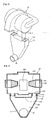
- FIGURE 1 shows a dust separation apparatus of a vacuum cleaner according to a first embodiment in a perspective view
- FIGURE 2 shows the dust separation apparatus in an exploded perspective view.
- the dust separation apparatus 1 of the vacuum cleaner includes a dust separation unit 20 which separates dust from air, a distribution unit 10 which allows air to be distributed to the dust separation unit 20, and a suction guide 30 which allows air to be moved into the distribution unit 10.
- the suction guide 30 is a part which guides air sucked from a suction nozzle (not illustrated) to the distribution unit 10, and it may be provided in a cleaner main body which is not illustrated.
- the dust separation unit 20 separates dust from air introduced from the distribution unit 10. And, a plurality of air-suction parts 210 are formed in the dust separation unit 20.
- the distribution unit 10 is disposed between the suction guide 30 and the dust separation unit 20, and it distributes air introduced from the suction guide 30 to each of the air-suction parts 210.
- the suction guide 30 and the distribution unit 10 may be integrally formed or connected to each other. In case the suction guide 30 and the distribution unit 10 are connected to each other, an introducing hole (not illustrated) through which air and dust of the suction guide 30 are introduced is formed at the distribution unit 10.
- an inlet of the suction guide 30 serves as the introducing hole of the distribution unit 10.
- the distribution unit 10 includes a plurality of distributing pipes 110 for distributing air. And, each of the distributing pipes 110 is communicated with each of the air-suction parts 210.
- FIGURE 3 shows a cross section taken along A-A in Fig. 1 in a cross-sectional view
- FIGURE 4 shows air flow in a distribution unit according to the first embodiment of the present invention in a cross-sectional view.
- the distribution unit 10 is disposed below the dust separation unit 20.
- the distribution unit 10 includes a body 100 in which a main passage 120 is formed, a plurality of distributing pipes 110 which are extended from the body 100, and a distribution guide 130 which is formed between the distributing pipes 110 to guide air to each of the distributing pipes 110. And, the distribution guide 130 makes the distributing pipes 110 spaced apart from each other. And, the body 100 is laterally symmetrically formed so that air is uniformly distributed to each of the distributing pipes 110.
- a branch passage 140 is respectively formed at each of the distributing pipes 110, and the branch passage 140 is communicated with the main passage 120.
- the respective distributing pipe 110 is connected to an exterior of the respective air-suction part 210. That is, each of the air-suction parts 210 is inserted into each of the distributing pipes 110. On the other hand, the respective distributing pipe 110 may be inserted into the respective air-suction part 210.
- a sealing element 112 for preventing the leakage of air may be provided at a connection region between the air-suction part 210 and the distributing pipe 110.
- a passage cross-sectional area of the main passage 120 is increased from the suction guide 30 to the distributing pipe 110 so that air introduced into the main passage 120 can be freely distributed to each of the distributing pipes 110.
- Air containing dust, which is sucked from the outside, is introduced into the main passage 120 of the distribution unit 10 via the suction guide 30. And, the air introduced into the main passage 120 is upwardly moved. Some of the air is directly moved into the respective distributing pipe 110 while the air is upwardly moved. And, other of the air is moved into respective distributing pipe 110 as it is guided by the distribution guide 130.
- the air distributed into the respective distributing pipe 110 is introduced into the dust separation unit 20 via the respective air-suction part 210.
- the air introduced into the dust separation unit 20 is circulated along an inner circumferential surface of the dust separation unit 20, and in this process, air and dust are separated from each other as different centrifugal forces are applied due to the difference in weight. That is, the dust separation unit 20 separates dust from air containing dust by the cyclone principle.
- the separated dust is discharged from the dust separation unit 20 through a dust discharging part 230 formed at the center of the dust separation unit 20. And, the dust discharged from the dust separation unit 20 is collected in a dust collecting container which is not illustrated.
- the air separated from dust is filtered off as it passes through filter elements 240 installed at both sides of the dust separation unit 20, and it passes through air discharging holes 222 formed at both sides of the dust separation unit 20.
- the dust discharging part 230 is disposed between the plurality of air-suction parts 210.
- the air passed through the air discharging hole 222 is discharged from the dust separation unit 20, as it is flowed along a air discharging part 220 formed at outer both sides of the dust separation unit 20.
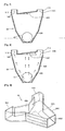
- FIGURE 5 shows a distribution unit according to a second embodiment in a cross-sectional view
- FIGURE 6 shows air flow in the distribution unit according to the second embodiment in a cross-sectional view.
- the present embodiment is almost the same as the first embodiment, except for the shape of the distribution unit. Accordingly, the characteristic parts of the present embodiment will be explained.
- a distribution unit 40 includes a body 400 which is laterally symmetrically formed.
- the distance L1 from a side adjacent to the suction guide 30 to a side adjacent to a first branch passage 440 of a first distributing pipe 410 is shorter than the distance L2 from a side adjacent to the suction guide 30 to a side adjacent to a second branch passage 442 of a second distributing pipe 412. That is, the body 400 is formed in a shape that is eccentric to the first distributing pipe 410.
- one side of the body 400 is downwardly extended from the first distributing pipe 410, and the other side of the body 400 is inclined from the second distributing pipe 412 to the suction guide 30. Accordingly, a main passage 420, through which air is flowed, is increased in its width toward the second distributing pipe 412. And, the suction guide 30 is disposed adjacent to the first distributing pipe 410.
- the air sucked from the outside is introduced into the main passage 420 via the suction guide 30.
- the air introduced into the main passage 420 is not uniformly distributed into the respective distributing pipe 410, 412, but large amount of air is unevenly distributed to the first distributing pipe 410. And, the relatively small amount of air is distributed to the second distributing pipe 412.
- the configuration of the distribution unit 40 is eccentric to the first distributing pipe 410, bulky dusts are distributed to the first distributing pipe 410 and micro dusts are distributed to the second distributing pipe 412. Therefore, the air flow in the distribution unit 40 is freely moved, since the bulky dusts are not caught by the distribution guide 430.
- FIGURE 7 shows a distribution unit according to a third embodiment in a cross-sectional view
- FIGURE 8 shows air flow in the distribution unit according to the third embodiment in a cross-sectional view.
- the present embodiment is almost the same as the first embodiment, except for the shape of the distribution unit. Accordingly, the characteristic parts of the present embodiment will be explained.
- the distribution unit 50 includes a body 500 in which a main passage 520 is formed, a pair of distributing pipes 510, 512 to which air in the main passage 520 is distributed, and a distribution guide 530 which is inclinedly formed to distribute the air in the main passage 520 to the respective distributing pipe 510, 512.
- the body 500 is laterally symmetrically formed from the suction guide 30 only to an inlet of a second distributing pipe 512.
- the distribution guide 530 is upwardly inclined from the second distributing pipe 512 to a first distributing pipe 510.
- the distribution guide 530 is formed to be inclined at a predetermined angle ⁇ with respect to a horizontal line. Accordingly, large amount of air in the main passage 520 is distributed to the first distributing pipe 510 by the distribution guide 530.
- the angle ⁇ is preferably more than 10 degrees in order to accomplish the eccentric distribution of flow.
- the air sucked from the outside is introduced into the main passage 520 via the suction guide 30.
- some of the air introduced into the main passage 520 is directly moved to a first and second distributing pipes 510, 512. And, the remainder of air is moved toward the distribution guide 530.
- the air moved toward the distribution guide 530 is distributed to the first distributing pipe 510 by the distribution guide 530. Accordingly, bulky dusts are prevented from being caught by the distribution guide 530, since the bulky dusts are moved toward the first distributing pipe 510 by the distribution guide 530.
- FIGURE 9 shows a distribution unit according to a fourth embodiment in a perspective view
- FIGURE 10 shows the distribution unit according to the fourth embodiment in a cross-sectional view.
- the present embodiment is almost the same as the first embodiment, except for the shape of the distribution unit. Accordingly, the characteristic parts of the present embodiment will be explained.
- the distribution unit 60 includes a body 600 in which a main passage 610 is formed, a pair of distributing pipes 620, 622 which are extended from the body 600 and to which the air in the main passage 610 is distributed, and a guide element 640 which guides bulky dusts to any one of the distributing pipes.
- a suction port 602 for sucking air is formed at the body 600.
- a distribution guide 630 which distributes the air in the main passage 610 to the respective distributing pipe 620,622, is formed at the body 600.
- a boundary part 631 which is a boundary where the sucked air is distributed to the distributing pipes 620, 622, is formed at the center of the distribution guide 630. And, the body 600 is laterally symmetrically formed with respect to the boundary part 631.
- the width of the body 600 is increased from the suction port 602 to the respective distributing pipe 620, 622. That is, the passage cross-sectional area of the body 600 is increased from the suction port 602 to the respective distributing pipe 620, 622.
- the guide element 640 is installed at only one side of the main passage 610. That is, the guide element 640 is disposed adjacent to the second distributing pipe 622 with respect to the boundary part 631. And, a plurality of guide elements 640 may be installed at intervals in a direction perpedicular to the air flow direction in the main passage 610. The arranged direction of the guide elements 640 will be understood with respect to Fig. 9 .
- the distance between the guide elements may be determined by considering the size of bulky dusts, such as a tissue.
- the bulky dusts are moved toward a first branch passage 624 of the first distributing pipe 620, as the movement thereof is guided by a first end 641 of the guide element 640.
- micro dusts are moved toward a second branch passage 626 of the first distributing pipe 622 by passing though a space between the guide elements 640.
- the air flow in the distribution unit 60 tends to be eccentric to the first distributing pipe 620, because of the installation of the guide element 640. This is because the guide element 640 serves as a resistance.
- the air flow may substantially uniformly distributed.
- b will be at least twice as long as a.
- a second end 642 of the guie element 640 is spaced part from the boundary part 631 at a predetermined distance c.
- the predetermined distance c is preferably greater than 3mm so that dusts such as a hair or a thread cannot be caught by the boundary part 631 or the guide element 640.
- FIGURE 11 shows a distribution unit according to a fifth embodiment in a cross-sectional view.
- the present embodiment is the same as the fourth embodiment, except for the shape of the distribution unit. Accordingly, the characteristic parts of the present embodiment will be explained and the descriptions corresponding to the fourth embodiment will be omitted.
- a circular cone shaped guide element 650 is provided in the distribution unit 60 of the present embodiment.
- the guide element 650 is installed at only one side of the main passage 610. That is, the guide element 650 is disposed adjacent to the second distributing pipe 622 with respect to the boundary part 631.
- the guide element 650 is extended from one side of the body 600 toward the boundary part 631. An end of the guide element 650 is spaced apart from the boundary part 631 by a distance of "c.” Further, a plurality of guide elements 650 may be installed at intervals in a direction perpedicular to the air flow direction in the main passage 620.
- FIGURE 12 shows a distribution unit according to a sixth embodiment in a cross-sectional view.
- the present embodiment is the same as the first embodiment, except for the shape of the distribution unit. Accordingly, the characteristic parts of the present embodiment will be explained.
- the distribution unit 65 includes a body 650 having a laterally asymmetric shape.
- the body 650 includes a suction port 652 from which air is sucked, a main passage 660 through which the sucked air is flowed, a pair of distributing pipes 670, 672 where the air in the main passage 660 is distributed, and a distribution guide 680 which is disposed between the pair of distributing pipes 670, 672 to guide the air flow. And, a branch passage 674, 676 is formed at each of the distributing pipes 670, 672, respectively.
- a guide element 690 which guides bulky dusts to be moved to one distributing pipe of the pair of distributing pipes 670, 672, is formed at the main passage 620.
- the guide element 690 is formed to be adjacent to a second distributing pipe 672 with respect to a boundary part 681 of the distribution guide 680.
- the guide element 690 is connected to the distribution guide 680. Accordingly, the bulky dusts are moved toward the first distributing pipe 670 by the guide element 690.
- FIGURE 13 shows a distribution unit according to a seventh embodiment in a cross-sectional view.
- the present embodiment is the same as the sixth embodiment, except for the shape of the guide element. Accordingly, the characteristic parts of the present embodiment will be explained and the descriptions corresponding to the sixth embodiment will be omitted.
- the guide element 692 according to the present embodiment is formed to be adjacent to the second distributing pipe 672 with respect to the boundary part 681 of the distribution guide 680.
- an end of the guide element 692 is spaced apart from the boundary part 681 by a predetermined distance of c, and the distance c is preferably greater than 3mm so that dusts such as a hair or a thread cannot be caught by the boundary part 681 or an end of the guide element 692.
- Fig. 14 shows a distribution unit according to a eighth embodiment in a cross-sectional view.
- the present embodiment is the same as the sixth embodiment, except for the shape and construction of the guide element. Accordingly, the characteristic parts of the present embodiment will be explained and the descriptions corresponding to the sixth embodiment will be omitted.
- a plurality of guide elements 693 are provided in the distribution unit 65. And, the guide elements 693 are arranged from the boundary part 681 of the distribution guide 680 to the suction part 652 at a predetermined interval.
- the distance c from the guide element 693 adjacent to the boundary part 681 to the boundary part 681 is preferably greater than 3mm so that dusts such as a hair or a thread cannot be caught by the boundary part 681 or an end of the guide element 693.
- FIGURE 15 shows a distribution unit according to a ninth embodiment in a perspective view
- FIGURE 16 shows the distribution unit according to the ninth embodiment in a front view
- FIGURE 17 shows the distribution unit according to the ninth embodiment in a cross-sectional view.
- the present embodiment is the same as the first embodiment, except for the shape of the distribution unit. Accordingly, the characteristic parts of the present embodiment will be explained and the descriptions corresponding to the first embodiment will be omitted.
- the distribution unit 85 includes a body 850 which is formed to be laterally asymmetrically shaped.
- the body 850 includes a first distributing pipe 861 and a second distributing pipe 862 which distribute the air sucked into the body 850 to the dust separation unit 20, a first passage 852 and a second passage 854 which guide the air introduced from the suction guide 30 to the respective distributing pipe 861, 862, and a distribution guide 870 which is formed between the distributing pipes 861, 862 in order to guide the air to be distributed to the respective distributing pipe 861, 862.
- the body 850 includes a protrusion 880 which is formed as some of the body is outwardly protruded, and the first passage 852 is defined at a region where the protrusion 880 is formed. And, the second passage 854 is defined at the other side with respect to a guide 881 of the protrusion 880.
- the shape of the protrusion 880 will be understood with reference to Fig. 15 , and the discrimination between the first passage 852 and the second passage 854 will be understood with reference to Fig. 17 .
- the volume of the first passage 852 is different from that of the first passage 852, because of the shape of the body 850.
- the maximum width of the first passage 852 is equal to b. Further, the width of the the first passage 852 at a location of the maximum width of the first passage 852 is decreased toward the first distributing pipe 861 and the suction guide 30. And, the width of the second passage 862 is constant and equal to a.
- the volume of the first passage 852 is greater than that of the second passage 862, because of c which is the difference between the maximum width b of the first passage and the maximum width a of the second passahe 854.
- the bulky dusts introduced into the distribution unit via the suction guide 30 are moved toward the first passage 852, and therefore they are introduced into the first distributing pipe 861. Accordingly, the bulky dusts may be prevented from being caught in the distribution unit 85.
- small dusts such as a micro dust are distributed to the first passage 852 and the second passage 854, respectively.
- FIGURE 18 shows a distribution unit according to a tenth embodiment in a perspective view
- FIGURE 19 shows the distribution unit in a horizontal cross-sectional view
- FIGURE 20 shows the distribution unit in a vertical cross-sectional view.
- the present embodiment is the same as the first embodiment, except for the shape and construction of the distribution unit. Accordingly, the characteristic parts of the present embodiment will be explained.
- the distribution unit 90 includes a body 900 which is formed to be laterally symmetrically shaped.
- the body 900 includes a first branch passage 911, an intermediate passage 913 and a second branch passage 912 through which the air introduced into the body 900 is flowed, a first distributing pipe 921 and a second distributing pipe 922 which guide the air in the respective branch passage to the air-suction part (see reference numeral 210 in Fig. 1 ), and a distribution guide 930 which guides the air in intermediate passage 913 to the respective distributing pipe 921, 922.
- the body 900 is formed to be increased in its width from a side adjacent to the suction guide 30 to a side adjacent to the respective distributing pipe 921, 922.
- the intermediate passage 913 is formed between the first branch passage 911 and the second branch passage 912, and it is communicated with the respective branch passage 911, 912.
- the passage cross-sectional area of the intermediate passage 913 is increased as it is spaced apart from the suction guide 30.
- first branch passage 911 and the second branch passage 912 are formed to have the same passage cross-sectional area.
- a vertical width of the respective branch passage 911, 912 is formed to be greater than a vertical width of the intermediate passage 913. That is, the thickness of the respective branch passage 911, 912 of the body 900 is formed to be greater than the thickness of the intermediate passage 913.
- upper and lower surfaces of the body 900 are depressed to a predetermined depth in order to form the intermediate passage 913.
- the air and the micro dust which are introduced into the body 900 via the suction guide 30, flow through the respective branch passage 911, 912 and the intermediate passage 913.
- the bulky dusts are flowed through any one of the branch passages 911, 912.
- the vertical width of the intermediate passage 913 is formed to be less than the vertical width of the first branch passage 911 and the second branch passage 912, the bulky dusts may be distributed to the first branch passage 911 or the second branch passage 912 without moving into the intermediate passage 913.
- FIGURE 21 shows a distribution unit according to an eleventh embodiment in a cross-sectional view.
- the present embodiment is the same as the tenth embodiment, except for the inner construction of the distribution unit. Accordingly, the characteristic parts of the present embodiment will be explained.
- a guide rib 914 which guides bulky dusts of the introduced dusts to be distributed to the respective branch passage 911, 912, is formed in the body 900. And, the intermediate passage 913 is defined between the guide rib 914 and the distribution guide 930. Therefore, the bulky dusts are preferably prevented from being caught in the distribution unit 90, since the dust sucked from the suction guide into the body is introduced into the respective distributing pipe 921, 922 after the dust is distributed to the respective branch passage 911, 912 by the guide rib 914.
- FIGURE 22 shows a dust separation apparatus according to a twelfth embodiment in a cross-sectional view.
- the dust separation apparatus 1000 includes a dust separation unit 1020 which separates dust from the sucked air, a dust collecting container 1100 in which the dust separated from the dust separation unit 1020 is collected, and a suction guide 1030 which guides the movement of the air containing dust to the dust collecting container 1100.
- the suction guide 1030 guides the air sucked from a suction nozzle (not illustrated) to the dust collecting container 1100. And, the air introduced into the dust collecting container 1100 is guided to the dust separation unit 1020.
- the dust separation unit 1020 includes a plurality of suction parts 1022 and a dust discharging part 1024. Since the dust separation unit 1020 according to the present embodiment is the same as that of the first embodiment, the detailed explanation thereof will be omitted.
- FIGURE 23 shows a dust collecting container according to the twelfth embodiment in a perspective view
- FIGURE 24 shows a cross section taken along C-C in Fig. 23 in a cross-sectional view
- FIGURE 25 shows a cross section taken along D-D in Fig. 23 in a cross-sectional view.
- the dust collecting container 1100 includes a dust collecting body 1110, and a cover element 1180 which is connected to an upper part of the dust collecting body 1110.
- the dust collecting body 1110 includes a first wall 1111 forming an overall external appearance, and a second wall 1112 dividing an inner space of the first wall 1111 into 2 spaces.
- a dust storage part 1114 in which the dust separated from the dust separation unit 1020 is stored, is formed at one side (left side as seen in Fig. 24 ) with respect to the second wall 1112, and a distribution unit 1150, which divides the air introduced into the dust collecting body 1110, is formed at the other side (right side as seen in Fig. 24 ). That is, the distribution unit 1150 according to the present embodiment is integrally formed with the dust collecting container 1100.
- the pressing element includes a fixed element 1130 fixed on an inner circumferential surface of the dust storage part 1114, and a rotating element 1120 which is rotatably provided at the dust storage part 1114.
- the fixed element 1130 is upwardly extended from a bottom surface of the dust storage part 1114 to a predetermined height. And, a through hole 1134, through which a rotating shaft 1122 of the rotating element 1120 is passed, is formed at the second wall 1112. And, a guide rib 1132 for guiding the rotation of the rotating shaft 1122 is protruded and formed at the second wall 1112. And, the rotating shaft 1122 is tightly connected to the guide rib 1132 when the rotating shaft 1122 passes through the through hole 1134.
- some of the rotating shaft 1122 is disposed in the distribution unit 1150 by passing through the through hole 1134 and is connected with a shaft 1142 of a driven gear 1140 perforating the first wall 1111 forming the distribution unit 1150. That is, a through hole 1136 for passing the shaft 1142 of the driven gear 1140 is formed at the first wall 1111 forming the distribution unit 1150.
- the driven gear 1140 is mated with the drive gear when the dust collecting container 1100 is mounted on the cleaner main body.
- the distribution unit 1150 is defined by some of the first wall 1111 and the second wall 1112.
- the distribution unit 1150 includes a main passage 1162 into which the air discharged from the suction guide 1030 is introduced, a pair of branch passages 1163, 1164 through which the air in the main passage 1162 is divided and flowed.
- the pair of branch passages are formed, but the number of the branch passage is not restricted thereto. However, it may be formed in a number equal to the number of the suction part 1022 of the dust separation unit 1020.
- the distribution unit 1150 includes an air introducing hole 1153 which allows air to be introduced into the main passage 1162.
- a partition 1152 by which the branch passages 1163, 1164 are divided, is formed at the distribution unit 1150. And, the partition 1152 guides the air in the main passage 1162 to be distributed to the respective branch passage 1163, 1164.
- the partition 1152 is formed in the shape of a letter "U,” and is integrally formed with the second wall 1112.
- an auxiliary separation unit 1170 which separates bulky dusts such as a tissue from the air as some of the auxiliary separation unit is inserted into the distribution unit 1150, is connected to the distribution unit 1150.
- the auxiliary separation unit 1170 includes a dust separating part 1173 which separates bulky dusts such as a tissue from the air introduced into the main passage 1162.
- a dust separating part 1173 which separates bulky dusts such as a tissue from the air introduced into the main passage 1162.
- the auxiliary separation unit 1170 includes a cover 1171 which covers the opening 1154. And, one side of the cover 1171 is rotatably connected to the distribution unit 1150 by a hinge 1172, and the other side is detachably connected to the distribution unit 1150 by a fastening hook 1178.
- the dust separating part 1173 is drawn out of the distribution unit 1150 when the opening 1154 is opened by rotating the cover 1171, and the cover 1171 is disposed at the main passage 1162 when closing the opening 1154.
- dusts caught by the dust separating part 1173 may be easily removed by drawing the dust separating part 1173 out of the distribution unit 1150.
- the inside of the distribution unit 1150 may be easily cleaned after the cover is rotated.
- the dust separating part 1173 is spaced apart from the first and second walls 1111, 1112 while it is disposed on the main passage 1162.
- the dust separating part 1173 includes a pair of guides 1174 spaced apart at a specific interval, a connecting part 1175 which connects an end of the guide 1174 and is disposed adjacent to the second wall 1112, and a locking element 1176 which connects upper parts of the pair of the guide 1174.
- the horizontal width of the locking element 1176 is formed to be smaller than the horizontal width of the guide 1174. And, the locking element 1176 is spaced apart from the connecting part 1175. Accordingly, a space 1177 is formed between the locking element 1176 and the connecting part 1175.
- a plurality of through holes 1175a, through which air can be passed, are formed at an upper part of the connecting part 1175. Therefore, the upper part of the connecting part 1175 is formed in an unevenness shape.
- the cover element 1180 is connected to an upper part of the dust collecting body 1100. And, the cover element 1180 simultaneously closes the dust storage part 1114 and the distribution unit 1150 in a state where the cover element 180 is connected to the upper part of the dust collecting body 1100.
- a dust introducing hole 1182 which allows the air flowing along the dust discharging part 1024 to be introduced into the dust storage part 1114, is formed at the cover element 1180.
- an air discharging hole 1184, 1185 which allows the air in the respective branch passage 1163, 1164 to be discharged from the distribution unit 1150, is formed at the cover element 1180.
- the air containing dust is moved along the suction guide 1030. And, the air flowing along the suction guide 1030 is introduced into the main passage 1162 of the distribution unit 1150 via the air introducing hole 1153. And, the air containing dust, which is introduced into the main passage 1162, is divided and introduced into the respective branch passage 1163, 1164.
- the air containing dust in the main passage 1162 is divided into the respective branch passage 1163, 1164, the bulky dust such as a tissue is caught by the locking element 1176.
- the air introduced into the respective branch passage 1163, 1164 is moved to the suction part 1022 of the dust separation unit 1020 via the air discharging hole 1184, 1185.
- the air introduced into the dust separation unit 1020 contains the micro dust such as a hair.
- the dust separated from the dust separation unit 1020 is introduced into the dust storage part 1114 of the dust collecting container 1100 via the dust discharging part 1024 and the dust introducing hole 1182.
- the bulky dust is not introduced into the dust separation unit 1020, as the bulky dust such as a tissue is caught in the dust separating part 1173 provided at the distribution unit 1150.
- FIGURE 26 shows an aspect that an auxiliary separation unit is drawn out of a dust collecting container according to the twelfth embodiment in a perspective view.
- the auxiliary separation unit is pulled from the lower side in order to remove dust caught in the lacking element 1176. Then, the auxiliary separation unit is rotated around the hinge 1172, and therefore the dust separating part 1173 where the lacking element 1176 is formed is drawn out of the distribution unit 1150.
- the bulky dust such as a tissue is drawn together with the dust separating part 1173 while being caught by the lacking element 1176.
Landscapes
- Engineering & Computer Science (AREA)
- Mechanical Engineering (AREA)
- Filters For Electric Vacuum Cleaners (AREA)
- Filtering Of Dispersed Particles In Gases (AREA)
Claims (15)
- Appareil de séparation de poussière d'un aspirateur, comprenant :une unité de séparation de poussière (20) ; etune unité de distribution (40) qui distribue de l'air et de la poussière à l'unité de séparation de poussière,dans lequel l'unité de distribution inclutun corps (100) formant une apparence externe de celui-ci et présentant un trou d'introduction pour l'introduction de l'air et de la poussière dans le corps,une pluralité de tuyaux de distribution (110) pour la distribution de l'air introduit dans le corps à l'unité de séparation de poussière etdans lequel une section transversale du corps au niveau de la pluralité de tuyaux d'embranchement est supérieure à une section transversale du corps au niveau du trou d'introduction,caractérisé en ce quel'unité de séparation de poussière inclut une pluralité de parties d'aspiration d'air (210) etchacun de la pluralité de tuyaux de distribution (110) est en communication avec chacune des parties d'aspiration d'air (210).
- Appareil de séparation de poussière de l'aspirateur selon la revendication 1, dans lequel le corps comprend en outre un passage principal (120) reliant le trou d'introduction au tuyau de distribution respectif.
- Appareil de séparation de poussière de l'aspirateur selon la revendication 2, dans lequel le passage principal est formé pour présenter une section transversale croissante du trou d'introduction au tuyau de distribution.
- Appareil de séparation de poussière de l'aspirateur selon la revendication 2, dans lequel le passage principal est doté d'au moins un élément de guidage qui guide le déplacement d'une partie d'air et de poussière introduits dans le passage principal vers un tuyau de distribution de la pluralité de tuyaux de distribution.
- Appareil de séparation de poussière de l'aspirateur selon la revendication 4, dans lequel l'élément de guidage est prévu en une pluralité d'exemplaires, et dans lequel la pluralité d'éléments de guidage est espacée dans une direction perpendiculaire à la direction de flux de l'air.
- Appareil de séparation de poussière de l'aspirateur selon la revendication 1, comprenant en outre un guidage de distribution qui permet d'espacer le tuyau de distribution respectif,
dans lequel le guidage de distribution est étendu en oblique d'un tuyau de distribution à l'autre tuyau de distribution. - Appareil de séparation de poussière de l'aspirateur selon la revendication 1, dans lequel la distance entre le trou d'introduction et un tuyau de distribution est supérieure à la distance entre le trou d'introduction et l'autre tuyau de distribution.
- Appareil de séparation de poussière de l'aspirateur selon la revendication 1, dans lequel le corps est formé de sorte à présenter une forme latéralement asymétrique.
- Appareil de séparation de poussière de l'aspirateur selon la revendication 1, dans lequel le corps comprend en outre un premier passage et un second passage, par lesquels l'air introduit dans le corps est écoulé,
dans lequel le volume du premier passage est supérieur au volume du second passage. - Appareil de séparation de poussière de l'aspirateur selon la revendication 9, dans lequel le corps inclut une saillie qui est formée en tant que telle lorsque le corps est en saillie, et dans lequel le premier passage est formé sur une région où la saillie du corps est formée.
- Appareil de séparation de poussière de l'aspirateur selon la revendication 9, dans lequel la pluralité de tuyaux de distribution inclut un premier tuyau de distribution communiquant avec le premier passage et un second tuyau de distribution communiquant avec le second passage, et
une section transversale du premier passage est augmentée et diminuée du trou d'introduction au premier tuyau de distribution. - Appareil de séparation de poussière de l'aspirateur selon la revendication 1, dans lequel le corps comprend en outre une pluralité de passages d'embranchement pour la distribution de l'air introduit par le trou d'introduction, et un passage intermédiaire qui est en communication avec la pluralité de passages d'embranchement et vers lequel au moins une partie de l'air introduit du trou d'introduction est déplacé.
- Appareil de séparation de poussière de l'aspirateur selon la revendication 12, dans lequel une largeur verticale de la pluralité de passages d'embranchement est supérieure à une largeur verticale du passage intermédiaire par rapport à une direction de flux d'air.
- Appareil de séparation de poussière de l'aspirateur selon la revendication 12, dans lequel le passage intermédiaire est agencé entre les passages d'embranchement.
- Appareil de séparation de poussière de l'aspirateur selon la revendication 12, dans lequel la section transversale du passage intermédiaire augmente à mesure qu'il s'espace du trou d'introduction.
Applications Claiming Priority (6)
| Application Number | Priority Date | Filing Date | Title |
|---|---|---|---|
| KR1020070072267A KR100880494B1 (ko) | 2007-07-19 | 2007-07-19 | 진공 청소기의 먼지 분리 장치 |
| KR1020070072270A KR100842965B1 (ko) | 2007-07-19 | 2007-07-19 | 진공 청소기의 먼지 분리 장치 |
| KR1020070072265A KR100842970B1 (ko) | 2007-07-19 | 2007-07-19 | 진공 청소기의 먼지 분리 장치 |
| KR1020070107700A KR100909734B1 (ko) | 2007-10-25 | 2007-10-25 | 진공 청소기의 먼지 분리 장치 |
| KR1020070116452A KR101411044B1 (ko) | 2007-11-15 | 2007-11-15 | 진공 청소기의 먼지 분리 장치 |
| PCT/KR2008/003324 WO2009011494A1 (fr) | 2007-07-19 | 2008-06-13 | Appareil de séparation de poussière d'aspirateur |
Publications (3)
| Publication Number | Publication Date |
|---|---|
| EP2170144A1 EP2170144A1 (fr) | 2010-04-07 |
| EP2170144A4 EP2170144A4 (fr) | 2012-05-30 |
| EP2170144B1 true EP2170144B1 (fr) | 2016-03-16 |
Family
ID=40259800
Family Applications (1)
| Application Number | Title | Priority Date | Filing Date |
|---|---|---|---|
| EP08766286.2A Not-in-force EP2170144B1 (fr) | 2007-07-19 | 2008-06-13 | Appareil de séparation de poussière d'aspirateur |
Country Status (6)
| Country | Link |
|---|---|
| US (1) | US8186006B2 (fr) |
| EP (1) | EP2170144B1 (fr) |
| CN (1) | CN101784219B (fr) |
| AU (1) | AU2008276795B2 (fr) |
| ES (1) | ES2567446T3 (fr) |
| WO (1) | WO2009011494A1 (fr) |
Families Citing this family (26)
| Publication number | Priority date | Publication date | Assignee | Title |
|---|---|---|---|---|
| CN102429611B (zh) * | 2011-12-01 | 2013-11-06 | 大连民族学院 | 一种三层灰尘分离器 |
| KR101451020B1 (ko) * | 2013-06-28 | 2014-10-15 | 엘지전자 주식회사 | 진공 청소기 |
| US10631697B2 (en) | 2014-02-14 | 2020-04-28 | Techtronic Industries Co. Ltd. | Separator configuration |
| US10806317B2 (en) | 2018-07-19 | 2020-10-20 | Omachron Intellectual Property Inc. | Surface cleaning apparatus |
| WO2016065146A1 (fr) | 2014-10-22 | 2016-04-28 | Techtronic Industries Co. Ltd. | Aspirateur doté d'un séparateur cyclonique |
| WO2016065148A2 (fr) | 2014-10-22 | 2016-04-28 | Techtronic Industries Co. Ltd. | Aspirateur doté d'un séparateur cyclonique |
| EP3209175B1 (fr) | 2014-10-22 | 2023-01-04 | Techtronic Industries Co. Ltd. | Aspirateur à main |
| US12551067B2 (en) | 2014-12-17 | 2026-02-17 | Omachron Intellectual Property Inc. | Surface cleaning apparatus |
| KR101852435B1 (ko) | 2016-05-03 | 2018-04-26 | 엘지전자 주식회사 | 진공 청소기 |
| KR101822944B1 (ko) | 2016-05-03 | 2018-01-29 | 엘지전자 주식회사 | 진공 청소기 |
| US10299646B2 (en) | 2016-05-03 | 2019-05-28 | Lg Electronics Inc. | Vacuum cleaner |
| US10271702B2 (en) | 2016-05-03 | 2019-04-30 | Lg Electronics Inc. | Vacuum cleaner |
| US10299647B2 (en) | 2016-05-03 | 2019-05-28 | Lg Electronics Inc. | Vacuum cleaner |
| US10299645B2 (en) | 2016-05-03 | 2019-05-28 | Lg Electronics Inc. | Vacuum cleaner |
| US20180036653A1 (en) * | 2016-08-03 | 2018-02-08 | Jci Cyclonic Technologies Ltd. | Dual cyclone separator |
| FR3055790B1 (fr) * | 2016-09-13 | 2018-09-07 | Seb S.A. | Robot de nettoyage des sols |
| US11285495B2 (en) | 2016-12-27 | 2022-03-29 | Omachron Intellectual Property Inc. | Multistage cyclone and surface cleaning apparatus having same |
| US10827891B2 (en) | 2016-12-27 | 2020-11-10 | Omachron Intellectual Property Inc. | Multistage cyclone and surface cleaning apparatus having same |
| US12502045B2 (en) | 2022-08-31 | 2025-12-23 | Omachron Intellectual Property Inc. | Surface cleaning apparatus |
| US10702116B2 (en) | 2017-09-15 | 2020-07-07 | Omachron Intellectual Property Inc. | Surface cleaning apparatus |
| US12514418B2 (en) * | 2018-07-19 | 2026-01-06 | Omachron Intellectual Property Inc. | Hand vacuum cleaner |
| WO2020014782A1 (fr) * | 2018-07-19 | 2020-01-23 | Omachron Intellectual Property Inc. | Appareil de nettoyage de surface |
| US10791896B2 (en) | 2018-07-19 | 2020-10-06 | Omachron Intellectual Property Inc. | Surface cleaning apparatus |
| AU2020210766B2 (en) * | 2019-01-25 | 2023-08-31 | Sharkninja Operating Llc | Cyclonic separator for a vacuum cleaner and a vacuum cleaner having the same |
| US11246462B2 (en) | 2019-11-18 | 2022-02-15 | Omachron Intellectual Property Inc. | Multi-inlet cyclone |
| US11751740B2 (en) | 2019-11-18 | 2023-09-12 | Omachron Intellectual Property Inc. | Multi-inlet cyclone |
Family Cites Families (44)
| Publication number | Priority date | Publication date | Assignee | Title |
|---|---|---|---|---|
| US447333A (en) * | 1891-03-03 | Dust-collector | ||
| US3505703A (en) * | 1968-05-15 | 1970-04-14 | Us Air Force | Installation of inertial dust filter on airport runway and/or street cleaning equipment |
| JPS608815B2 (ja) * | 1976-05-14 | 1985-03-06 | 松下電器産業株式会社 | 電気掃除機 |
| DE2938654B1 (de) * | 1979-09-25 | 1980-09-18 | Didier Eng | Verfahren zur Vernichtung von Ammoniak in Abwaessern |
| FR2778546B1 (fr) | 1998-05-15 | 2000-06-30 | Seb Sa | Aspirateur a separation tangentielle des dechets |
| US6350292B1 (en) * | 1998-11-24 | 2002-02-26 | Lg Electronics Inc. | Cyclone collector for a vacuum cleaner having a flow guide |
| KR20010026685A (ko) * | 1999-09-08 | 2001-04-06 | 구자홍 | 싸이클론 집진장치 |
| AU2697800A (en) | 1999-02-24 | 2000-09-14 | Lg Electronics Inc. | Cyclone dust collector in vacuum cleaner |
| KR100282345B1 (ko) * | 1999-02-24 | 2001-02-15 | 구자홍 | 싸이클론 집진장치 |
| KR20010014570A (ko) * | 1999-04-23 | 2001-02-26 | 구자홍 | 싸이클론 집진장치의 압력손실 저감 장치 |
| GB2360719B (en) * | 2000-03-31 | 2003-04-30 | Notetry Ltd | A domestic vacuum cleaner for separating particles from a fluid flow |
| US6436160B1 (en) * | 2001-01-11 | 2002-08-20 | Royal Appliance Mfg. Co. | Dirt cup assembly for vacuum cleaner |
| KR100407950B1 (ko) | 2001-04-10 | 2003-12-01 | 엘지전자 주식회사 | 다중 사이클론 집진장치 |
| US6613129B2 (en) * | 2001-06-22 | 2003-09-02 | Euro-Pro Corporation | Cyclone and dust filter vacuum cleaner |
| JP3724413B2 (ja) * | 2001-11-05 | 2005-12-07 | 松下電器産業株式会社 | 電気掃除機用電動送風機及びこれを用いた電気掃除機 |
| KR100444322B1 (ko) * | 2001-12-12 | 2004-08-16 | 삼성광주전자 주식회사 | 진공청소기의 사이클론 집진장치 |
| JP4131927B2 (ja) | 2002-10-15 | 2008-08-13 | 株式会社東芝 | 電気掃除機 |
| KR100478638B1 (ko) * | 2002-11-25 | 2005-03-25 | 삼성광주전자 주식회사 | 진공청소기용 집진필터 및 이를 구비하는 진공청소기 |
| EP1438918B1 (fr) * | 2003-01-17 | 2011-03-16 | Panasonic Corporation | Aspirateur |
| JP2005040257A (ja) | 2003-07-25 | 2005-02-17 | Sanyo Electric Co Ltd | 集塵装置およびその集塵装置を備えた電気掃除機 |
| ES2314361T3 (es) * | 2004-04-15 | 2009-03-16 | Mecwrap S.R.L. | Dispositivo para cortar y fijar una pelicula de plastico en maquinas para envolver paletas, y correspondiente proceso. |
| KR100549990B1 (ko) | 2004-04-16 | 2006-02-08 | 삼성광주전자 주식회사 | 진공청소기용 집진장치 |
| KR100533830B1 (ko) | 2004-05-14 | 2005-12-07 | 삼성광주전자 주식회사 | 다중 사이클론 집진장치 |
| JP3976750B2 (ja) | 2004-06-04 | 2007-09-19 | 三立機器株式会社 | 真空掃除機 |
| DE102004030350A1 (de) | 2004-06-18 | 2006-01-12 | Alfred Kärcher Gmbh & Co. Kg | Staubsauger |
| JP2006055622A (ja) * | 2004-08-23 | 2006-03-02 | Samsung Kwangju Electronics Co Ltd | サイクロン集塵装置及びこれを備えた掃除機 |
| GB2417674B (en) * | 2004-09-02 | 2007-12-19 | Techtronic Ind Co Ltd | Suction cleaners |
| KR100607440B1 (ko) | 2004-09-13 | 2006-08-02 | 삼성광주전자 주식회사 | 사이클론 집진장치 및 이를 구비한 진공 청소기 |
| KR100606842B1 (ko) | 2004-10-05 | 2006-08-01 | 엘지전자 주식회사 | 다중 사이클론 집진장치 |
| KR100592096B1 (ko) * | 2004-10-08 | 2006-06-22 | 삼성광주전자 주식회사 | 사이클론 집진장치 |
| JP2006130119A (ja) | 2004-11-08 | 2006-05-25 | Matsushita Electric Ind Co Ltd | 電気掃除機 |
| KR100622548B1 (ko) | 2004-12-02 | 2006-09-19 | 삼성광주전자 주식회사 | 진공청소기용 집진장치 |
| KR100635668B1 (ko) * | 2004-12-29 | 2006-10-17 | 엘지전자 주식회사 | 진공청소기의 집진어셈블리 |
| KR100645376B1 (ko) | 2005-03-29 | 2006-11-14 | 삼성광주전자 주식회사 | 멀티사이클론 집진장치 |
| KR100611067B1 (ko) * | 2005-04-18 | 2006-08-10 | 삼성광주전자 주식회사 | 진공청소기용 사이클론 집진장치 및 이를 구비한진공청소기 |
| KR100623916B1 (ko) | 2005-07-12 | 2006-09-15 | 삼성광주전자 주식회사 | 먼지 분리장치 |
| KR100688613B1 (ko) * | 2005-10-11 | 2007-03-02 | 삼성광주전자 주식회사 | 진공청소기용 멀티 사이클론 집진장치 |
| KR100725514B1 (ko) * | 2005-10-19 | 2007-06-08 | 삼성광주전자 주식회사 | 진공청소기용 멀티 사이클론 집진장치 |
| KR100648960B1 (ko) * | 2005-10-28 | 2006-11-27 | 삼성광주전자 주식회사 | 멀티 사이클론 분리장치 |
| KR100778121B1 (ko) * | 2006-06-16 | 2007-11-21 | 삼성광주전자 주식회사 | 진공청소기용 집진장치 |
| DE202006016366U1 (de) | 2006-10-25 | 2007-02-01 | Bian, Zhuang, Suzhou | Für einen Staubsauger bestimmte Einrichtung zum Abtrennen und Sammeln von Schmutz |
| US20100043170A1 (en) * | 2007-03-08 | 2010-02-25 | Kingclean Electric Co., Ltd. | Dust separating device of a cleaner |
| AU2008227382B2 (en) * | 2007-03-16 | 2010-11-18 | Lg Electronics Inc. | Vacuum cleaner and dust separating apparatus thereof |
| US7717973B2 (en) * | 2007-09-05 | 2010-05-18 | Samsung Gwangju Elecetronics Co., Ltd. | Cyclone dust-separating apparatus of vacuum cleaner |
-
2008
- 2008-06-13 EP EP08766286.2A patent/EP2170144B1/fr not_active Not-in-force
- 2008-06-13 AU AU2008276795A patent/AU2008276795B2/en not_active Ceased
- 2008-06-13 ES ES08766286.2T patent/ES2567446T3/es active Active
- 2008-06-13 WO PCT/KR2008/003324 patent/WO2009011494A1/fr not_active Ceased
- 2008-06-13 CN CN2008801041707A patent/CN101784219B/zh not_active Expired - Fee Related
-
2009
- 2009-03-13 US US12/404,105 patent/US8186006B2/en not_active Expired - Fee Related
Also Published As
| Publication number | Publication date |
|---|---|
| AU2008276795A1 (en) | 2009-01-22 |
| EP2170144A4 (fr) | 2012-05-30 |
| US20090172913A1 (en) | 2009-07-09 |
| WO2009011494A1 (fr) | 2009-01-22 |
| CN101784219B (zh) | 2012-06-06 |
| AU2008276795B2 (en) | 2010-12-16 |
| CN101784219A (zh) | 2010-07-21 |
| EP2170144A1 (fr) | 2010-04-07 |
| ES2567446T3 (es) | 2016-04-22 |
| US8186006B2 (en) | 2012-05-29 |
Similar Documents
| Publication | Publication Date | Title |
|---|---|---|
| AU2008276795B2 (en) | Dust separation apparatus of vacuum cleaner | |
| US7547337B2 (en) | Multi dust-collecting apparatus | |
| EP1915084B2 (fr) | Dispositif de collecte de poussière pour aspirateur | |
| US7776121B2 (en) | Dust collecting unit of vacuum cleaner | |
| US7547338B2 (en) | Multi dust-collecting apparatus | |
| US8209815B2 (en) | Dual stage cyclonic dust collector | |
| US7597730B2 (en) | Dust collection apparatus for vacuum cleaner | |
| EP1772090B1 (fr) | Séparateur de poussières multicyclones | |
| US20130025086A1 (en) | Cyclone separator and vacuum cleaner | |
| EP2155033B1 (fr) | Appareil de séparation de poussières d'aspirateur | |
| KR20060037989A (ko) | 진공청소기의 집진어셈블리 | |
| JP4978685B2 (ja) | 電気掃除機 | |
| EP1676517A2 (fr) | Appareil pour la collection de poussière et aspirateur avec cet appareil | |
| EP2142065B1 (fr) | Dispositif de séparation de poussière d'aspirateur | |
| EP2142064B1 (fr) | Dispositif de separation de poussiere d'aspirateur | |
| KR100546627B1 (ko) | 진공 청소기의 집진장치 | |
| KR101741393B1 (ko) | 진공 청소기 | |
| EP1707272B1 (fr) | Collecteur de poussières multiple | |
| CA2539374C (fr) | Dispositif de captage des poussieres pour aspirateur | |
| EP1692993B1 (fr) | Collecteur de poussières pour aspirateur | |
| KR100556444B1 (ko) | 진공 청소기의 집진장치 | |
| KR100617131B1 (ko) | 청소기의 집진장치 | |
| RU2428915C1 (ru) | Устройство пылеотделения пылесоса | |
| KR100546628B1 (ko) | 진공 청소기의 집진장치 | |
| KR100556443B1 (ko) | 진공 청소기의 집진장치 |
Legal Events
| Date | Code | Title | Description |
|---|---|---|---|
| PUAI | Public reference made under article 153(3) epc to a published international application that has entered the european phase |
Free format text: ORIGINAL CODE: 0009012 |
|
| 17P | Request for examination filed |
Effective date: 20100217 |
|
| AK | Designated contracting states |
Kind code of ref document: A1 Designated state(s): AT BE BG CH CY CZ DE DK EE ES FI FR GB GR HR HU IE IS IT LI LT LU LV MC MT NL NO PL PT RO SE SI SK TR |
|
| AX | Request for extension of the european patent |
Extension state: AL BA MK RS |
|
| DAX | Request for extension of the european patent (deleted) | ||
| A4 | Supplementary search report drawn up and despatched |
Effective date: 20120427 |
|
| RIC1 | Information provided on ipc code assigned before grant |
Ipc: A47L 9/16 20060101AFI20120423BHEP |
|
| GRAP | Despatch of communication of intention to grant a patent |
Free format text: ORIGINAL CODE: EPIDOSNIGR1 |
|
| INTG | Intention to grant announced |
Effective date: 20150730 |
|
| GRAS | Grant fee paid |
Free format text: ORIGINAL CODE: EPIDOSNIGR3 |
|
| GRAA | (expected) grant |
Free format text: ORIGINAL CODE: 0009210 |
|
| INTG | Intention to grant announced |
Effective date: 20160112 |
|
| AK | Designated contracting states |
Kind code of ref document: B1 Designated state(s): AT BE BG CH CY CZ DE DK EE ES FI FR GB GR HR HU IE IS IT LI LT LU LV MC MT NL NO PL PT RO SE SI SK TR |
|
| REG | Reference to a national code |
Ref country code: GB Ref legal event code: FG4D |
|
| REG | Reference to a national code |
Ref country code: CH Ref legal event code: EP |
|
| REG | Reference to a national code |
Ref country code: IE Ref legal event code: FG4D |
|
| REG | Reference to a national code |
Ref country code: AT Ref legal event code: REF Ref document number: 780431 Country of ref document: AT Kind code of ref document: T Effective date: 20160415 |
|
| REG | Reference to a national code |
Ref country code: ES Ref legal event code: FG2A Ref document number: 2567446 Country of ref document: ES Kind code of ref document: T3 Effective date: 20160422 |
|
| REG | Reference to a national code |
Ref country code: DE Ref legal event code: R096 Ref document number: 602008042852 Country of ref document: DE |
|
| REG | Reference to a national code |
Ref country code: FR Ref legal event code: PLFP Year of fee payment: 9 |
|
| REG | Reference to a national code |
Ref country code: NL Ref legal event code: MP Effective date: 20160316 |
|
| REG | Reference to a national code |
Ref country code: LT Ref legal event code: MG4D |
|
| PG25 | Lapsed in a contracting state [announced via postgrant information from national office to epo] |
Ref country code: HR Free format text: LAPSE BECAUSE OF FAILURE TO SUBMIT A TRANSLATION OF THE DESCRIPTION OR TO PAY THE FEE WITHIN THE PRESCRIBED TIME-LIMIT Effective date: 20160316 Ref country code: FI Free format text: LAPSE BECAUSE OF FAILURE TO SUBMIT A TRANSLATION OF THE DESCRIPTION OR TO PAY THE FEE WITHIN THE PRESCRIBED TIME-LIMIT Effective date: 20160316 Ref country code: GR Free format text: LAPSE BECAUSE OF FAILURE TO SUBMIT A TRANSLATION OF THE DESCRIPTION OR TO PAY THE FEE WITHIN THE PRESCRIBED TIME-LIMIT Effective date: 20160617 Ref country code: NO Free format text: LAPSE BECAUSE OF FAILURE TO SUBMIT A TRANSLATION OF THE DESCRIPTION OR TO PAY THE FEE WITHIN THE PRESCRIBED TIME-LIMIT Effective date: 20160616 |
|
| REG | Reference to a national code |
Ref country code: AT Ref legal event code: MK05 Ref document number: 780431 Country of ref document: AT Kind code of ref document: T Effective date: 20160316 |
|
| PG25 | Lapsed in a contracting state [announced via postgrant information from national office to epo] |
Ref country code: NL Free format text: LAPSE BECAUSE OF FAILURE TO SUBMIT A TRANSLATION OF THE DESCRIPTION OR TO PAY THE FEE WITHIN THE PRESCRIBED TIME-LIMIT Effective date: 20160316 Ref country code: LT Free format text: LAPSE BECAUSE OF FAILURE TO SUBMIT A TRANSLATION OF THE DESCRIPTION OR TO PAY THE FEE WITHIN THE PRESCRIBED TIME-LIMIT Effective date: 20160316 Ref country code: SE Free format text: LAPSE BECAUSE OF FAILURE TO SUBMIT A TRANSLATION OF THE DESCRIPTION OR TO PAY THE FEE WITHIN THE PRESCRIBED TIME-LIMIT Effective date: 20160316 Ref country code: LV Free format text: LAPSE BECAUSE OF FAILURE TO SUBMIT A TRANSLATION OF THE DESCRIPTION OR TO PAY THE FEE WITHIN THE PRESCRIBED TIME-LIMIT Effective date: 20160316 |
|
| PG25 | Lapsed in a contracting state [announced via postgrant information from national office to epo] |
Ref country code: EE Free format text: LAPSE BECAUSE OF FAILURE TO SUBMIT A TRANSLATION OF THE DESCRIPTION OR TO PAY THE FEE WITHIN THE PRESCRIBED TIME-LIMIT Effective date: 20160316 Ref country code: IS Free format text: LAPSE BECAUSE OF FAILURE TO SUBMIT A TRANSLATION OF THE DESCRIPTION OR TO PAY THE FEE WITHIN THE PRESCRIBED TIME-LIMIT Effective date: 20160716 Ref country code: PL Free format text: LAPSE BECAUSE OF FAILURE TO SUBMIT A TRANSLATION OF THE DESCRIPTION OR TO PAY THE FEE WITHIN THE PRESCRIBED TIME-LIMIT Effective date: 20160316 |
|
| PG25 | Lapsed in a contracting state [announced via postgrant information from national office to epo] |
Ref country code: SK Free format text: LAPSE BECAUSE OF FAILURE TO SUBMIT A TRANSLATION OF THE DESCRIPTION OR TO PAY THE FEE WITHIN THE PRESCRIBED TIME-LIMIT Effective date: 20160316 Ref country code: AT Free format text: LAPSE BECAUSE OF FAILURE TO SUBMIT A TRANSLATION OF THE DESCRIPTION OR TO PAY THE FEE WITHIN THE PRESCRIBED TIME-LIMIT Effective date: 20160316 Ref country code: CZ Free format text: LAPSE BECAUSE OF FAILURE TO SUBMIT A TRANSLATION OF THE DESCRIPTION OR TO PAY THE FEE WITHIN THE PRESCRIBED TIME-LIMIT Effective date: 20160316 Ref country code: PT Free format text: LAPSE BECAUSE OF FAILURE TO SUBMIT A TRANSLATION OF THE DESCRIPTION OR TO PAY THE FEE WITHIN THE PRESCRIBED TIME-LIMIT Effective date: 20160718 Ref country code: RO Free format text: LAPSE BECAUSE OF FAILURE TO SUBMIT A TRANSLATION OF THE DESCRIPTION OR TO PAY THE FEE WITHIN THE PRESCRIBED TIME-LIMIT Effective date: 20160316 |
|
| REG | Reference to a national code |
Ref country code: DE Ref legal event code: R097 Ref document number: 602008042852 Country of ref document: DE |
|
| PG25 | Lapsed in a contracting state [announced via postgrant information from national office to epo] |
Ref country code: BE Free format text: LAPSE BECAUSE OF FAILURE TO SUBMIT A TRANSLATION OF THE DESCRIPTION OR TO PAY THE FEE WITHIN THE PRESCRIBED TIME-LIMIT Effective date: 20160316 |
|
| PLBE | No opposition filed within time limit |
Free format text: ORIGINAL CODE: 0009261 |
|
| STAA | Information on the status of an ep patent application or granted ep patent |
Free format text: STATUS: NO OPPOSITION FILED WITHIN TIME LIMIT |
|
| PG25 | Lapsed in a contracting state [announced via postgrant information from national office to epo] |
Ref country code: MC Free format text: LAPSE BECAUSE OF FAILURE TO SUBMIT A TRANSLATION OF THE DESCRIPTION OR TO PAY THE FEE WITHIN THE PRESCRIBED TIME-LIMIT Effective date: 20160316 Ref country code: DK Free format text: LAPSE BECAUSE OF FAILURE TO SUBMIT A TRANSLATION OF THE DESCRIPTION OR TO PAY THE FEE WITHIN THE PRESCRIBED TIME-LIMIT Effective date: 20160316 |
|
| REG | Reference to a national code |
Ref country code: CH Ref legal event code: PL |
|
| 26N | No opposition filed |
Effective date: 20161219 |
|
| PG25 | Lapsed in a contracting state [announced via postgrant information from national office to epo] |
Ref country code: BG Free format text: LAPSE BECAUSE OF FAILURE TO SUBMIT A TRANSLATION OF THE DESCRIPTION OR TO PAY THE FEE WITHIN THE PRESCRIBED TIME-LIMIT Effective date: 20160616 |
|
| REG | Reference to a national code |
Ref country code: IE Ref legal event code: MM4A |
|
| PG25 | Lapsed in a contracting state [announced via postgrant information from national office to epo] |
Ref country code: CH Free format text: LAPSE BECAUSE OF NON-PAYMENT OF DUE FEES Effective date: 20160630 Ref country code: LI Free format text: LAPSE BECAUSE OF NON-PAYMENT OF DUE FEES Effective date: 20160630 |
|
| REG | Reference to a national code |
Ref country code: FR Ref legal event code: PLFP Year of fee payment: 10 |
|
| PG25 | Lapsed in a contracting state [announced via postgrant information from national office to epo] |
Ref country code: SI Free format text: LAPSE BECAUSE OF FAILURE TO SUBMIT A TRANSLATION OF THE DESCRIPTION OR TO PAY THE FEE WITHIN THE PRESCRIBED TIME-LIMIT Effective date: 20160316 Ref country code: IE Free format text: LAPSE BECAUSE OF NON-PAYMENT OF DUE FEES Effective date: 20160613 |
|
| PGFP | Annual fee paid to national office [announced via postgrant information from national office to epo] |
Ref country code: IT Payment date: 20170622 Year of fee payment: 10 |
|
| PGFP | Annual fee paid to national office [announced via postgrant information from national office to epo] |
Ref country code: ES Payment date: 20170713 Year of fee payment: 10 |
|
| REG | Reference to a national code |
Ref country code: FR Ref legal event code: PLFP Year of fee payment: 11 |
|
| PG25 | Lapsed in a contracting state [announced via postgrant information from national office to epo] |
Ref country code: CY Free format text: LAPSE BECAUSE OF FAILURE TO SUBMIT A TRANSLATION OF THE DESCRIPTION OR TO PAY THE FEE WITHIN THE PRESCRIBED TIME-LIMIT Effective date: 20160316 Ref country code: HU Free format text: LAPSE BECAUSE OF FAILURE TO SUBMIT A TRANSLATION OF THE DESCRIPTION OR TO PAY THE FEE WITHIN THE PRESCRIBED TIME-LIMIT; INVALID AB INITIO Effective date: 20080613 |
|
| PG25 | Lapsed in a contracting state [announced via postgrant information from national office to epo] |
Ref country code: TR Free format text: LAPSE BECAUSE OF FAILURE TO SUBMIT A TRANSLATION OF THE DESCRIPTION OR TO PAY THE FEE WITHIN THE PRESCRIBED TIME-LIMIT Effective date: 20160316 Ref country code: MT Free format text: LAPSE BECAUSE OF NON-PAYMENT OF DUE FEES Effective date: 20160630 Ref country code: LU Free format text: LAPSE BECAUSE OF NON-PAYMENT OF DUE FEES Effective date: 20160613 |
|
| PGFP | Annual fee paid to national office [announced via postgrant information from national office to epo] |
Ref country code: FR Payment date: 20180509 Year of fee payment: 11 |
|
| PG25 | Lapsed in a contracting state [announced via postgrant information from national office to epo] |
Ref country code: IT Free format text: LAPSE BECAUSE OF NON-PAYMENT OF DUE FEES Effective date: 20180613 |
|
| REG | Reference to a national code |
Ref country code: ES Ref legal event code: FD2A Effective date: 20190916 |
|
| PG25 | Lapsed in a contracting state [announced via postgrant information from national office to epo] |
Ref country code: ES Free format text: LAPSE BECAUSE OF NON-PAYMENT OF DUE FEES Effective date: 20180614 |
|
| PG25 | Lapsed in a contracting state [announced via postgrant information from national office to epo] |
Ref country code: FR Free format text: LAPSE BECAUSE OF NON-PAYMENT OF DUE FEES Effective date: 20190630 |
|
| PGFP | Annual fee paid to national office [announced via postgrant information from national office to epo] |
Ref country code: DE Payment date: 20230508 Year of fee payment: 16 |
|
| PGFP | Annual fee paid to national office [announced via postgrant information from national office to epo] |
Ref country code: GB Payment date: 20230509 Year of fee payment: 16 |
|
| REG | Reference to a national code |
Ref country code: DE Ref legal event code: R119 Ref document number: 602008042852 Country of ref document: DE |
|
| GBPC | Gb: european patent ceased through non-payment of renewal fee |
Effective date: 20240613 |
|
| PG25 | Lapsed in a contracting state [announced via postgrant information from national office to epo] |
Ref country code: DE Free format text: LAPSE BECAUSE OF NON-PAYMENT OF DUE FEES Effective date: 20250101 |
|
| PG25 | Lapsed in a contracting state [announced via postgrant information from national office to epo] |
Ref country code: GB Free format text: LAPSE BECAUSE OF NON-PAYMENT OF DUE FEES Effective date: 20240613 |