EP2170471B1 - Structure de panneau pour une patinoire de hockey sur glace - Google Patents
Structure de panneau pour une patinoire de hockey sur glace Download PDFInfo
- Publication number
- EP2170471B1 EP2170471B1 EP08775489.1A EP08775489A EP2170471B1 EP 2170471 B1 EP2170471 B1 EP 2170471B1 EP 08775489 A EP08775489 A EP 08775489A EP 2170471 B1 EP2170471 B1 EP 2170471B1
- Authority
- EP
- European Patent Office
- Prior art keywords
- support post
- board
- ice
- support
- rink
- Prior art date
- Legal status (The legal status is an assumption and is not a legal conclusion. Google has not performed a legal analysis and makes no representation as to the accuracy of the status listed.)
- Not-in-force
Links
- 239000012780 transparent material Substances 0.000 claims description 6
- 229910052782 aluminium Inorganic materials 0.000 claims description 4
- XAGFODPZIPBFFR-UHFFFAOYSA-N aluminium Chemical compound [Al] XAGFODPZIPBFFR-UHFFFAOYSA-N 0.000 claims description 4
- 239000004417 polycarbonate Substances 0.000 claims description 4
- 229920000515 polycarbonate Polymers 0.000 claims description 4
- 239000000463 material Substances 0.000 description 11
- 239000005341 toughened glass Substances 0.000 description 5
- 239000000758 substrate Substances 0.000 description 4
- ORQBXQOJMQIAOY-UHFFFAOYSA-N nobelium Chemical compound [No] ORQBXQOJMQIAOY-UHFFFAOYSA-N 0.000 description 3
- 239000004033 plastic Substances 0.000 description 3
- 239000004925 Acrylic resin Substances 0.000 description 2
- 229920000178 Acrylic resin Polymers 0.000 description 2
- 238000005452 bending Methods 0.000 description 2
- 230000008878 coupling Effects 0.000 description 2
- 238000010168 coupling process Methods 0.000 description 2
- 238000005859 coupling reaction Methods 0.000 description 2
- 230000001419 dependent effect Effects 0.000 description 1
- 230000002708 enhancing effect Effects 0.000 description 1
- 239000011152 fibreglass Substances 0.000 description 1
- 239000011521 glass Substances 0.000 description 1
- 229910052751 metal Inorganic materials 0.000 description 1
- 239000002184 metal Substances 0.000 description 1
- 238000000034 method Methods 0.000 description 1
- 230000003287 optical effect Effects 0.000 description 1
- 239000002023 wood Substances 0.000 description 1
Images

Classifications
-
- A—HUMAN NECESSITIES
- A63—SPORTS; GAMES; AMUSEMENTS
- A63C—SKATES; SKIS; ROLLER SKATES; DESIGN OR LAYOUT OF COURTS, RINKS OR THE LIKE
- A63C19/00—Design or layout of playing courts, rinks, bowling greens or areas for water-skiing; Covers therefor
- A63C19/06—Apparatus for setting-out or dividing courts
-
- A—HUMAN NECESSITIES
- A63—SPORTS; GAMES; AMUSEMENTS
- A63C—SKATES; SKIS; ROLLER SKATES; DESIGN OR LAYOUT OF COURTS, RINKS OR THE LIKE
- A63C19/00—Design or layout of playing courts, rinks, bowling greens or areas for water-skiing; Covers therefor
- A63C19/10—Ice-skating or roller-skating rinks; Slopes or trails for skiing, ski-jumping or tobogganing
-
- A—HUMAN NECESSITIES
- A63—SPORTS; GAMES; AMUSEMENTS
- A63C—SKATES; SKIS; ROLLER SKATES; DESIGN OR LAYOUT OF COURTS, RINKS OR THE LIKE
- A63C19/00—Design or layout of playing courts, rinks, bowling greens or areas for water-skiing; Covers therefor
- A63C19/06—Apparatus for setting-out or dividing courts
- A63C19/08—Mechanical means for marking-out
- A63C2019/085—Fences; Nets; Barriers
Definitions
- the invention relates to a board structure for an ice-hockey rink, comprising interconnectable board elements having an upper egde, transparent shielding panels located above the board elements and having an upper edge as well as support posts for securing the shielding panels to the board elements, which support posts have an upper end.
- An ice-hockey rink is a sports ground constructed for ice-hockey.
- the rink is rectangular and has rounded corners.
- the International Ice-hockey Federation defines the following dimensions for an ice-hockey rink in its book of regulations: length 56 to 61 meters and width 26 to 30 meters. The radius of curvature of the corners is 7 to 8.5 meters.
- the even area inside the ice-hockey rink is covered by ice.
- the ice-hockey rink is surrounded by a board structure consisting of a board which is approximately one meter in height and made from wood, metal, plastic, fiberglass or other material suitable for the purpose or a combination thereof, as well as of a transparent shielding panel placed thereon.
- the International Ice-hockey Federation has defined the following dimensions for the size of the board structure.
- the board shall be 1.17 to 1.22 meters in height, measured the surface of the ice.
- shielding panels which are made from a transparent material and whose height from the upper edge from the board shall be 80 to 120 cm, as well 160 to 200 cm as in the end zones and four meters from the goal line towards the center line, are secured.
- An ice-hockey rink board structure must both protect the spectators and the players and obstruct the view as little as possible. It is not allowed to have structures or shapes that are disturbing or dangerous for the game or players on the side facing the rink. Besides, because the halls having an ice-hockey rink are not used only for ice-hockey but for several other purposes such as concerts, fairs and other events, the ice-hockey rink board structure must be easy to disassemble and store as well as to reassemble. These requirements, i.e. the durability, lightness, flexibility and simple design of a board structure, easily contradict each other. Furthermore, problems are encountered in the selection of the materials to be used.
- Tempered glass is durable as a shielding panel but very heavy and, if it breaks, lots of small glass pieces are created which are not only dangerous but also very difficult to clean up.
- Different types of plastic in turn, bend when subjected to hits, and shielding panels made therefrom may come off their holders.
- a board structure solution comprising interconnected identical board sections as well as shielding panels placed thereon and connected to the upper edge of the board section by means of a U-shaped groove structure.
- the shielding panels are vertically supported against each other by an H-shaped batten structure extending almost to the upper edge of the shielding panel.
- the specification suggests aluminum and acrylic resin as materials for the groove structure and batten structure, respectively. If tempered glass is used as shielding panel material in this solution, the batten structure and the board section have to be made robust. Irrespective of which one of the materials is chosen, the batten structure causes an obstruction of view that may disturb televising or photographing or the spectators.
- US patent publication 5,706,625 discloses interconnected board elements having a U-shaped channel in their upper part, capable of receiving the lower edge of a shielding panel.
- the shielding panel is made from tempered glass.
- This board structure solution becomes, so to speak, seamless, because there will not be visible support solutions between the transparent shielding panels.
- this model is quite heavy to disassemble.
- the shielding panel only being connected at its lower part, a violent hit against its upper part may cause the shielding panel to break as it bends.
- a board structure in which the shielding panel only is connected at its lower part shall therefore be made very stiff, which may result in dangerous situations when bumped against by a player.
- US patent publication 6,622,434 discloses a shielding panel solution according to which the shielding panels are embedded in a groove structure and partly supported by a transparent pillar structure.
- the pillar structure is rather complicated and comprises points susceptible to high stresses when the shielding panels bend as a result of hits. Besides, it is designed to be used for a thin and light shielding panel and is thus not necessarily suitable for the areas behind the goals, for example, in which a higher and thus more robust shielding panel must be used also according to the regulations. Further, the shielding panel is hard to replace because it must be lifted out of the groove structure and the structures of the the pillar structure supporting the shielding sheet. Further, the pillar structure is high, thus obstructing the view from the stand to the rink, in spite of that the material used in the pillar structure is partly transparent.
- the invention aims at providing a solution that remarkably alleviates the drawbacks and disadvantages of the prior art.
- the invention also makes it easier to move and reassemble an ice-hockey rink board structure.
- the structure according to the invention is characterized in what is set forth in the independent Claims.
- the dependent Claims disclose preferred embodiments of the invention.
- the board structure for an ice-hockey rink consists of interconnectable board elements having an upper end and a lower end. On the board elements, transparent shielding panels are secured into a wall-like structure. The shielding panels have a side facing the rink and an outer face. The board structure has support posts connecting the shielding panels to the board elements, and these support posts have an upper end.
- the distance between the upper end of the support post and the upper edge of the board element is substantially shorter the distance between the upper edge of the shielding panel and the upper edge of the board element.
- the upper end of the support post comprises an upper insert having a support face to be set against the shielding panel, the width of the upper insert thus being substantially greater than the width of the support post.
- the distance between the upper end of the support post and the upper edge of the board element is 80 centimeters.
- the width of the support face of the upper inserts is 11 centimeters.
- the diameter of the support post is 6 centimeters.
- the support post is in two parts, consisting of a first part and a second part. These parts are positioned in such a way that the seam between the shielding panels and the vertical edges of the shielding panels are placed between the first part and the second part of the support post.
- the first part of the support post is located outside the shielding panel and the second part of the support post is located on the rink side of the shielding panel.
- the first part and the second part of the support post form an elongated, substantially cylindrical body having a dividing seam extending in the direction of the longitudinal axis of the structure.
- the first part and the second part of the support post are fastened together by fasteners at the seam of the shielding panels, the first part and the second part of the support post thus holding the shielding panels in place by compressing the vertical edges of the shielding panels forming the seam between themselves.
- the first part and the second part of the support post are hollow and lath-like, respectively.
- the upper insert of the support post is adapted to be fitted into the upper end of the first part of the support post so that the upper insert is partly located inside the first part and has the support face of the upper insert against the outer face of the shielding panel.
- the upper edge of the board element is provided with one or more openings capable of receiving the lower end of the first part of the support post.
- a support post guide is located in the proximity of the opening of the upper edge of the board element.
- This support post guide is secured to the body of the board element.
- the support post guide is an elongated body.
- the board element is provided with a horizontal upper support structure having the support post guide fixed thereto. The upper end of the support post guide extends no higher than to the level of the surface of the upper edge of the board element.
- the support post guide at least partly fits into the hollow first part of the support post when the first part of the support post is mounted in the opening in the upper edge of the board element.
- the support post guide extends into the first part of the support post, thereby guiding the first part of the support post into the right position at the same and locking the lower end of the first part of the support post into place.
- the second part of the support post is lath-like and more or less about the length of the that portion of the first part of the support post which remains outside the board element when the first part of the support post is fitted into the opening in the upper edge of the board element.
- the first part and the second part of the support post have seats for fasteners for mutual alignment when the first part and the second part of the support post are in place.
- the fasteners fastening the first part and the second part of the support post to each other are mounted from the direction of the second part of the support post, i.e. from the rink.
- These fasteners can be rivet nuts. They are provided on the first part of the support post, the rivet nuts thus receiving screws.
- the upper end of the first part of the support post comprises the upper insert of the support post, located partly inside the first part of the support post, and its side facing the rink is flush with the outer faces of the shielding panels.
- This upper insert of the support post at least partly is made from a transparent material. It does not apply pressure to the shielding panels but guides the shielding panels back to where they were between the first part and the second part, if they bend from their original position and then return, when a player bumps against the board structure, for example.
- one or more support post guides are fastened so that its side facing the rink is flush with the outer face of the shielding panel. It is at least party made from a transparent material. It prevents the shielding panel from bending outwards excessively if it is bumped against from the direction of the rink, for example.
- the outer face of the board element, the upper part of the back sheets, comprises a service hatch providing access for dismounting and mounting the fasteners located in the proximity of the upper edge of the board element and interconnecting the board elements.
- the back sheets and other structures of the board element are positioned such that the fasteners located in the proximity of the upper edge of the board element and interconnecting the board elements are easily accessible for dismounting and mounting.
- the ice-hockey rink board structure according to the invention is made ready for use by putting the board elements into place and by fastening them to each other and to the substrate by means of the fasteners.
- the curvature of the corners of an ice-hockey rink is so gentle, the radius of curvature being 8.5 meters, that the shielding panels can be mounted without bending.
- the doors of the boxes and the service passage opening and similar special details are put into place in the board structure.
- the shielding panels are placed thereon. This is started by mounting the first part of the support post in the opening of the upper edge of the board element, the support post guide then setting the first part of the support post into the right position.
- the shielding panels are placed on the upper edge of the board element in such a way that the seams formed by the edges of the shielding panels are placed at the first parts of the support posts.
- the second part of the support post is mounted in such a way that the fastener seats on the first part and the second part of the support post are placed at their counterseats.
- the second part of the support post fastened to the first part of the support post by means of the fasteners which preferably are rivet nuts secured to the first part of the support post. Screws provided on the second part are tightened into the rivet nuts, the edges of the shielding panels thus being compressed between the first part and the second part of the support post. Because the distance between the first part and the second part not being fixed, it is easy to use shielding panels with a different thickness in the same board structure.
- the disassembling of the ice-hockey rink board structure takes place in reverse order.
- the screws are screwed out of the rivet nuts, the second part of the support post is removed, the shielding panel is lifted out of position and the first part of the support post is removed. If it is desirable to leave the ice-hockey rink boards in place, the openings in the upper edge of the board elements can be protected with plugs.
- An advantage related to the invention is that it provides a lighter ice-hockey rink board structure which accordingly is easy to move and store. Further, it enables the use of flexible and light materials as the shielding panels. When bumped against, the structure is resilient, thus reducing the risk of injuring the players. The structure being resilient and not easily breakable, the safety of the players increases. Further, the small dimensions of the support structures enhance viewing from the stand to the rink. Further, the structure becomes robust with a smaller amount of material.
- the board structure according to the invention is easy to disassemble and assemble. It is also quick to repair and maintain.
- a further advantage related to the invention is that it enables the use of different kinds of shielding panel materials. For example, it is possible to arrange more durable or thicker shielding panel behind the goal than elsewhere, or it possible to arrange tempered glass at the television camera or photographers, having better optical properties than shielding panels made from plastic but being substantially heavier than them.
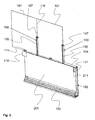
- FIG. 1 shows an exemplary ice-hockey rink board structure according to the invention when being mounted.
- the board element 102 is a parallelogrammic structure having ends 117, an upper edge 104 and a lower edge 103 as well as two sides: a side facing the rink and a side facing outwards, i.e., away from the rink.
- the side facing the rink is covered by a sheet 118, which sheet meets the requirements imposed by the International Ice-hockey Federation.
- the side facing outwards is also covered by a sheet.
- the support post guide 109 is shifted above the upper edge of the board element. This shift is denoted by a dashed line.
- the lower end of the support post guide is secured to the upper support structure 115 of the board element, and the upper end of the support post guide does not extend higher than to the level of the upper edge of the board element.
- the lower part of the board element comprises support structures making the lower edge 103 of the board element wider than the upper edge 104 of the board element. The widening takes place outwards from the rink, the board element side facing the rink thus being entirely flat.
- the lower edge 103 of the board element 102 is provided with fastening means for fastening it to the substrate.
- the ends 117 of the board element are provided with coupling means for coupling the board elements together at their ends. They can be openings 111 in the upper part of the end and openings 113 in the lower part of the end through which it is possible fasten the board elements to each other by means of bolts, for example.
- the openings 111 and 113 are positioned such that the fastening of the board elements can be carried out even if they were not entirely parallel to each other. Thus, it is possible to mount the board elements in the round corners of an ice-hockey rink.
- the board element has support structures for enhancing its stability.
- the board element has two horizontal support structures: an upper support structure 115 and a lower support structure 114. They are parallel to the upper and lower edges of the board element and interconnect the ends 117.
- the material of the body parts of the board element is aluminum, and the structures are beam-like. For lightness, they are usually hollow.
- the shielding panels 101 are parallelogrammic, thin sheets made from a transparent material.
- the shielding panels are made from a polycarbonate sheet. They are mounted on the upper edge of the board element to form a wall-like structure between the ice-hockey rink and the outside.
- the shielding panels are secured into place by means of support posts.
- the support post 100 is two parts, consisting of a first part 105 and a second part (not shown in Figure 1 ).
- the first part of the support post is an elongated hollow tube having one flat side as well as an upper end 106 and a lower end 108. The inside of the tube can be shaped. On the flat side of the first part, openings for inserting the fasteners are provided.
- the support post guide 109 is secured to the upper support structure 115 of the board element, under the hole.
- the support post guide is an elongated body having a flat plate disposed at its lower end and provided with holes by means of which the support post guide can be secured to the upper face of the upper support structure of the board element.
- the support post guide is dimensioned to fit at least partly into the first part 105 of the support post.
- the support post guide guides the first part of the support post into the right position and locks the lower end 108 of the first part of the support post into place. The shape of the inside of the first part of the support post facilitates this.
- first part 105 and the second part of the support post 100 as well as the support post guide 109 are made from aluminum
- a shielding panel support guide 110 is secured to the upper part 104 of the board element, between two support posts 100, approximately in the middle.
- the shielding panel support guide is shaped to be fastenable to the substrate by fasteners. Its side facing the shielding panel 101 is made straight.
- the shielding panel support guide is fastened to such a point that its straight side lies more or less flush with the outer face of the shielding panel, thereby preventing the shielding panel from moving away from the rink.
- the upper insert 107 of the support post is secured to the upper end 106 of the first part 105 of the support post.
- the upper insert of the support post partly enters the first part of the support post. It is positioned such that its smooth support face lies against the outer face of the shielding panel. It supports and guides the shielding panels 100 back to where they were between the first part and the second part of the support post, yields and returns to the straight state when a player bumps against the board structure, for example.
- the shielding panel support guide 110 and the upper insert 107 of the support post are made from injection-molded polycarbonate.
- the shielding panel support guide and the upper insert of the support post are at least partly transparent.
- the seam 116 between the shielding panels 101 a, 101b is placed at the support post, the fastener openings in the smooth face of the first part 105 of the support post facing the shielding panel then being visible in the seam.
- the first part 105a of the support post has not yet been mounted in the opening 112 in the upper edge of the board element. Neither has the upper insert 107 of the support post been put into place.
- the first part 105a and the second part of the support post 100 and the upper insert 107 of the support post have all been put into place.
- the shielding panels are made from a transparent material with suitable properties. It can be acrylic resin, polycarbonate or tempered glass, for example. In some cases, it is possible to use several different shielding panel materials in the same board structure.
- FIG. 2 the assembling of the ice-hockey rink board structure has been finished, the first parts and the second parts of the support posts 100 being in place.
- the side of the board element 102 facing outwards from the rink is covered by a sheet 201.
- the sheet extends from the upper edge 102 of the board element to the upper edge of the projecting support structures in the lower part of the board element.
- the fasteners provided in the lower part of the board element and fastening the board element to the adjacent board elements as well as to the substrate are reachable for removal, securing and service.
- a space 211 is provided for a service hatch.
- the space 211 is rectangular, and because the spaces in both corners of the sheet have substantially equal dimensions, the service hatch is positioned symmetrically.
- the service hatch provides access to the fasteners located in the upper parts of the board element and fastening the adjacent board elements together.
- the seam 116 between the shielding panels is so wide that the fastener openings provided in the smooth side of the first part 105, lying against the shielding panels, can be used.
- the second part of the support post (not shown in Figure 2 ) is disposed on the seam, on the rink side of the shielding elements.
- the second part of the support post is lath-like, substantially as wide as or slightly narrower than the first part of the support post.
- the side of the second part of the support post lying against the shielding panels is straight, while its side facing the rink is rounded.
- the second part of the support post comprises openings for fasteners.
- the second part of the support post is shorter than the first part of the support post.
- the upper end of the second part of the support post is flush with the upper end of the first part of support post inserted into the board element.
- the second part of the support post is mounted to cover the seam 116 between the shielding panels, and the fasteners fit into this seam.
- the fasteners are secured to extend through the seam, to the fastener openings of the first part of the support post.
- the fasteners When the fasteners are tightened, they pull the first part and the second part of the support post against each other, the first part and the second part of the support post simultaneously compressing the shielding panels between themselves.
- the first part of the support post has rivet nuts mounted in the fastener openings. They stay in place and do not fall even if the first part of the support post is moved.
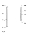
- Figure 3 shows an example of the support post 100 of an ice-hockey rink board structure according to the invention, consisting of a first part 301 and a second part 302.
- the first part 301 of the support post is an elongated hollow cylindrical body having one straight side. This straight side is placed against the shielding panels.
- the first part of the support post has an upper end 306 and a lower end 307.
- the straight side of the first part of the support post is provided with openings 305 for fasteners.
- openings 305 for fasteners.
- the upper insert of the support post is mounted in the upper end of the first part of the support post.
- the second part 302 of the support post is a lath-like body whose one side lying against the shielding panels is flat and whose other side is curved. Because the second part of the support post is placed on the rink side, its shape facing the rink has to be as smooth as possible.
- the second part of the support post has an upper end 308 and a lower end 309.
- the second part of the support post has openings 310 for fasteners.
- the opening shapes are preferably such that, when the fasteners are in place, their heads are optimally hidden so as to keep the face towards the rink as smooth as possible.
- the fastener openings in both parts of the support post are positioned such that, when the first part is mounted in the opening in the upper edge of the board element, the openings of the first part 301 and the second part 302 of the support post are aligned with each other. Then, the lower end 309 of the second part of the support post is flush with the upper edge of the board element, while the upper end 308 thereof is flush with the upper end 306 of the support post.
- the first part and the second part of the support post are fastened to each other so that the shielding panels and their seam are placed between them, by means of the rivet nuts provided in the second part of the second part of the support post, not shown in the Figure.
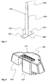
- Figure 4 is an example of the support post guide 109. It consists of plate-like parts, i.e. of a fastening part 401, a support part 402 and a guide part 404.
- the exemplary support post guide is fastened to the upper face of the upper support structure of the board element, under the opening in the upper edge of the board element.
- the fastening part is a parallelogrammic plate having openings 403 for fasteners.
- the support part 402 is also a parallelogrammic plate secured at one side to one side of the fastening part to form a substantially right angle therewith.
- the support part keeps the guide part in position.
- the guide part 404 is an elongated plate structure having an upper end 405 and a lower end 406.
- the guide part is shaped such that the upper end is narrower than the lower end.
- the guide part is secured to the fastening part and the support part, the guide part being in a vertical position in the direction of its longitudinal axis.
- the guide part is essentially dimensioned to not extend outside the opening in the upper edge of the board element located above it.
- the guide part tapers towards its upper end.
- the fastening part is secured to such a point of the upper support structure of the board element that, when the first part of the support post is inserted downwards through the opening in the upper edge of the board element, the guide part penetrates into the hollow first part of the support post, simultaneously guiding the first part of the support post into the right position, and locks the lower end of the first part of the post into place.
- Figure 5 shows an example of the upper insert 107 of the support post according to the invention. It has an upper face 501 and a smooth support face 503 against the shielding panel.
- the upper insert has a plug-like structure 504 adapted to fit into the upper end of the hollow first part of the support post.
- the substantially plug-like structure is shaped to follow the inside of the upper end of the first part of the support post.
- the plug-like structure is positioned such that, when it is mounted inside the first part of support post, the straight face of the first part of the support post essentially lies flush with the support face 503 of the upper insert of the support post.
- the upper insert extends the support applied to the shielding panels by the support post. If the shielding panels bend due to a violent hit or pressure, the support face of the upper insert guides the shielding panels back to where they were between the first part and the second part of the support post, the shielding panels thus returning to their original position.
- the lower guide of the support post can be a sleeve-like structure receiving the first part of the support post.
Landscapes
- Engineering & Computer Science (AREA)
- Architecture (AREA)
- Civil Engineering (AREA)
- Structural Engineering (AREA)
- Connection Of Plates (AREA)
- Devices Affording Protection Of Roads Or Walls For Sound Insulation (AREA)
- Road Signs Or Road Markings (AREA)
Claims (15)
- Structure de panneau pour une patinoire de hockey sur glace, comprenant des éléments de panneau interconnectables (102) ayant un bord supérieur (104), des panneaux de protection transparents (101) positionnés au-dessus des éléments de panneau et ayant un bord supérieur, ainsi que des montants de support (100) pour raccorder les panneaux de protection aux éléments de panneau, lesquels montants de support ont une extrémité supérieure, la distance entre l'extrémité supérieure du montant de support et le bord supérieur des éléments de panneau étant sensiblement plus courte que la distance entre le bord supérieur du panneau de protection et le bord supérieur de l'élément de panneau, caractérisée en ce que, au niveau de l'extrémité supérieure du montant de support, est agencé un insert supérieur (107), ayant une face de support (503) destinée à être placée contre le panneau de protection, la largeur de l'insert supérieur étant sensiblement supérieure à la largeur du montant de support.
- Structure de panneau pour une patinoire de hockey sur glace selon la revendication 1, caractérisée en ce que la distance entre l'extrémité supérieure du montant de support et le bord supérieur (104) de l'élément de panneau (102) est de 80 centimètres.
- Structure de panneau pour une patinoire de hockey sur glace selon la revendication 1, caractérisée en ce que le montant de support (100) comprend une première partie (105 ; 301) destinée à être agencée à l'extérieur du panneau de protection (101) et une seconde partie (302) destinée à être agencée du côté de la patinoire du panneau de protection, lesquelles première et seconde parties sont agencées pour être fixées de manière amovible ensemble par des fixations, les bords verticaux des panneaux de protection adjacente étant ainsi placés entre la première partie et la seconde partie.
- Structure de panneau pour une patinoire de hockey sur glace selon la revendication 1, caractérisée en ce que la première partie (105 ; 301) du montant de support (100) est creuse et la seconde partie (302) est en forme de latte.
- Structure de panneau pour une patinoire de hockey sur glace selon la revendication 1, caractérisée en ce que l'insert supérieur (107) du montant de support est agencé pour être monté dans l'extrémité supérieure (106 ; 306) de la première partie (105 ; 301) du montant de support (100), l'insert supériéur étant ainsi partiellement à l'intérieur de la première partie du montant de support et la face de support (503) de l'insert supérieur se trouvant contre la face externe du panneau de protection (101).
- Structure de panneau pour une patinoire de hockey sur glace selon la revendication 1, caractérisée en ce que le bord supérieur (104) de l'élément de panneau (102) comprend une ou plusieurs ouvertures (112) pouvant recevoir l'extrémité inférieure (108) de la première partie (105 ; 301) du montant de support (100), des guides de montant de support (109) étant agencés à l'intérieur de l'élément de panneau, au niveau desdites ouvertures, pour fixer l'extrémité inférieure de la première partie du montant de support,
- Structure de panneau pour une patinoire de hockey sur glace selon la revendication 5, caractérisée en ce que le guide de montant de support (109) est une structure allongée, agencée pour être positionnée au moins partiellement à l'intérieur de la première partie (105 ; 301) du montant de support (100) lorsque la première partie du montant de support est Montée dans l'ouverture (112) dans le bord supérieur (104) de l'élément de panneau (102).
- Structure de panneau pour une patinoire de hockey sur glace selon l'une quelconque des revendications 5 à 6, caractérisée en ce que l'élément de panneau (102) contient une structure de support supérieure horizontale (115) ayant le guide de montant de support (109) fixé à cette dernière.
- Structure de panneau pour une patinoire de hockey sur glace selon l'une quelconque des revendications 5 à 7, caractérisée en ce que l'extrémité supérieure (405) du guide de montant de support (109) ne s'étend pas plus haut que le niveau de la surface du bord supérieur (104) de l'élément de panneau (102).
- Structure de panneau pour une patinoire de hockey sur glace selon l'une quelconque des revendications 1 à 9, caractérisée en ce que les fixations fixant la première partie (105 ; 301) et la seconde partie (305) du montant de support (100) entre elles, sont agencées pour être fixées en place à partir de la direction de la seconde partie du montant de support.
- Structure de panneau pour une patinoire de hockey sur glace selon l'une quelconque des revendications 1 à 10, caractérisée en ce que les fixations du montant de support (100) sont des écrous de rivet et prévues sur la première partie (302) du montant de support.
- Structure de panneau pour une patinoire de hockey sur glace selon la revendication 1, caractérisée en ce que le bord supérieur (104) de l'élément de panneau (102) comprend également au moins un ou plusieurs guides de support de panneau de protection (110), son côté faisant face à la patinoire est une face de support destinée à être placée contre la surface du panneau de protection (101).
- Structure de panneau pour une patinoire de hockey sur glace selon l'une quelconque des revendications 1 à 12, caractérisée en ce que l'insert supérieur (107) du montant de support et le guide de support de panneau de protection (110) sont au moins partiellement réalisés à partir d'un matériau transparent.
- Structure de panneau pour une patinoire de hockey sur glace selon l'une quelconque des revendications 1 à 13, caractérisée en ce que le panneau de protection (101) est réalisé à partir de polycarbonate.
- Structure de panneau pour une patinoire de hockey sur glace selon l'une quelconque des revendications 1 à 14, caractérisée en ce que le montant de support (100) est réalisé à partir d'aluminium.
Applications Claiming Priority (2)
| Application Number | Priority Date | Filing Date | Title |
|---|---|---|---|
| FI20075457A FI20075457L (fi) | 2007-06-15 | 2007-06-15 | Jääkiekkokaukalon laitarakenne |
| PCT/FI2008/050364 WO2008152210A1 (fr) | 2007-06-15 | 2008-06-16 | Structure de panneau pour une patinoire de hockey sur glace |
Publications (3)
| Publication Number | Publication Date |
|---|---|
| EP2170471A1 EP2170471A1 (fr) | 2010-04-07 |
| EP2170471A4 EP2170471A4 (fr) | 2013-01-02 |
| EP2170471B1 true EP2170471B1 (fr) | 2014-04-09 |
Family
ID=38212428
Family Applications (1)
| Application Number | Title | Priority Date | Filing Date |
|---|---|---|---|
| EP08775489.1A Not-in-force EP2170471B1 (fr) | 2007-06-15 | 2008-06-16 | Structure de panneau pour une patinoire de hockey sur glace |
Country Status (4)
| Country | Link |
|---|---|
| EP (1) | EP2170471B1 (fr) |
| FI (1) | FI20075457L (fr) |
| RU (1) | RU2010100941A (fr) |
| WO (1) | WO2008152210A1 (fr) |
Cited By (2)
| Publication number | Priority date | Publication date | Assignee | Title |
|---|---|---|---|---|
| US20150328531A1 (en) * | 2013-07-11 | 2015-11-19 | Dean L. Sicking | Energy absorbing sports board |
| RU207969U1 (ru) * | 2021-08-21 | 2021-11-29 | Общество с ограниченной ответственностью «Простор-Л» | Стойка крепления защитного светопрозрачного ограждения борта хоккейной площадки |
Families Citing this family (1)
| Publication number | Priority date | Publication date | Assignee | Title |
|---|---|---|---|---|
| GB0904617D0 (en) * | 2009-03-18 | 2009-04-29 | 1196501 Ontario Inc | Dasher-board system with flush-mounted glass |
Family Cites Families (7)
| Publication number | Priority date | Publication date | Assignee | Title |
|---|---|---|---|---|
| US4927134A (en) * | 1988-07-01 | 1990-05-22 | Burley's Ring Supply | Dasher board system |
| US6155022A (en) * | 1997-12-09 | 2000-12-05 | Athletica, Inc. | Shielding panel removal and installation system for supportless dasher boards |
| US6004217A (en) * | 1998-01-19 | 1999-12-21 | Athletica, Inc. | Flexible dasher board system |
| US6095503A (en) * | 1998-03-11 | 2000-08-01 | Burley's Rink Supply, Inc. | Dasher board system |
| US6349517B1 (en) * | 2000-03-30 | 2002-02-26 | Cubic Corporation | Fixed barrier module |
| US6622434B1 (en) * | 2000-05-24 | 2003-09-23 | Wayne Kenneth Garrett | Safety enclosure shield panel support system |
| US7434790B1 (en) * | 2006-05-17 | 2008-10-14 | Hansen Tracy C | Vertical panel glass wall |
-
2007
- 2007-06-15 FI FI20075457A patent/FI20075457L/fi unknown
-
2008
- 2008-06-16 WO PCT/FI2008/050364 patent/WO2008152210A1/fr not_active Ceased
- 2008-06-16 RU RU2010100941/12A patent/RU2010100941A/ru not_active Application Discontinuation
- 2008-06-16 EP EP08775489.1A patent/EP2170471B1/fr not_active Not-in-force
Cited By (2)
| Publication number | Priority date | Publication date | Assignee | Title |
|---|---|---|---|---|
| US20150328531A1 (en) * | 2013-07-11 | 2015-11-19 | Dean L. Sicking | Energy absorbing sports board |
| RU207969U1 (ru) * | 2021-08-21 | 2021-11-29 | Общество с ограниченной ответственностью «Простор-Л» | Стойка крепления защитного светопрозрачного ограждения борта хоккейной площадки |
Also Published As
| Publication number | Publication date |
|---|---|
| RU2010100941A (ru) | 2011-07-20 |
| WO2008152210A1 (fr) | 2008-12-18 |
| FI20075457A0 (sv) | 2007-06-15 |
| EP2170471A1 (fr) | 2010-04-07 |
| FI20075457A7 (fi) | 2008-12-16 |
| EP2170471A4 (fr) | 2013-01-02 |
| FI20075457L (fi) | 2008-12-16 |
Similar Documents
| Publication | Publication Date | Title |
|---|---|---|
| US4905970A (en) | Dasher board system for athletic playing surfaces | |
| US4373720A (en) | Tennis practice backboard | |
| US5706625A (en) | Supportless dasher board | |
| EP3940174B1 (fr) | Clôture et procedée de construction de ladite clôture | |
| US6004217A (en) | Flexible dasher board system | |
| US7914385B2 (en) | Dasher boards | |
| EP4251290B1 (fr) | Construction de court de padel | |
| EP2170471B1 (fr) | Structure de panneau pour une patinoire de hockey sur glace | |
| US9082325B2 (en) | Platform system, video module assembly, and process of assembling platform system | |
| CA2259767A1 (fr) | Systeme de panneaux de bande pour patinoire | |
| US11261616B2 (en) | Modular fence system | |
| CA3015329A1 (fr) | Systeme de cloture | |
| US20030032490A1 (en) | Glass laminate system for hockey rinks | |
| US6622434B1 (en) | Safety enclosure shield panel support system | |
| US20070054742A1 (en) | Gaming cabinet construction and method | |
| US20060169965A1 (en) | Pre-fabricated fencing panels | |
| US6796361B1 (en) | Hurricane I-post | |
| US10358820B2 (en) | Modular building system and a method of assembling building elements to construct such building system | |
| WO2012120188A1 (fr) | Structure de plaque d'une patinoire pour hockey | |
| CA2170943C (fr) | Planche de bord sans support | |
| EP2019279A2 (fr) | Assemblage de cible de jeu de fléchettes | |
| WO1993025285A2 (fr) | Poteau de but portable | |
| RU43470U1 (ru) | Система крепления щитов защитного светопрозрачного ограждения на хоккейном борту | |
| US7204764B2 (en) | Hockey safety net | |
| US20050285012A1 (en) | Security support assembly |
Legal Events
| Date | Code | Title | Description |
|---|---|---|---|
| PUAI | Public reference made under article 153(3) epc to a published international application that has entered the european phase |
Free format text: ORIGINAL CODE: 0009012 |
|
| 17P | Request for examination filed |
Effective date: 20100113 |
|
| AK | Designated contracting states |
Kind code of ref document: A1 Designated state(s): AT BE BG CH CY CZ DE DK EE ES FI FR GB GR HR HU IE IS IT LI LT LU LV MC MT NL NO PL PT RO SE SI SK TR |
|
| AX | Request for extension of the european patent |
Extension state: AL BA MK RS |
|
| DAX | Request for extension of the european patent (deleted) | ||
| REG | Reference to a national code |
Ref country code: DE Ref legal event code: R079 Ref document number: 602008031417 Country of ref document: DE Free format text: PREVIOUS MAIN CLASS: A63C0019100000 Ipc: A63C0019060000 |
|
| A4 | Supplementary search report drawn up and despatched |
Effective date: 20121204 |
|
| RIC1 | Information provided on ipc code assigned before grant |
Ipc: A63C 19/06 20060101AFI20121128BHEP Ipc: A63C 19/10 20060101ALI20121128BHEP |
|
| GRAP | Despatch of communication of intention to grant a patent |
Free format text: ORIGINAL CODE: EPIDOSNIGR1 |
|
| INTG | Intention to grant announced |
Effective date: 20131115 |
|
| GRAS | Grant fee paid |
Free format text: ORIGINAL CODE: EPIDOSNIGR3 |
|
| GRAA | (expected) grant |
Free format text: ORIGINAL CODE: 0009210 |
|
| AK | Designated contracting states |
Kind code of ref document: B1 Designated state(s): AT BE BG CH CY CZ DE DK EE ES FI FR GB GR HR HU IE IS IT LI LT LU LV MC MT NL NO PL PT RO SE SI SK TR |
|
| REG | Reference to a national code |
Ref country code: GB Ref legal event code: FG4D |
|
| REG | Reference to a national code |
Ref country code: AT Ref legal event code: REF Ref document number: 661010 Country of ref document: AT Kind code of ref document: T Effective date: 20140415 Ref country code: CH Ref legal event code: EP |
|
| REG | Reference to a national code |
Ref country code: IE Ref legal event code: FG4D |
|
| REG | Reference to a national code |
Ref country code: DE Ref legal event code: R096 Ref document number: 602008031417 Country of ref document: DE Effective date: 20140522 |
|
| REG | Reference to a national code |
Ref country code: SE Ref legal event code: TRGR |
|
| REG | Reference to a national code |
Ref country code: AT Ref legal event code: MK05 Ref document number: 661010 Country of ref document: AT Kind code of ref document: T Effective date: 20140409 |
|
| REG | Reference to a national code |
Ref country code: NL Ref legal event code: VDEP Effective date: 20140409 |
|
| REG | Reference to a national code |
Ref country code: NO Ref legal event code: T2 Effective date: 20140409 |
|
| REG | Reference to a national code |
Ref country code: LT Ref legal event code: MG4D |
|
| PG25 | Lapsed in a contracting state [announced via postgrant information from national office to epo] |
Ref country code: IS Free format text: LAPSE BECAUSE OF FAILURE TO SUBMIT A TRANSLATION OF THE DESCRIPTION OR TO PAY THE FEE WITHIN THE PRESCRIBED TIME-LIMIT Effective date: 20140809 Ref country code: LT Free format text: LAPSE BECAUSE OF FAILURE TO SUBMIT A TRANSLATION OF THE DESCRIPTION OR TO PAY THE FEE WITHIN THE PRESCRIBED TIME-LIMIT Effective date: 20140409 Ref country code: NL Free format text: LAPSE BECAUSE OF FAILURE TO SUBMIT A TRANSLATION OF THE DESCRIPTION OR TO PAY THE FEE WITHIN THE PRESCRIBED TIME-LIMIT Effective date: 20140409 Ref country code: GR Free format text: LAPSE BECAUSE OF FAILURE TO SUBMIT A TRANSLATION OF THE DESCRIPTION OR TO PAY THE FEE WITHIN THE PRESCRIBED TIME-LIMIT Effective date: 20140710 Ref country code: BG Free format text: LAPSE BECAUSE OF FAILURE TO SUBMIT A TRANSLATION OF THE DESCRIPTION OR TO PAY THE FEE WITHIN THE PRESCRIBED TIME-LIMIT Effective date: 20140709 |
|
| PG25 | Lapsed in a contracting state [announced via postgrant information from national office to epo] |
Ref country code: HR Free format text: LAPSE BECAUSE OF FAILURE TO SUBMIT A TRANSLATION OF THE DESCRIPTION OR TO PAY THE FEE WITHIN THE PRESCRIBED TIME-LIMIT Effective date: 20140409 Ref country code: PL Free format text: LAPSE BECAUSE OF FAILURE TO SUBMIT A TRANSLATION OF THE DESCRIPTION OR TO PAY THE FEE WITHIN THE PRESCRIBED TIME-LIMIT Effective date: 20140409 Ref country code: LV Free format text: LAPSE BECAUSE OF FAILURE TO SUBMIT A TRANSLATION OF THE DESCRIPTION OR TO PAY THE FEE WITHIN THE PRESCRIBED TIME-LIMIT Effective date: 20140409 Ref country code: ES Free format text: LAPSE BECAUSE OF FAILURE TO SUBMIT A TRANSLATION OF THE DESCRIPTION OR TO PAY THE FEE WITHIN THE PRESCRIBED TIME-LIMIT Effective date: 20140409 Ref country code: AT Free format text: LAPSE BECAUSE OF FAILURE TO SUBMIT A TRANSLATION OF THE DESCRIPTION OR TO PAY THE FEE WITHIN THE PRESCRIBED TIME-LIMIT Effective date: 20140409 |
|
| PG25 | Lapsed in a contracting state [announced via postgrant information from national office to epo] |
Ref country code: PT Free format text: LAPSE BECAUSE OF FAILURE TO SUBMIT A TRANSLATION OF THE DESCRIPTION OR TO PAY THE FEE WITHIN THE PRESCRIBED TIME-LIMIT Effective date: 20140811 |
|
| REG | Reference to a national code |
Ref country code: DE Ref legal event code: R097 Ref document number: 602008031417 Country of ref document: DE |
|
| PG25 | Lapsed in a contracting state [announced via postgrant information from national office to epo] |
Ref country code: CZ Free format text: LAPSE BECAUSE OF FAILURE TO SUBMIT A TRANSLATION OF THE DESCRIPTION OR TO PAY THE FEE WITHIN THE PRESCRIBED TIME-LIMIT Effective date: 20140409 Ref country code: EE Free format text: LAPSE BECAUSE OF FAILURE TO SUBMIT A TRANSLATION OF THE DESCRIPTION OR TO PAY THE FEE WITHIN THE PRESCRIBED TIME-LIMIT Effective date: 20140409 Ref country code: RO Free format text: LAPSE BECAUSE OF FAILURE TO SUBMIT A TRANSLATION OF THE DESCRIPTION OR TO PAY THE FEE WITHIN THE PRESCRIBED TIME-LIMIT Effective date: 20140409 Ref country code: DK Free format text: LAPSE BECAUSE OF FAILURE TO SUBMIT A TRANSLATION OF THE DESCRIPTION OR TO PAY THE FEE WITHIN THE PRESCRIBED TIME-LIMIT Effective date: 20140409 Ref country code: SK Free format text: LAPSE BECAUSE OF FAILURE TO SUBMIT A TRANSLATION OF THE DESCRIPTION OR TO PAY THE FEE WITHIN THE PRESCRIBED TIME-LIMIT Effective date: 20140409 Ref country code: BE Free format text: LAPSE BECAUSE OF FAILURE TO SUBMIT A TRANSLATION OF THE DESCRIPTION OR TO PAY THE FEE WITHIN THE PRESCRIBED TIME-LIMIT Effective date: 20140409 Ref country code: MC Free format text: LAPSE BECAUSE OF FAILURE TO SUBMIT A TRANSLATION OF THE DESCRIPTION OR TO PAY THE FEE WITHIN THE PRESCRIBED TIME-LIMIT Effective date: 20140409 Ref country code: LU Free format text: LAPSE BECAUSE OF FAILURE TO SUBMIT A TRANSLATION OF THE DESCRIPTION OR TO PAY THE FEE WITHIN THE PRESCRIBED TIME-LIMIT Effective date: 20140616 |
|
| PLBE | No opposition filed within time limit |
Free format text: ORIGINAL CODE: 0009261 |
|
| STAA | Information on the status of an ep patent application or granted ep patent |
Free format text: STATUS: NO OPPOSITION FILED WITHIN TIME LIMIT |
|
| 26N | No opposition filed |
Effective date: 20150112 |
|
| REG | Reference to a national code |
Ref country code: IE Ref legal event code: MM4A |
|
| PG25 | Lapsed in a contracting state [announced via postgrant information from national office to epo] |
Ref country code: IT Free format text: LAPSE BECAUSE OF FAILURE TO SUBMIT A TRANSLATION OF THE DESCRIPTION OR TO PAY THE FEE WITHIN THE PRESCRIBED TIME-LIMIT Effective date: 20140409 |
|
| REG | Reference to a national code |
Ref country code: DE Ref legal event code: R097 Ref document number: 602008031417 Country of ref document: DE Effective date: 20150112 |
|
| PG25 | Lapsed in a contracting state [announced via postgrant information from national office to epo] |
Ref country code: IE Free format text: LAPSE BECAUSE OF NON-PAYMENT OF DUE FEES Effective date: 20140616 |
|
| PG25 | Lapsed in a contracting state [announced via postgrant information from national office to epo] |
Ref country code: SI Free format text: LAPSE BECAUSE OF FAILURE TO SUBMIT A TRANSLATION OF THE DESCRIPTION OR TO PAY THE FEE WITHIN THE PRESCRIBED TIME-LIMIT Effective date: 20140409 |
|
| PG25 | Lapsed in a contracting state [announced via postgrant information from national office to epo] |
Ref country code: MT Free format text: LAPSE BECAUSE OF FAILURE TO SUBMIT A TRANSLATION OF THE DESCRIPTION OR TO PAY THE FEE WITHIN THE PRESCRIBED TIME-LIMIT Effective date: 20140409 |
|
| PG25 | Lapsed in a contracting state [announced via postgrant information from national office to epo] |
Ref country code: CY Free format text: LAPSE BECAUSE OF FAILURE TO SUBMIT A TRANSLATION OF THE DESCRIPTION OR TO PAY THE FEE WITHIN THE PRESCRIBED TIME-LIMIT Effective date: 20140409 |
|
| REG | Reference to a national code |
Ref country code: FR Ref legal event code: PLFP Year of fee payment: 9 |
|
| PG25 | Lapsed in a contracting state [announced via postgrant information from national office to epo] |
Ref country code: HU Free format text: LAPSE BECAUSE OF FAILURE TO SUBMIT A TRANSLATION OF THE DESCRIPTION OR TO PAY THE FEE WITHIN THE PRESCRIBED TIME-LIMIT; INVALID AB INITIO Effective date: 20080616 Ref country code: TR Free format text: LAPSE BECAUSE OF FAILURE TO SUBMIT A TRANSLATION OF THE DESCRIPTION OR TO PAY THE FEE WITHIN THE PRESCRIBED TIME-LIMIT Effective date: 20140409 |
|
| REG | Reference to a national code |
Ref country code: FR Ref legal event code: PLFP Year of fee payment: 10 |
|
| REG | Reference to a national code |
Ref country code: FR Ref legal event code: PLFP Year of fee payment: 11 |
|
| PGFP | Annual fee paid to national office [announced via postgrant information from national office to epo] |
Ref country code: CH Payment date: 20200618 Year of fee payment: 13 Ref country code: DE Payment date: 20200618 Year of fee payment: 13 Ref country code: NO Payment date: 20200619 Year of fee payment: 13 |
|
| PGFP | Annual fee paid to national office [announced via postgrant information from national office to epo] |
Ref country code: GB Payment date: 20200617 Year of fee payment: 13 Ref country code: SE Payment date: 20200616 Year of fee payment: 13 |
|
| REG | Reference to a national code |
Ref country code: CH Ref legal event code: PLI Free format text: NON-EXCLUSIVE LICENCE Name of requester: ICEPRO OY, FI |
|
| REG | Reference to a national code |
Ref country code: NO Ref legal event code: LIS Free format text: LISENSKATEGORI IKKE-EKSKLUSIV Name of requester: ICEPRO OY, RATAKATU 13, 84100 YLIVIESKA, FINLAND (FI) |
|
| REG | Reference to a national code |
Ref country code: GB Ref legal event code: 732E Free format text: REGISTERED BETWEEN 20201203 AND 20201209 |
|
| REG | Reference to a national code |
Ref country code: DE Ref legal event code: R119 Ref document number: 602008031417 Country of ref document: DE |
|
| REG | Reference to a national code |
Ref country code: NO Ref legal event code: MMEP |
|
| REG | Reference to a national code |
Ref country code: SE Ref legal event code: EUG |
|
| REG | Reference to a national code |
Ref country code: CH Ref legal event code: PL |
|
| GBPC | Gb: european patent ceased through non-payment of renewal fee |
Effective date: 20210616 |
|
| PG25 | Lapsed in a contracting state [announced via postgrant information from national office to epo] |
Ref country code: LI Free format text: LAPSE BECAUSE OF NON-PAYMENT OF DUE FEES Effective date: 20210630 Ref country code: GB Free format text: LAPSE BECAUSE OF NON-PAYMENT OF DUE FEES Effective date: 20210616 Ref country code: DE Free format text: LAPSE BECAUSE OF NON-PAYMENT OF DUE FEES Effective date: 20220101 Ref country code: CH Free format text: LAPSE BECAUSE OF NON-PAYMENT OF DUE FEES Effective date: 20210630 |
|
| PG25 | Lapsed in a contracting state [announced via postgrant information from national office to epo] |
Ref country code: SE Free format text: LAPSE BECAUSE OF NON-PAYMENT OF DUE FEES Effective date: 20210617 Ref country code: NO Free format text: LAPSE BECAUSE OF NON-PAYMENT OF DUE FEES Effective date: 20210630 |
|
| PGFP | Annual fee paid to national office [announced via postgrant information from national office to epo] |
Ref country code: FI Payment date: 20220621 Year of fee payment: 15 |
|
| PGFP | Annual fee paid to national office [announced via postgrant information from national office to epo] |
Ref country code: FR Payment date: 20220614 Year of fee payment: 15 |
|
| PG25 | Lapsed in a contracting state [announced via postgrant information from national office to epo] |
Ref country code: FI Free format text: LAPSE BECAUSE OF NON-PAYMENT OF DUE FEES Effective date: 20230616 |
|
| PG25 | Lapsed in a contracting state [announced via postgrant information from national office to epo] |
Ref country code: FR Free format text: LAPSE BECAUSE OF NON-PAYMENT OF DUE FEES Effective date: 20230630 |