EP2170667B1 - Procédé pour mesurer la pression d'alimentation au niveau d'une soupape hydraulique analoguée, à commande électromagnétique - Google Patents
Procédé pour mesurer la pression d'alimentation au niveau d'une soupape hydraulique analoguée, à commande électromagnétique Download PDFInfo
- Publication number
- EP2170667B1 EP2170667B1 EP08750294A EP08750294A EP2170667B1 EP 2170667 B1 EP2170667 B1 EP 2170667B1 EP 08750294 A EP08750294 A EP 08750294A EP 08750294 A EP08750294 A EP 08750294A EP 2170667 B1 EP2170667 B1 EP 2170667B1
- Authority
- EP
- European Patent Office
- Prior art keywords
- valve
- pressure
- hydraulic
- tappet
- pump
- Prior art date
- Legal status (The legal status is an assumption and is not a legal conclusion. Google has not performed a legal analysis and makes no representation as to the accuracy of the status listed.)
- Not-in-force
Links
- 238000000034 method Methods 0.000 title claims abstract description 23
- 230000001105 regulatory effect Effects 0.000 claims abstract description 6
- 230000004907 flux Effects 0.000 claims description 6
- 230000006698 induction Effects 0.000 claims description 4
- 230000004913 activation Effects 0.000 claims 1
- 238000010079 rubber tapping Methods 0.000 claims 1
- 238000002955 isolation Methods 0.000 description 5
- 230000033228 biological regulation Effects 0.000 description 3
- 238000009530 blood pressure measurement Methods 0.000 description 3
- 230000001419 dependent effect Effects 0.000 description 2
- 238000011156 evaluation Methods 0.000 description 2
- 239000012530 fluid Substances 0.000 description 2
- 238000004519 manufacturing process Methods 0.000 description 2
- 238000005259 measurement Methods 0.000 description 2
- 230000010349 pulsation Effects 0.000 description 2
- 230000001276 controlling effect Effects 0.000 description 1
- 238000013461 design Methods 0.000 description 1
- 238000012544 monitoring process Methods 0.000 description 1
- 238000011144 upstream manufacturing Methods 0.000 description 1
Images

Classifications
-
- B—PERFORMING OPERATIONS; TRANSPORTING
- B60—VEHICLES IN GENERAL
- B60T—VEHICLE BRAKE CONTROL SYSTEMS OR PARTS THEREOF; BRAKE CONTROL SYSTEMS OR PARTS THEREOF, IN GENERAL; ARRANGEMENT OF BRAKING ELEMENTS ON VEHICLES IN GENERAL; PORTABLE DEVICES FOR PREVENTING UNWANTED MOVEMENT OF VEHICLES; VEHICLE MODIFICATIONS TO FACILITATE COOLING OF BRAKES
- B60T8/00—Arrangements for adjusting wheel-braking force to meet varying vehicular or ground-surface conditions, e.g. limiting or varying distribution of braking force
- B60T8/32—Arrangements for adjusting wheel-braking force to meet varying vehicular or ground-surface conditions, e.g. limiting or varying distribution of braking force responsive to a speed condition, e.g. acceleration or deceleration
- B60T8/34—Arrangements for adjusting wheel-braking force to meet varying vehicular or ground-surface conditions, e.g. limiting or varying distribution of braking force responsive to a speed condition, e.g. acceleration or deceleration having a fluid pressure regulator responsive to a speed condition
- B60T8/36—Arrangements for adjusting wheel-braking force to meet varying vehicular or ground-surface conditions, e.g. limiting or varying distribution of braking force responsive to a speed condition, e.g. acceleration or deceleration having a fluid pressure regulator responsive to a speed condition including a pilot valve responding to an electromagnetic force
-
- B—PERFORMING OPERATIONS; TRANSPORTING
- B60—VEHICLES IN GENERAL
- B60T—VEHICLE BRAKE CONTROL SYSTEMS OR PARTS THEREOF; BRAKE CONTROL SYSTEMS OR PARTS THEREOF, IN GENERAL; ARRANGEMENT OF BRAKING ELEMENTS ON VEHICLES IN GENERAL; PORTABLE DEVICES FOR PREVENTING UNWANTED MOVEMENT OF VEHICLES; VEHICLE MODIFICATIONS TO FACILITATE COOLING OF BRAKES
- B60T8/00—Arrangements for adjusting wheel-braking force to meet varying vehicular or ground-surface conditions, e.g. limiting or varying distribution of braking force
- B60T8/32—Arrangements for adjusting wheel-braking force to meet varying vehicular or ground-surface conditions, e.g. limiting or varying distribution of braking force responsive to a speed condition, e.g. acceleration or deceleration
- B60T8/34—Arrangements for adjusting wheel-braking force to meet varying vehicular or ground-surface conditions, e.g. limiting or varying distribution of braking force responsive to a speed condition, e.g. acceleration or deceleration having a fluid pressure regulator responsive to a speed condition
- B60T8/36—Arrangements for adjusting wheel-braking force to meet varying vehicular or ground-surface conditions, e.g. limiting or varying distribution of braking force responsive to a speed condition, e.g. acceleration or deceleration having a fluid pressure regulator responsive to a speed condition including a pilot valve responding to an electromagnetic force
- B60T8/3615—Electromagnetic valves specially adapted for anti-lock brake and traction control systems
- B60T8/3655—Continuously controlled electromagnetic valves
-
- B—PERFORMING OPERATIONS; TRANSPORTING
- B60—VEHICLES IN GENERAL
- B60T—VEHICLE BRAKE CONTROL SYSTEMS OR PARTS THEREOF; BRAKE CONTROL SYSTEMS OR PARTS THEREOF, IN GENERAL; ARRANGEMENT OF BRAKING ELEMENTS ON VEHICLES IN GENERAL; PORTABLE DEVICES FOR PREVENTING UNWANTED MOVEMENT OF VEHICLES; VEHICLE MODIFICATIONS TO FACILITATE COOLING OF BRAKES
- B60T8/00—Arrangements for adjusting wheel-braking force to meet varying vehicular or ground-surface conditions, e.g. limiting or varying distribution of braking force
- B60T8/32—Arrangements for adjusting wheel-braking force to meet varying vehicular or ground-surface conditions, e.g. limiting or varying distribution of braking force responsive to a speed condition, e.g. acceleration or deceleration
- B60T8/34—Arrangements for adjusting wheel-braking force to meet varying vehicular or ground-surface conditions, e.g. limiting or varying distribution of braking force responsive to a speed condition, e.g. acceleration or deceleration having a fluid pressure regulator responsive to a speed condition
- B60T8/40—Arrangements for adjusting wheel-braking force to meet varying vehicular or ground-surface conditions, e.g. limiting or varying distribution of braking force responsive to a speed condition, e.g. acceleration or deceleration having a fluid pressure regulator responsive to a speed condition comprising an additional fluid circuit including fluid pressurising means for modifying the pressure of the braking fluid, e.g. including wheel driven pumps for detecting a speed condition, or pumps which are controlled by means independent of the braking system
- B60T8/404—Control of the pump unit
- B60T8/4059—Control of the pump unit involving the rate of delivery
-
- B—PERFORMING OPERATIONS; TRANSPORTING
- B60—VEHICLES IN GENERAL
- B60T—VEHICLE BRAKE CONTROL SYSTEMS OR PARTS THEREOF; BRAKE CONTROL SYSTEMS OR PARTS THEREOF, IN GENERAL; ARRANGEMENT OF BRAKING ELEMENTS ON VEHICLES IN GENERAL; PORTABLE DEVICES FOR PREVENTING UNWANTED MOVEMENT OF VEHICLES; VEHICLE MODIFICATIONS TO FACILITATE COOLING OF BRAKES
- B60T8/00—Arrangements for adjusting wheel-braking force to meet varying vehicular or ground-surface conditions, e.g. limiting or varying distribution of braking force
- B60T8/32—Arrangements for adjusting wheel-braking force to meet varying vehicular or ground-surface conditions, e.g. limiting or varying distribution of braking force responsive to a speed condition, e.g. acceleration or deceleration
- B60T8/34—Arrangements for adjusting wheel-braking force to meet varying vehicular or ground-surface conditions, e.g. limiting or varying distribution of braking force responsive to a speed condition, e.g. acceleration or deceleration having a fluid pressure regulator responsive to a speed condition
- B60T8/48—Arrangements for adjusting wheel-braking force to meet varying vehicular or ground-surface conditions, e.g. limiting or varying distribution of braking force responsive to a speed condition, e.g. acceleration or deceleration having a fluid pressure regulator responsive to a speed condition connecting the brake actuator to an alternative or additional source of fluid pressure, e.g. traction control systems
- B60T8/4809—Traction control, stability control, using both the wheel brakes and other automatic braking systems
- B60T8/4827—Traction control, stability control, using both the wheel brakes and other automatic braking systems in hydraulic brake systems
- B60T8/4863—Traction control, stability control, using both the wheel brakes and other automatic braking systems in hydraulic brake systems closed systems
- B60T8/4872—Traction control, stability control, using both the wheel brakes and other automatic braking systems in hydraulic brake systems closed systems pump-back systems
Definitions
- the invention relates to a method according to the preamble of claim 1 and its use.
- ACC longitudinal control
- an analogously regulating, electrically controllable hydraulic isolation valve is used, this permitting, in contrast to a control with an analogously controlled intake valve, a brake circuit-comprehensive pressure control.
- the hydraulic valves used for pressure control are usually conventional solenoid-operated seat valves, which are designed for switching. However, if these are controlled by means of a pulse-width-modulated current (PWM) in such a way that the valve tappet assumes a floating position, an analog control of the flow is also possible.
- PWM pulse-width-modulated current
- the WO 2007/025951 (P 11192) describes a method for determining a prevailing between a master cylinder and an intake valve of a wheel brake cylinder of a motor vehicle brake form which the form under consideration of the course of a tracking voltage of a clocked motor of a pump, which for the return promotion of brake fluid from a low-pressure accumulator in the master cylinder is used, determined.
- electrical characteristics of the voltage curve are measured and used in each case for determining a form pressure value.
- this method it is still not possible to determine with sufficient accuracy the pressure caused by the pump.
- P 10991 is a method for determining the pressure of a fluid or of the present at an electromagnetically controllable control valve differential pressure is known in which the pressure control valve is used for pressure measurement.
- the pressure control valve comprises the usual components of an electrohydraulic pressure control valve, such as exciter coil, valve tappets, valve domes, etc.
- the pressure measurement takes place via an electronic control loop, which regulates the position of the valve actuator or the magnetic force.
- the quantity used for regulation which is used as the actual value, represents the hydraulic force acting on the valve stem.
- the measurement of this force is carried out by measuring the corresponding magnetic force, which can be determined from the voltage induced in the region of the exciter coil.
- the object of the present invention is now an electronic pressure control device with functional components to operate particularly economically and quietly for an active pressure build-up.
- the invention is based on the idea to set the best possible form in the valve control in the analogized valve control.
- the admission pressure is higher by a certain amount than the pressure at the outlet side of the valve.
- the overflow pressure refers to the pressure which is produced during an active pressure build-up by a motor pump assembly in front of the isolation valve on the side upstream of the pump outlet and the wheel inlet valves, for example during a distance control (ACC).
- ACC distance control
- the admission pressure or overflow pressure in an isolation valve control is therefore determined essentially by the speed and duty cycle of the pump motor and the opening position of the isolation valve.
- a setpoint value for the motor of the motor pump unit is preferably predetermined according to the invention, wherein an electrical value is determined when determining the desired value Signal from the ram position loop is included.
- the admission pressure is set by electronic evaluation of the plunger reaction of a valve.
- the term "plunger reaction” is intended to include, besides the case of a plunger movement caused by a pressure change, also the case where only the drive electronics of the corresponding valve respond to a pressure change on the valve by a current change without the plunger position changing appreciably. So it is also possible that only the balance of power changes, since, for example, due to a higher pressure difference, a larger valve current must be set.
- An evaluation of the plunger reaction is preferably possible with the control loop described above when the plunger is in or near an equilibrium of forces between the magnetic force (minus or plus the valve spring force) and the hydraulic force. If the forces are far apart, the ram can not react to a pressure change.
- the ram reaction can be observed at the valve where the pre-pressure is to be determined or at another valve.
- any electromagnetically controlled hydraulic valve can be used for this purpose, provided that this is connected to the output side of the motor pump unit via pressure line.
- the plunger reaction in particular the plunger position or the hydraulic force, is preferably determined by means of an electric plunger position control loop.
- TPM Transpet Position Monitoring
- a measurement of the differential pressure at the metering valve is performed.
- the TPM (Tapet Position Monitoring) method makes it possible to move the plunger in one position set electromagnetically controlled valve or acting on the plunger of the valve force by means of a scheme and in particular to measure.
- the invention also relates to an electronically controlled motor vehicle brake pressure control device according to claim 10.
- Tandem master cylinder 5 is connected to hydraulic unit 6 (HCU) of an electronic vehicle brake system.
- Electronic unit 7 comprises a microprocessor / controllerystem with which the actuators and sensors contained in the valve block can be electronically controlled or measured.
- Hydraulic unit 6 is divided into two brake circuits I and II.
- each of the brake circuits comprises two wheel pressure circuits (A, B or C, D), each with an inlet 3 or 3 'and an outlet valve 4 or 4'.
- the electronics of the ECU 7 comprises a multi-channel current regulator which allows independent control of the currents through the coils of the isolation valves 2, 2 'and the inlet valves 3, 3'.
- Reference numerals 8 and 8 ' denote normally closed electronic switching valves.
- hydraulic line 8 In the leading to the master cylinder 5 hydraulic line 8 is an input pressure sensor 9.
- Motor-pump unit 1 or 1 ' is used for the active pressure build-up in ACC, TCS and ESP regulations and for the return promotion of the leaking at the exhaust pressure means, which is in low-pressure accumulator 16 or 16'.
- pump 1 When pump 1 is turned on, this pressure volume promotes in the direction of line 13, so that the pre-pressure increases. Due to the structure of the pump, the pressure at the outlet of the pump pulsates in a dependent on the structure of the hydraulic components pressure range.
- pump 1 When carrying out the admission pressure measurement, pump 1 is initially controlled with a suitable PWM current to generate pressure pulsations.
- the analogously operated inlet valve 3 results in at least qualitatively measurable differential pressure due to the pressure pulsations occurring during the delivery of pressure medium by means of the hydraulic pump.
- a quantitative pressure determination is in principle also possible with the TPM method and therefore alternatively preferred.
- the PWM current for the pump is set by means of a controller which uses the measured differential pressure as the actual value or at least incorporates it into the control.
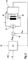
- the microcontroller system 218 in FIG Fig. 2 performs all the control tasks of the braking device and is within ECU 7 ( Fig. 1 ) arranged.
- current source 23 this controls the coil of the solenoid-operated valve 21 at.
- current source 3 the coil current I can be individually set and pulse width modulated for each valve.
- a wire loop or auxiliary coil 22 is provided, whose terminals are connected to measuring device 24.
- the auxiliary coil is arranged to detect the effective magnetic flux through the yoke and armature of the coil.
- Measuring device 24 includes a circuit with which the voltage applied to the measuring coil or wire loop induction voltage U ind can be measured.
- the tap of the induced voltage can also be carried out directly on the valve coil, as shown by dashed lines 26.
- a signal ⁇ is available via the magnetic flux, which is proportional to the integral of the induced voltage U ind (t).
- the signal generated by the tap means 22, 24 over time to determine a magnitude which is proportional to the magnetic flux or the magnetic force. This can then be concluded taking into account the spring force of the valve on the hydraulic force, from which then the differential pressure can be determined on the valve. Taking into account the production-dependent valve properties, the admission pressure for the purpose of regulating the overflow pressure can be measured directly in this way.
Landscapes
- Physics & Mathematics (AREA)
- Engineering & Computer Science (AREA)
- Fluid Mechanics (AREA)
- Electromagnetism (AREA)
- Transportation (AREA)
- Mechanical Engineering (AREA)
- Regulating Braking Force (AREA)
- Magnetically Actuated Valves (AREA)
- Valves And Accessory Devices For Braking Systems (AREA)
Claims (9)
- Procédé pour mesurer la pression d'alimentation au niveau d'une première valve hydraulique analogique à commande électromagnétique (2, 2') pour le réglage fin de la pression dans un circuit de pression (13), dans lequel la pression d'alimentation de la première valve est réglable par l'intermédiaire de la puissance du débit d'un groupe moto-pompe (1, 1'), relié à la première valve par l'intermédiaire d'une conduite de pression (13) du côté sortie de la pompe, une valeur de consigne pour le moteur du groupe moto-pompe étant définie pour la mesure de la pression d'alimentation, notamment dans une installation de freinage hydraulique d'un véhicule automobile, caractérisé en ce que la pression d'alimentation est réglée par le traitement électronique de la réaction des poussoirs de la première valve (2, 2') ou d'une autre valve hydraulique (3, 3') également à commande électromagnétique et reliée à la conduite de pression (13) du côté sortie de la pompe, la réaction des poussoirs étant déterminée au moyen d'un circuit d'asservissement électrique de la position des poussoirs et un signal électrique du circuit d'asservissement électrique de la position des poussoirs participant à la détermination de la valeur de consigne.
- Procédé selon la revendication 1, caractérisé en ce que l'installation de freinage hydraulique comporte plusieurs valves d'entrée (3, 3') et de sortie (4, 4') affectées respectivement aux circuits de pression des roues et en ce que la première valve ou l'autre valve est une valve de séparation (2, 2') à commande analogique pour séparer l'unité d'actionnement des freins (5) des valves d'entrée des circuits de freins des roues.
- Procédé selon la revendication 2, caractérisé en ce que la première valve ou l'autre valve est pourvue d'un dispositif de détection électrique (22, 24) permettant une détermination électronique de la position des poussoirs.
- Procédé selon une au moins des revendications 1 à 3, caractérisé en ce que la position des poussoirs ou la force hydraulique est déterminée au moyen d'un circuit d'asservissement électrique de la position des poussoirs.
- Procédé selon la revendication 3 ou 4, caractérisé en ce que la tension d'induction ou le courant d'induction est déterminé par le dispositif de détection électrique lors d'un déplacement de poussoir, soit par mesure directe sur le bobinage de la valve ou à l'aide d'une boucle ou d'un bobinage de fils supplémentaire dans le périmètre du circuit magnétique de la valve magnétique.
- Procédé selon une au moins des revendications 1 à 5, caractérisé en ce que la première valve ou l'autre valve est réglée par un réglage approprié du courant pour un équilibre des forces ou à son voisinage, de manière à le rendre sensible aux variations de pression.
- Procédé selon une au moins des revendications 1 à 6, caractérisé en ce que la première valve ou l'autre valve est mise à contribution pour la détermination de la pression différentielle appliquée à la valve.
- Procédé selon une au moins des revendications 3 à 7, caractérisé en ce que le signal généré par le dispositif de détection (22, 24) est intégré dans le temps pour déterminer une grandeur proportionnelle au flux magnétique ou à la force magnétique permettant ainsi en tenant compte de la force de ressort de la valve de tirer une conclusion sur la force hydraulique à partir de laquelle on peut alors déterminer la pression différentielle sur la valve.
- Dispositif de régulation à commande électronique de la pression des freins d'un véhicule automobile avec au moins un régulateur ABS, notamment également un régulateur ESP, comprenant un moyen de production de pression (5) permettant d'acheminer des moyens de pression par l'intermédiaire de conduites de pression dans un groupe hydraulique (6) en fonction du désir du conducteur, avec des valves de séparation (2, 2') pour séparer le circuit de pression des roues (A ... D) du moyen de production de pression (5) ainsi que des valves d'entrée (3, 3') qui sont reliées hydrauliquement aux valves de séparation et aux circuits de pression des roues, comprenant de plus des moyens actifs de restauration de la pression (8, 8', 1, 1'), caractérisé en ce que la commande électronique du dispositif est arrangée de telle sorte que celle-ci puisse exécuter si besoin est, un procédé selon au moins une des revendications 1 à 8.
Applications Claiming Priority (2)
| Application Number | Priority Date | Filing Date | Title |
|---|---|---|---|
| DE102007032950A DE102007032950A1 (de) | 2007-07-14 | 2007-07-14 | Verfahren zum Bemessen des Vordrucks an einem analogisierten, elektromagnetisch angesteuerten Hydraulikventil |
| PCT/EP2008/055938 WO2009010319A2 (fr) | 2007-07-14 | 2008-05-15 | Procédé pour mesurer la pression d'alimentation au niveau d'une soupape hydraulique analoguée, à commande électromagnétique |
Publications (2)
| Publication Number | Publication Date |
|---|---|
| EP2170667A2 EP2170667A2 (fr) | 2010-04-07 |
| EP2170667B1 true EP2170667B1 (fr) | 2012-04-25 |
Family
ID=40121544
Family Applications (1)
| Application Number | Title | Priority Date | Filing Date |
|---|---|---|---|
| EP08750294A Not-in-force EP2170667B1 (fr) | 2007-07-14 | 2008-05-15 | Procédé pour mesurer la pression d'alimentation au niveau d'une soupape hydraulique analoguée, à commande électromagnétique |
Country Status (5)
| Country | Link |
|---|---|
| US (1) | US8789897B2 (fr) |
| EP (1) | EP2170667B1 (fr) |
| AT (1) | ATE554979T1 (fr) |
| DE (1) | DE102007032950A1 (fr) |
| WO (1) | WO2009010319A2 (fr) |
Families Citing this family (4)
| Publication number | Priority date | Publication date | Assignee | Title |
|---|---|---|---|---|
| DE102010028083A1 (de) * | 2009-04-23 | 2010-11-11 | Continental Teves Ag & Co. Ohg | Verfahren zur Kalibrierung eines Pumpenmotors in einer Druckregelanlage |
| DE102012224030B4 (de) * | 2012-12-20 | 2025-01-30 | Continental Automotive Technologies GmbH | Verfahren zur beschleunigten Ermittlung eines Korrekturwerts für eine drucksensorlose Bestimmung eines hydraulischen Drucks in einem hydraulischen Bremssystem sowie hydraulisches Bremssystem und Verwendung des Bremssystems |
| DE102015221228A1 (de) * | 2015-01-21 | 2016-07-21 | Continental Teves Ag & Co. Ohg | Bremsensteuervorrichtung für eine hydraulische Kraftfahrzeug-Bremsanlage sowie Bremsanlage |
| CN115493740B (zh) * | 2022-11-14 | 2023-02-28 | 长江勘测规划设计研究有限责任公司 | 利用机器视觉测量水轮机内部流道压力脉动的方法及系统 |
Family Cites Families (23)
| Publication number | Priority date | Publication date | Assignee | Title |
|---|---|---|---|---|
| DE3511975C2 (de) * | 1985-04-02 | 1987-01-22 | Daimler-Benz Ag, 7000 Stuttgart | Hydraulischer Bremskraftverstärker |
| DE3730523A1 (de) * | 1987-09-11 | 1989-03-30 | Bosch Gmbh Robert | Verfahren und einrichtung zur detektion der schaltzeiten von magnetventilen |
| US5628550A (en) * | 1991-10-18 | 1997-05-13 | Itt Automotive Europe Gmbh | Anti-lock hydraulic brake system |
| DE4303206C2 (de) * | 1993-02-04 | 2002-08-08 | Continental Teves Ag & Co Ohg | Verfahren und Schaltungsanordnung zum Bestimmen der Pedalkraft als Regelgröße für eine Bremsanlage mit Blockierschutzregelung |
| DE4438336A1 (de) * | 1994-10-27 | 1996-05-02 | Bosch Gmbh Robert | Magnetventil mit Druckbegrenzung für schlupfgeregelte Kraftfahrzeug-Bremsanlagen |
| DE19508329A1 (de) | 1995-03-09 | 1996-09-12 | Teves Gmbh Alfred | Bremsdruckregelanlage |
| GB9515542D0 (en) * | 1995-07-28 | 1995-09-27 | Lucas Ind Plc | Accumulator pressure control in vehicle brake systems |
| DE19528697A1 (de) * | 1995-08-04 | 1997-02-06 | Bosch Gmbh Robert | Verfahren und Vorrichtung zur Ermittlung einer Druckgröße |
| US6293237B1 (en) * | 1997-12-11 | 2001-09-25 | Diesel Engine Retarders, Inc. | Variable lost motion valve actuator and method |
| DE59913909D1 (de) * | 1998-12-28 | 2006-11-23 | Bosch Gmbh Robert | Verfahren und vorrichtung zur druckermittlung in bremssystemen |
| DE19946777B4 (de) * | 1999-09-29 | 2008-01-10 | Robert Bosch Gmbh | Verfahren und Vorrichtung zur Abschätzung eines Vordrucks bei einer Kraftfahrzeug-Bremsanlage |
| EP1132274B1 (fr) * | 2000-02-26 | 2004-04-07 | WABCO GmbH & CO. OHG | Modulateur de pression de freinage pour système de freinage électronique |
| EP1296865B1 (fr) * | 2000-06-20 | 2004-09-08 | Continental Teves AG & Co. oHG | Procede et systeme asservi de commande d'un systeme de freinage a regulation electronique |
| DE60037967T2 (de) * | 2000-07-01 | 2009-03-26 | Robert Bosch Gmbh | Verfahren und Gerät zur Berechnung der Ansteuerung einer hydraulischen FDR/ESP Unterbaugruppe zur Reduzierung hydraulischer Geräusche |
| WO2003068574A1 (fr) * | 2002-02-14 | 2003-08-21 | Continental Teves Ag & Co. Ohg | Procede pour regler une pression de freinage donnee variable |
| DE10341027A1 (de) | 2002-09-06 | 2004-03-25 | Continental Teves Ag & Co. Ohg | Verfahren und Vorrichtung zur Regelung einer Bremsanlage für Kraftfahrzeuge |
| CA2417074C (fr) * | 2003-01-24 | 2009-07-21 | Pratt & Whitney Canada Corp. | Methode et systeme de detection et d'analyse de tendance |
| WO2005009815A2 (fr) * | 2003-07-31 | 2005-02-03 | Continental Teves Ag & Co. Ohg | Procede pour determiner le courant d'attaque d'un appareil de reglage |
| DE112004001349D2 (de) | 2003-07-31 | 2006-08-31 | Continental Teves Ag & Co Ohg | Verfahren und Vorrichtung zum Messen eines Fluiddrucks mittels eines Stellgeräts |
| US20050067895A1 (en) * | 2003-09-25 | 2005-03-31 | Marathe Sameer S. | Apparatus and method of monitoring braking system pressure |
| US7992947B2 (en) * | 2003-11-26 | 2011-08-09 | Robert Bosch Gmbh | Method for activating a two-stage switching valve |
| DE102005055751C5 (de) * | 2005-04-21 | 2025-04-24 | Ipgate Ag | Druckmodulatorsteuerung |
| DE102005041556A1 (de) | 2005-09-01 | 2007-03-08 | Continental Teves Ag & Co. Ohg | Verfahren zur Bestimmung eines Vordrucks in einer Kraftfahrzeug-Bremsanlage |
-
2007
- 2007-07-14 DE DE102007032950A patent/DE102007032950A1/de not_active Withdrawn
-
2008
- 2008-05-15 AT AT08750294T patent/ATE554979T1/de active
- 2008-05-15 WO PCT/EP2008/055938 patent/WO2009010319A2/fr not_active Ceased
- 2008-05-15 US US12/668,945 patent/US8789897B2/en not_active Expired - Fee Related
- 2008-05-15 EP EP08750294A patent/EP2170667B1/fr not_active Not-in-force
Also Published As
| Publication number | Publication date |
|---|---|
| US20100201184A1 (en) | 2010-08-12 |
| ATE554979T1 (de) | 2012-05-15 |
| US8789897B2 (en) | 2014-07-29 |
| WO2009010319A2 (fr) | 2009-01-22 |
| EP2170667A2 (fr) | 2010-04-07 |
| WO2009010319A3 (fr) | 2009-04-16 |
| DE102007032950A1 (de) | 2009-01-15 |
Similar Documents
| Publication | Publication Date | Title |
|---|---|---|
| EP1876078B1 (fr) | Méthode à déterminer le courant dans un actionneur électrique | |
| EP2238001B1 (fr) | Procédé de conditionnement d'une soupape de régulation | |
| DE19654427B4 (de) | Verfahren und Vorrichtung zur Regelung des Drucks in wenigstens einer Radbremse | |
| EP2822824B1 (fr) | Procede de fonctionnement d'un systeme de freinage de vehicules automobiles, et systeme de freinage | |
| EP1478557B1 (fr) | Procede pour regler une pression de freinage donnee variable | |
| DE102007032949B4 (de) | Verfahren zur Bestimmung der Förderleistung oder der Betätigungshäufigkeit einer Fluidpumpe, insbesondere in einem elektronischen Kraftfahrzeugbremssystem | |
| EP2528789B1 (fr) | Appareil de commande électronique pour un système de freinage | |
| WO2008107219A1 (fr) | Procédé d'étalonnage de soupapes analogisées dans un dispositif de régulation de pression | |
| DE102012205117A1 (de) | Fluiddruckverstärker und diesen aufweisende Fluiddruckbremsvorrichtung | |
| EP2739513B1 (fr) | Procédé d'optimisation de la précision de réglage de la pression | |
| EP2170667B1 (fr) | Procédé pour mesurer la pression d'alimentation au niveau d'une soupape hydraulique analoguée, à commande électromagnétique | |
| DE102008036607A1 (de) | Verfahren und Vorrichtung zur hydraulischen Bremsdruckverstärkung | |
| DE19923689A1 (de) | Elektrohydraulisches Bremssystem und Verfahren zu seiner Steuerung | |
| EP1937529B1 (fr) | Procede pour determiner la pression aux roues dans un systeme de regulation de freinage de vehicule automobile a commande electronique | |
| DE102007018515B4 (de) | Vorrichtung zur Bremsdruckregelung mit Blockierschutzfunktion und weiteren Regelungen | |
| EP1651486B1 (fr) | Procede et dispositif pour mesurer une pression de fluide au moyen d'un organe de regulation | |
| DE102007034113A1 (de) | Verfahren zur Kalibrierung einer Hydraulikpumpe | |
| DE102021211245A1 (de) | Radbremsen Differenzdruckregelung | |
| DE10021436B4 (de) | Verfahren und Einrichtung zum Ermitteln einer Stellgröße eines Ventils und Verfahren und Einrichtung zum Ermitteln einer die Bewegungsgeschwindigkeit eines Aktuators eines Ventils wiedergebenden Größe | |
| DE102009034333B4 (de) | Verfahren zur Beeinflussung des Drehverhaltens einer Fluid-Pumpe in einem Kraftfahrzeugbremssystem | |
| DE102012224030B4 (de) | Verfahren zur beschleunigten Ermittlung eines Korrekturwerts für eine drucksensorlose Bestimmung eines hydraulischen Drucks in einem hydraulischen Bremssystem sowie hydraulisches Bremssystem und Verwendung des Bremssystems | |
| DE102008036216B4 (de) | Druckregelverfahren für Kraftfahrzeugbrems- und Abstandsregelungssysteme | |
| DE102011086737A1 (de) | Verfahren zur Verbesserung einer Vordruckschätzung in einem Hydraulikstrang einer schlupfgeregelten Kraftfahrzeugbremsanlage und Hydraulikstrang einer schlupfgeregelten Kraftfahrzeugbremsanlage | |
| DE102007008908A1 (de) | Kraftfahrzeugbremssystem und Verfahren zur verbesserten ABS-Regelung | |
| DE102008010007A1 (de) | Verfahren und Steuerung zur Erzeugung eines Staudrucks in einer Radbremse |
Legal Events
| Date | Code | Title | Description |
|---|---|---|---|
| PUAI | Public reference made under article 153(3) epc to a published international application that has entered the european phase |
Free format text: ORIGINAL CODE: 0009012 |
|
| 17P | Request for examination filed |
Effective date: 20100215 |
|
| AK | Designated contracting states |
Kind code of ref document: A2 Designated state(s): AT BE BG CH CY CZ DE DK EE ES FI FR GB GR HR HU IE IS IT LI LT LU LV MC MT NL NO PL PT RO SE SI SK TR |
|
| 17Q | First examination report despatched |
Effective date: 20110429 |
|
| GRAP | Despatch of communication of intention to grant a patent |
Free format text: ORIGINAL CODE: EPIDOSNIGR1 |
|
| GRAC | Information related to communication of intention to grant a patent modified |
Free format text: ORIGINAL CODE: EPIDOSCIGR1 |
|
| DAX | Request for extension of the european patent (deleted) | ||
| RAP1 | Party data changed (applicant data changed or rights of an application transferred) |
Owner name: CONTINENTAL TEVES AG & CO. OHG |
|
| GRAS | Grant fee paid |
Free format text: ORIGINAL CODE: EPIDOSNIGR3 |
|
| GRAA | (expected) grant |
Free format text: ORIGINAL CODE: 0009210 |
|
| AK | Designated contracting states |
Kind code of ref document: B1 Designated state(s): AT BE BG CH CY CZ DE DK EE ES FI FR GB GR HR HU IE IS IT LI LT LU LV MC MT NL NO PL PT RO SE SI SK TR |
|
| REG | Reference to a national code |
Ref country code: GB Ref legal event code: FG4D Free format text: NOT ENGLISH |
|
| REG | Reference to a national code |
Ref country code: CH Ref legal event code: EP |
|
| REG | Reference to a national code |
Ref country code: AT Ref legal event code: REF Ref document number: 554979 Country of ref document: AT Kind code of ref document: T Effective date: 20120515 |
|
| REG | Reference to a national code |
Ref country code: IE Ref legal event code: FG4D Free format text: LANGUAGE OF EP DOCUMENT: GERMAN |
|
| REG | Reference to a national code |
Ref country code: DE Ref legal event code: R096 Ref document number: 502008007062 Country of ref document: DE Effective date: 20120621 |
|
| REG | Reference to a national code |
Ref country code: NL Ref legal event code: VDEP Effective date: 20120425 |
|
| LTIE | Lt: invalidation of european patent or patent extension |
Effective date: 20120425 |
|
| PG25 | Lapsed in a contracting state [announced via postgrant information from national office to epo] |
Ref country code: PL Free format text: LAPSE BECAUSE OF FAILURE TO SUBMIT A TRANSLATION OF THE DESCRIPTION OR TO PAY THE FEE WITHIN THE PRESCRIBED TIME-LIMIT Effective date: 20120425 Ref country code: IS Free format text: LAPSE BECAUSE OF FAILURE TO SUBMIT A TRANSLATION OF THE DESCRIPTION OR TO PAY THE FEE WITHIN THE PRESCRIBED TIME-LIMIT Effective date: 20120825 Ref country code: NO Free format text: LAPSE BECAUSE OF FAILURE TO SUBMIT A TRANSLATION OF THE DESCRIPTION OR TO PAY THE FEE WITHIN THE PRESCRIBED TIME-LIMIT Effective date: 20120725 Ref country code: FI Free format text: LAPSE BECAUSE OF FAILURE TO SUBMIT A TRANSLATION OF THE DESCRIPTION OR TO PAY THE FEE WITHIN THE PRESCRIBED TIME-LIMIT Effective date: 20120425 Ref country code: LT Free format text: LAPSE BECAUSE OF FAILURE TO SUBMIT A TRANSLATION OF THE DESCRIPTION OR TO PAY THE FEE WITHIN THE PRESCRIBED TIME-LIMIT Effective date: 20120425 Ref country code: CY Free format text: LAPSE BECAUSE OF FAILURE TO SUBMIT A TRANSLATION OF THE DESCRIPTION OR TO PAY THE FEE WITHIN THE PRESCRIBED TIME-LIMIT Effective date: 20120425 Ref country code: SE Free format text: LAPSE BECAUSE OF FAILURE TO SUBMIT A TRANSLATION OF THE DESCRIPTION OR TO PAY THE FEE WITHIN THE PRESCRIBED TIME-LIMIT Effective date: 20120425 |
|
| BERE | Be: lapsed |
Owner name: CONTINENTAL TEVES A.G. & CO. OHG Effective date: 20120531 |
|
| PG25 | Lapsed in a contracting state [announced via postgrant information from national office to epo] |
Ref country code: HR Free format text: LAPSE BECAUSE OF FAILURE TO SUBMIT A TRANSLATION OF THE DESCRIPTION OR TO PAY THE FEE WITHIN THE PRESCRIBED TIME-LIMIT Effective date: 20120425 Ref country code: SI Free format text: LAPSE BECAUSE OF FAILURE TO SUBMIT A TRANSLATION OF THE DESCRIPTION OR TO PAY THE FEE WITHIN THE PRESCRIBED TIME-LIMIT Effective date: 20120425 Ref country code: PT Free format text: LAPSE BECAUSE OF FAILURE TO SUBMIT A TRANSLATION OF THE DESCRIPTION OR TO PAY THE FEE WITHIN THE PRESCRIBED TIME-LIMIT Effective date: 20120827 Ref country code: GR Free format text: LAPSE BECAUSE OF FAILURE TO SUBMIT A TRANSLATION OF THE DESCRIPTION OR TO PAY THE FEE WITHIN THE PRESCRIBED TIME-LIMIT Effective date: 20120726 Ref country code: LV Free format text: LAPSE BECAUSE OF FAILURE TO SUBMIT A TRANSLATION OF THE DESCRIPTION OR TO PAY THE FEE WITHIN THE PRESCRIBED TIME-LIMIT Effective date: 20120425 |
|
| PG25 | Lapsed in a contracting state [announced via postgrant information from national office to epo] |
Ref country code: MC Free format text: LAPSE BECAUSE OF NON-PAYMENT OF DUE FEES Effective date: 20120531 |
|
| REG | Reference to a national code |
Ref country code: CH Ref legal event code: PL |
|
| PG25 | Lapsed in a contracting state [announced via postgrant information from national office to epo] |
Ref country code: CZ Free format text: LAPSE BECAUSE OF FAILURE TO SUBMIT A TRANSLATION OF THE DESCRIPTION OR TO PAY THE FEE WITHIN THE PRESCRIBED TIME-LIMIT Effective date: 20120425 Ref country code: SK Free format text: LAPSE BECAUSE OF FAILURE TO SUBMIT A TRANSLATION OF THE DESCRIPTION OR TO PAY THE FEE WITHIN THE PRESCRIBED TIME-LIMIT Effective date: 20120425 Ref country code: CH Free format text: LAPSE BECAUSE OF NON-PAYMENT OF DUE FEES Effective date: 20120531 Ref country code: DK Free format text: LAPSE BECAUSE OF FAILURE TO SUBMIT A TRANSLATION OF THE DESCRIPTION OR TO PAY THE FEE WITHIN THE PRESCRIBED TIME-LIMIT Effective date: 20120425 Ref country code: RO Free format text: LAPSE BECAUSE OF FAILURE TO SUBMIT A TRANSLATION OF THE DESCRIPTION OR TO PAY THE FEE WITHIN THE PRESCRIBED TIME-LIMIT Effective date: 20120425 Ref country code: LI Free format text: LAPSE BECAUSE OF NON-PAYMENT OF DUE FEES Effective date: 20120531 Ref country code: NL Free format text: LAPSE BECAUSE OF FAILURE TO SUBMIT A TRANSLATION OF THE DESCRIPTION OR TO PAY THE FEE WITHIN THE PRESCRIBED TIME-LIMIT Effective date: 20120425 Ref country code: EE Free format text: LAPSE BECAUSE OF FAILURE TO SUBMIT A TRANSLATION OF THE DESCRIPTION OR TO PAY THE FEE WITHIN THE PRESCRIBED TIME-LIMIT Effective date: 20120425 |
|
| REG | Reference to a national code |
Ref country code: IE Ref legal event code: MM4A |
|
| PG25 | Lapsed in a contracting state [announced via postgrant information from national office to epo] |
Ref country code: IT Free format text: LAPSE BECAUSE OF FAILURE TO SUBMIT A TRANSLATION OF THE DESCRIPTION OR TO PAY THE FEE WITHIN THE PRESCRIBED TIME-LIMIT Effective date: 20120425 Ref country code: BE Free format text: LAPSE BECAUSE OF NON-PAYMENT OF DUE FEES Effective date: 20120531 |
|
| PLBE | No opposition filed within time limit |
Free format text: ORIGINAL CODE: 0009261 |
|
| REG | Reference to a national code |
Ref country code: FR Ref legal event code: ST Effective date: 20130131 |
|
| STAA | Information on the status of an ep patent application or granted ep patent |
Free format text: STATUS: NO OPPOSITION FILED WITHIN TIME LIMIT |
|
| GBPC | Gb: european patent ceased through non-payment of renewal fee |
Effective date: 20120725 |
|
| 26N | No opposition filed |
Effective date: 20130128 |
|
| PG25 | Lapsed in a contracting state [announced via postgrant information from national office to epo] |
Ref country code: IE Free format text: LAPSE BECAUSE OF NON-PAYMENT OF DUE FEES Effective date: 20120515 Ref country code: ES Free format text: LAPSE BECAUSE OF FAILURE TO SUBMIT A TRANSLATION OF THE DESCRIPTION OR TO PAY THE FEE WITHIN THE PRESCRIBED TIME-LIMIT Effective date: 20120805 Ref country code: GB Free format text: LAPSE BECAUSE OF NON-PAYMENT OF DUE FEES Effective date: 20120725 Ref country code: FR Free format text: LAPSE BECAUSE OF NON-PAYMENT OF DUE FEES Effective date: 20120625 |
|
| REG | Reference to a national code |
Ref country code: DE Ref legal event code: R097 Ref document number: 502008007062 Country of ref document: DE Effective date: 20130128 |
|
| PG25 | Lapsed in a contracting state [announced via postgrant information from national office to epo] |
Ref country code: BG Free format text: LAPSE BECAUSE OF FAILURE TO SUBMIT A TRANSLATION OF THE DESCRIPTION OR TO PAY THE FEE WITHIN THE PRESCRIBED TIME-LIMIT Effective date: 20120725 Ref country code: MT Free format text: LAPSE BECAUSE OF FAILURE TO SUBMIT A TRANSLATION OF THE DESCRIPTION OR TO PAY THE FEE WITHIN THE PRESCRIBED TIME-LIMIT Effective date: 20120425 |
|
| PG25 | Lapsed in a contracting state [announced via postgrant information from national office to epo] |
Ref country code: TR Free format text: LAPSE BECAUSE OF FAILURE TO SUBMIT A TRANSLATION OF THE DESCRIPTION OR TO PAY THE FEE WITHIN THE PRESCRIBED TIME-LIMIT Effective date: 20120425 |
|
| PG25 | Lapsed in a contracting state [announced via postgrant information from national office to epo] |
Ref country code: LU Free format text: LAPSE BECAUSE OF NON-PAYMENT OF DUE FEES Effective date: 20120515 |
|
| REG | Reference to a national code |
Ref country code: AT Ref legal event code: MM01 Ref document number: 554979 Country of ref document: AT Kind code of ref document: T Effective date: 20130515 |
|
| PG25 | Lapsed in a contracting state [announced via postgrant information from national office to epo] |
Ref country code: HU Free format text: LAPSE BECAUSE OF FAILURE TO SUBMIT A TRANSLATION OF THE DESCRIPTION OR TO PAY THE FEE WITHIN THE PRESCRIBED TIME-LIMIT Effective date: 20080515 |
|
| PG25 | Lapsed in a contracting state [announced via postgrant information from national office to epo] |
Ref country code: AT Free format text: LAPSE BECAUSE OF NON-PAYMENT OF DUE FEES Effective date: 20130515 |
|
| REG | Reference to a national code |
Ref country code: DE Ref legal event code: R084 Ref document number: 502008007062 Country of ref document: DE |
|
| PGFP | Annual fee paid to national office [announced via postgrant information from national office to epo] |
Ref country code: DE Payment date: 20200531 Year of fee payment: 13 |
|
| REG | Reference to a national code |
Ref country code: DE Ref legal event code: R119 Ref document number: 502008007062 Country of ref document: DE |
|
| PG25 | Lapsed in a contracting state [announced via postgrant information from national office to epo] |
Ref country code: DE Free format text: LAPSE BECAUSE OF NON-PAYMENT OF DUE FEES Effective date: 20211201 |