EP2172144A2 - Geschirrkorb - Google Patents
Geschirrkorb Download PDFInfo
- Publication number
- EP2172144A2 EP2172144A2 EP09011806A EP09011806A EP2172144A2 EP 2172144 A2 EP2172144 A2 EP 2172144A2 EP 09011806 A EP09011806 A EP 09011806A EP 09011806 A EP09011806 A EP 09011806A EP 2172144 A2 EP2172144 A2 EP 2172144A2
- Authority
- EP
- European Patent Office
- Prior art keywords
- supports
- plate
- basket
- dish rack
- basket bottom
- Prior art date
- Legal status (The legal status is an assumption and is not a legal conclusion. Google has not performed a legal analysis and makes no representation as to the accuracy of the status listed.)
- Granted
Links
Images


Classifications
-
- A—HUMAN NECESSITIES
- A47—FURNITURE; DOMESTIC ARTICLES OR APPLIANCES; COFFEE MILLS; SPICE MILLS; SUCTION CLEANERS IN GENERAL
- A47L—DOMESTIC WASHING OR CLEANING; SUCTION CLEANERS IN GENERAL
- A47L15/00—Washing or rinsing machines for crockery or tableware
- A47L15/42—Details
- A47L15/50—Racks ; Baskets
- A47L15/501—Baskets, e.g. for conveyor-type, in-sink type or hood-type machines
-
- A—HUMAN NECESSITIES
- A47—FURNITURE; DOMESTIC ARTICLES OR APPLIANCES; COFFEE MILLS; SPICE MILLS; SUCTION CLEANERS IN GENERAL
- A47L—DOMESTIC WASHING OR CLEANING; SUCTION CLEANERS IN GENERAL
- A47L19/00—Drying devices for crockery or table-ware, e.g. tea-cloths
- A47L19/04—Crockery baskets; Draining-racks
Definitions
- the present invention relates to a crockery basket with at least one basket bottom and integrally formed on the bottom of the basket supports for leaning a plate underside of a dish mounted in the dish rack plate on the supports, at least two, spaced from each other arranged in the dish rack columns form a pair of columns for leaning the bottom plate ,
- Baskets are used in the prior art, on the one hand for storing, on the other hand, but also for washing dishes in special designed for the catering dishwashers.
- the baskets have a basket base provided with a passage opening so that moisture still left on the dishes can leave the basket.
- the known in the prior art baskets are stackable.
- Crockery baskets for plates are designed so that plates on the edge of their plates are ajar against supports so as to ensure optimum accessibility to all surfaces of the plates during the rinsing process.
- there are generic crockery baskets in which the supports in the form of e.g. wire-shaped inserts are executed.
- the supports are, however, formed on the basket bottom.
- the object of the invention is therefore to improve generic dish baskets to the effect that as many plates of different sizes can be safely stored standing on the edge of their plate in the dish rack, without the risk that these plates strike each other.
- the supports of the pair of supports on their side facing away from the basket bottom each have a bevelled support edge for leaning against the bottom of the plate, wherein the bevelled support edges of these two supports are tapered sloping each toward each other in the direction towards the basket bottom.
- each in the direction of each other sloping bevelled support edges of each support pair forming pillars it is possible to support very different sized plate standing on its plate edge. Due to the beveled support edges can be guaranteed as high as possible upright position for both the very large, as well as for the very small plate, which is on the one hand for rinsing the plate low and on the other hand, a relatively tight packing of the plate in the dish rack and thus a high Number of plates per crockery basket allows.
- the supporting edges need not necessarily be designed in the form of acute-angled edges in the mathematical sense. Rather, they can also be rounded and / or flat in the form of support surfaces. They generally designate the portion of the surface of the respective support provided for leaning on the underside of the plate of the plate-shaped plate.
- the term "slanted” generally means arrangements that are neither parallel nor orthogonal. These terms thus include all those angles that deviate from 0 ° and 90 ° and the integer multiples of 90 °. Under a standing storage of the plate in the dish rack is understood that the plate stand in the dish rack or on the basket bottom of the dish rack on their plate edge.
- the plates are not strictly orthogonal freestanding, but supported more or less obliquely against the vertical with the bottom of the plate on the supports.
- Under the underside of the plate is understood the outer surface of the plate, which is the normal food from the plate of the pad on which the plate is facing. On the opposite top of the plate is the food.
- the edge of the plate is the edge or the edge of the plate, the (underside of) plate underside and plate top separate from each other.
- the "operating position of the crockery basket" that position is understood in which the crockery basket stands with his basket bottom on a generally horizontal surface. In this position, it can be loaded from above with plates or trays.
- the plates can of course also be leaned against the supports or their supporting edges with their top of the plate.
- An optimal space utilization of the baskets according to the invention results when the plates are leaned against the supports with their plate underside or the area of the plate edge facing the underside of the plate.
- a support pair of at least two supports As a rule, these are exactly two supports per pair of supports. But it can also be provided additional supports for a plate, if this makes sense in a specific embodiment appears.
- the crockery basket usually has a plurality of pairs of supports.
- the term "molded" is understood to mean a one-piece attachment or connection.
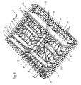
- Fig. 1 is an example to see how different sized plates 6 are stored standing in the dish rack 1 on its plate edge 5.
- each plate 6 is assigned a parking space within the dish rack 1.
- This parking space is defined on the one hand by two supports 3 forming a pair of supports and the additional supports 14 assigned to this pair of supports.
- the plates 6 are supported on their undersides 4 of the beveled support edges 7 of the supports 3.
- the bottom plate 4 is also the, the bottom of the plate 4 facing area of the plate edge 5 attributed, with, as with the small plate in Fig.1 to see, especially small plates lean against the supporting edges 7.
- the additional support edges 15 of the additional supports 14 prevent slipping of the plate from their standing positions by the plate edge 5 partially applied to the additional support edges 15.
- the additional support edges 15 need not necessarily be designed in the form of acute-angled edges in the mathematical sense. They too can be rounded and / or flat in the form of additional supporting surfaces. They generally designate the area or location of the surface of the respective additional support 14 which is provided for supporting the rim 5 of the plate 6.
- the shown embodiment of a crockery basket 1 has two rows 17 and 17 'of pairs of supports.
- the support pairs are arranged one behind the other within the respective row 17, 17 ', so that a total of two rows of plates can be arranged in the dish rack 1, adjacent to one another.
- special arrangement of the two rows 17 and 17 'relative to each other it is possible that even larger trays 24, which extend over both rows, can be arranged standing in the dish rack 1.
- the supports of a pair of supports in the illustrated embodiment slightly obliquely opposite the side walls 12 of the dish rack 1 arranged.
- the two rows 17 and 17 ' have an offset 18 which allows, as in Fig. 1 shown to place two extra-large plates 6 adjacent to each other in each one of the rows 17 and 17 ', without the plates abutting one another. This is made possible in particular by the offset 18 of the two rows 17 and 17 'to one another.
- the supports 4 and in the embodiment shown, the additional supports 14 are integrally formed on the basket bottom 2, or integrally connected thereto. They stand like free-standing piles or posts or posts from the basket bottom 2.
- the dish rack 1 of the embodiment shown here is formed substantially square in its basic form. This is a common in the prior art basic form. Of course, it can also be deviated from.
- the outer edge length of the dish rack 1 is approximately 60 cm in the illustrated embodiment.
- the two supports 3 of each pair of supports are each at least partially, here completely, plate-shaped.
- the beveled support edges 7 each form the technological of the basket bottom 2 boundary of these plate-shaped areas.
- the bevelled support edges 7 fall in the respective direction 8 towards each other, in the direction 9 towards the basket bottom 2 from.
- ribs 11 can be arranged to reinforce or support the supports 3 on the basket bottom 2.
- these are integrally formed on the respective support 3 and / or the basket bottom 2.
- the surfaces of the plate-shaped areas of the two supports 3 of a pair of supports are conveniently located in a common plane.
- the ribs 11 are advantageously arranged obliquely or orthogonally to this common plane.
- the common level is described below by means of Fig. 3 explained in more detail.
- a support pair of supports 3 are each associated with two additional supports 14, at the additional support edges 15 of the basket bottom 2 facing portion of the plate rim 5 can be supported. This does not necessarily have to be this way. Deviating from this, it can also be provided that only one or more than two additional supports 14 are assigned to the respective pair of supports. If it is two or more additional supports 14 per pitch or support pair, the additional supports 14 are conveniently spaced from each other. In the basket bottom 2 are conveniently provided for receiving the plate edge 5 of each plate 6 between the two each pair of supports associated additional supports 14 wells. In the embodiment shown, this is realized in that the basket bottom 2 is already formed lattice-like and the bars provide a corresponding space for the recess.
- lattice-shaped or perforated embodiments of the basket bottom 2 and side walls 12 of the dish rack 1 are favorable to to ensure a quick drying of the dishes and to ensure that no residual moisture remains in the basket.
- weight and weight are of course saved by the recess or the lattice-like training.
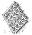
- Fig. 2 shows again a perspective view in the form of a view obliquely from above on the crockery basket 1, in which no plates 6 or trays 24 in the crockery basket 1 are present. It can also be seen here that the upper edges of the side walls 12, which are adjacent to the respective outer supports 3, are slightly lowered so that the plate edges 5 of large plates 6 can still project beyond them.
- Fig. 3 It is a top view of the basket bottom 2. It is a view along a vertical from top to bottom on the rising on a horizontal surface dish rack 1. In this view, some particularly preferred design features of a dish rack according to the invention 1 can be seen particularly well.
- the bevelled support edges 7 of the two supports 3 of a pair of supports lie in the plan view shown on the basket bottom 2 on a common straight line 10.
- a vertical plane which forms a common plane in which the support edges 7 of the two supports 3 of the pair of supports.
- this common plane is also in each case a surface of the plate-shaped areas of the two supports 3 of this pair of supports.
- the opposite surfaces of the plate-shaped areas of the two supports 3 of the pair of supports lie in a common plane parallel thereto. Also good to see in this illustration according to Fig.
- an oblique angle 13 is provided, which is preferably in the angular range of 70 ° to 89 °. In the embodiment shown is an angle 13 between 86 ° and 87 °.
- top view of the basket bottom 2 are also the additional support edges 15 of the support pair associated additional supports 14 on a common line. This is referred to here as the second common line 16. It runs parallel to the common straight line 10 of the supporting edges 7 of the associated support pair.
- both the common straight lines 10 of the respective pairs of supports within the rows 17 and 17 ' run parallel to one another, and the common straight lines 10 of the row 17 parallel to the corresponding common straight lines 10' of the support edges 7 of the pairs of supports of the second row 17 '.
- an offset 18 between the common lines 10 is favorably to enable overlapping of large plates 6 shown one row 17 and the common line 10 'of the adjacent other row 17'.
- the offset 18 is in each case the smallest distance between the respectively adjacent common straight lines 10 and 10 ', as shown in FIG Fig. 3 is also marked.
- Fig. 1 On the one hand to allow the most dense packing of plates 6 and on the other hand, but also the insertion of larger trays 24, as in Fig. 1 is shown to allow in both rows 17 and 17 ', it is conveniently provided that the offset 18 between the common line 10 of a row 17 and the common line 10' of the adjacent row 17 'smaller than half of the distance 19 between the common line 10 of two within a row 17 or 17 'directly behind one another arranged pairs of supports.
- the distance 19 between two common lines 10 of in a row 17 successively arranged pairs of supports is conveniently from 30mm to 80mm.
- both the deviating from the orthogonal angle 13 of the common line 10 and 10 'and their offset 18 are provided to each other. This does not necessarily have to be this way.
- the angle 13 may also correspond to the orthogonal, but then in this embodiment, the provision of an offset 18 is useful.
- Fig. 3 are also the distances 20 and 21 located between the supports 3 of a pair of supports.
- the distance 20 between the, the basket bottom 2 facing ends of the bevelled support edges 7 is conveniently between 10 cm and 16 cm.
- the distance 21 between the ends facing away from the basket bottom edges of the chamfered support edges 7 of the supports 3 of the respective pair of supports is conveniently between 16 cm and 26 cm.
- Fig. 4 shows a side view obliquely from above on the dish rack 1.
- the distances 22 and 23 of the chamfered supporting edges 7 from the basket bottom 2 located.
- the distance 23 between the, the basket bottom 2 facing the end of the chamfered support edge 7 and the basket bottom is conveniently from 0 cm to 8 cm.
- the distance 22 between the, away from the basket bottom 2 end of the tapered support edge 7 and the basket bottom 2 is conveniently from 5 cm to 10 cm.
- the additional supports 14 are favorably designed significantly shorter than the supports 3. They extend beyond the basket bottom 2 in a direction normal to the basket bottom 2 conveniently between 1 cm and 6 cm.
- Fig. 5 shows a view from below of the basket bottom 2 of the dish rack. 1
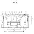
- Fig. 6 shows once again a vertical section along a common plane or one of the common lines 10 and 10 'through the supports 3 of a pair of columns.
- the different distances 20, 21, 22 and 23 are shown again as an illustration, as well as the directions 8 and 9. Especially good to see is in this representation
- the beveled support edges 7 when in an operative position on a horizontal surface set crockery 1, the beveled support edges 7 with a horizontal plane 25 an angle 26 in an angular range of 20 ° to 70 °, preferably between 40 ° and 60 °, here 50 °.
- the support edges 7 can, as shown here, run linear. But there are also other, e.g. curved courses of the supporting edges 7 conceivable.
- Preferred embodiments of crockery baskets 1 according to the invention provide that the supports 3 and / or the basket bottom 2 and / or the additional supports 14 and particularly preferably in particular the entire crockery basket 1, preferably in one piece, consist of plastic. It can be used for the crockery baskets 1 used in the prior art, such as polyethylene, polypropylene, etc., also for inventive baskets 1 used.
- the illustrated embodiment of a dish rack 1 can be used for plates with a diameter of 8 cm to plates with a diameter of 34 cm.
Landscapes
- Washing And Drying Of Tableware (AREA)
- Warehouses Or Storage Devices (AREA)
- Packaging Of Annular Or Rod-Shaped Articles, Wearing Apparel, Cassettes, Or The Like (AREA)
- Rigid Containers With Two Or More Constituent Elements (AREA)
Abstract
Description
- Die vorliegende Erfindung betrifft einen Geschirrkorb mit zumindest einem Korbboden und mit am Korbboden angeformten Stützen zum Anlehnen einer Tellerunterseite eines auf einem Tellerrand stehend im Geschirrkorb gelagerten Tellers an den Stützen, wobei zumindest zwei, voneinander beabstandet im Geschirrkorb angeordnete Stützen ein Stützenpaar zum Anlehnen der Tellerunterseite bilden.
- Geschirrkörbe werden beim Stand der Technik einerseits zum Lagern, andererseits aber auch zum Spülen von Geschirr in speziellen für die Gastronomie ausgelegten Geschirrspülmaschinen verwendet. Die Geschirrkörbe haben in der Regel einen mit Durchtrittsöffnung versehenen Korbboden, damit noch am Geschirr vorhandene Feuchtigkeit den Korb verlassen kann. In der Regel sind die beim Stand der Technik bekannten Geschirrkörbe stapelbar. Es gibt verschiedenste Einsätze um verschiedene Arten von Geschirr sicher in Position im Geschirrkorb zu halten. Geschirrkörbe für Teller sind dazu ausgelegt, dass Teller auf ihrem Tellerrand stehend an Stützen angelehnt werden, um so eine optimale Zugänglichkeit auf alle Flächen der Teller während des Spülvorgangs zu gewährleisten. Beim Stand der Technik gibt es gattungsfremde Geschirrkörbe, bei denen die Stützen in Form von z.B. drahtförmigen Einsätzen ausgeführt sind. Bei gattungsgemäßen Geschirrkörben der oben genannten Art sind die Stützen jedoch an den Korbboden angeformt.
- Insbesondere in der Gastronomie hat sich in den letzten Jahren immer mehr der Trend zur Verwendung von besonders großen Tellern durchgesetzt. Dies stellt die Gastronomie vor das Problem, dass nun verschiedenste Teller mit verschiedensten Größen gelagert und auch gespült werden müssen. Nun ist es zwar denkbar, für jede Tellergröße einen eigenen, speziell angepassten Geschirrkorb vorzusehen. Dies ist aber unwirtschaftlich und auch unpraktisch im täglichen Betrieb.
- Aufgabe der Erfindung ist es daher, gattungsgemäße Geschirrkörbe dahingehend zu verbessern, dass im Geschirrkorb möglichst viele Teller unterschiedlicher Größe sicher auf ihrem Tellerrand stehend gelagert werden können, ohne dass die Gefahr besteht, dass diese Teller aneinander anschlagen.
- Dies wird erfindungsgemäß erreicht, indem die Stützen des Stützenpaares auf ihrer vom Korbboden abgewandten Seite jeweils eine abgeschrägte Stützkante zum daran Anlehnen der Tellerunterseite aufweisen, wobei die abgeschrägten Stützkanten dieser beiden Stützen jeweils in Richtung aufeinander zu, in Richtung hin zum Korbboden abfallend abgeschrägt sind.
- Durch die jeweils in Richtung aufeinander zu abfallend abgeschrägten Stützkanten der jeweils ein Stützenpaar bildenden Stützen, ist es möglich, sehr unterschiedlich große Teller auf ihrem Tellerrand stehend abzustützen. Durch die abgeschrägten Stützkanten kann sowohl für die sehr großen, als auch für die sehr kleinen Teller eine möglichst aufrechte Standposition gewährleistet werden, was zum Einen zum Spülen der Teller günstig ist und zum Anderen auch eine relativ dichte Packung der Teller im Geschirrkorb und damit eine hohe Anzahl von Tellern pro Geschirrkorb ermöglicht.
- Die Stützkanten müssen nicht zwingend in Form von spitzwinkeligen Kanten im mathematischen Sinn ausgebildet sein. Sie können vielmehr auch abgerundet und/oder auch flächig in Form von Stützflächen ausgebildet sein. Sie bezeichnen allgemein den Bereich bzw. Abschnitt der Oberfläche der jeweiligen Stütze, der für das Anlehnen der Tellerunterseite des auf dem Tellerrand stehenden Tellers vorgesehen ist. Der Begriff "schräg" bzw. "abgeschrägt" steht allgemein für Anordnungen die weder parallel noch orthogonal sind. Diese Begriffe umfassen somit all diejenigen Winkel, die von 0° und 90° und den ganzzahligen Vielfachen von 90° abweichen. Unter einer stehenden Lagerung der Teller im Geschirrkorb wird verstanden, dass die Teller im Geschirrkorb bzw. auf dem Korbboden des Geschirrkorbes auf ihrem Tellerrand stehen. Dabei sind die Teller jedoch nicht streng orthogonal freistehend, sondern mehr oder weniger schräg gegen die Vertikale mit der Tellerunterseite an den Stützen abgestützt. Unter der Tellerunterseite wird die äußere Oberfläche des Tellers verstanden, die beim normalen Essen aus dem Teller der Unterlage, auf dem der Teller steht, zugewandt ist. Auf der gegenüberliegenden Telleroberseite befindet sich das Essen. Der Tellerrand ist die Kante bzw. der Rand des Tellers, die (der) Tellerunterseite und Telleroberseite voneinander trennen. Unter dem weiter unten verwendeten Begriff der "Betriebsstellung des Geschirrkorbes" wird diejenige Stellung verstanden, in der der Geschirrkorb mit seinem Korbboden auf einer in der Regel horizontalen Fläche steht. In dieser Stellung kann er von oben mit Tellern oder Tabletts beladen werden. Der Vollständigkeit halber wird darauf hingewiesen, dass die Teller natürlich auch mit ihrer Telleroberseite an den Stützen bzw. deren Stützkanten angelehnt werden können. Eine optimale Platzausnutzung der erfindungsgemäßen Geschirrkörbe ergibt sich aber, wenn die Teller mit ihrer Tellerunterseite bzw. dem der Tellerunterseite zugewandten Bereich des Tellerrandes an den Stützen angelehnt werden. Zum Anlehnen eines Tellers ist immer ein Stützenpaar aus zumindest zwei Stützen vorgesehen. In der Regel handelt es sich dabei um genau zwei Stützen pro Stützenpaar. Es können aber auch noch zusätzliche Stützen für einen Teller vorgesehen sein, wenn dies in einer speziellen Ausführungsform sinnvoll erscheint. Der Geschirrkorb weist in der Regel eine Vielzahl von Stützenpaaren auf. Unter dem Begriff "angeformt" wird eine einstückige Befestigung bzw. Verbindung verstanden.
- Weitere Einzelheiten und Merkmale eines bevorzugten Ausführungsbeispiels der Erfindung werden anhand der nachfolgenden Figurenbeschreibung erläutert. Dabei zeigen:
-
Fig. 1 eine perspektivische Ansicht auf das erfindungsgemäße Ausführungsbeispiel eines Geschirrkorbes;, wobei verschieden große Teller und ein Tablett im Geschirrkorb stehend gelagert sind; -
Fig. 2 eine perspektivische Ansicht auf diesen Geschirrkorb, ohne Teller und ohne Tablett; -
Fig. 3 eine Draufsicht auf den Geschirrkorb, bzw. dessen Korbboden; -
Fig. 4 eine weitere perspektivische Ansicht des Geschirrkorbes; -
Fig. 5 eine perspektivische Ansicht auf die Unterseite des Geschirrkorbes; -
Fig. 6 eine Detaildarstellung als Schnitt entlang der gemeinsamen Ebene der beiden Stützen eines Stützenpaares. - In
Fig. 1 ist beispielhaft zu sehen, wie verschieden große Teller 6 in dem Geschirrkorb 1 auf ihrem Tellerrand 5 stehend gelagert sind. Um sie in dieser Position zu halten, ist jedem Teller 6 ein Stellplatz innerhalb des Geschirrkorbes 1 zugewiesen. Dieser Stellplatz ist einerseits durch zwei, ein Stützenpaar bildende Stützen 3 und die diesem Stützenpaar zugeordneten Zusatzstützen 14 vorgegeben. Die Teller 6 werden an ihren Tellerunterseiten 4 von den abgeschrägten Stützkanten 7 der Stützen 3 abgestützt. In diesem Sinne ist der Tellerunterseite 4 auch der, der Tellerunterseite 4 zugewandte Bereich des Tellerrandes 5 zuzurechnen, mit dem, wie beim kleinen Teller inFig.1 zu sehen, sich vor allem kleine Teller an den Stützkanten 7 anlehnen. Die Zusatzstützkanten 15 der Zusatzstützen 14 verhindern ein Abrutschen der Teller aus ihren stehenden Positionen, indem der Tellerrand 5 bereichsweise an den Zusatzstützkanten 15 anliegt. Auch die Zusatzstützkanten 15 müssen nicht zwingend in Form von spitzwinkeligen Kanten im mathematischen Sinn ausgebildet sein. Auch sie können abgerundet und/oder auch flächig in Form von Zusatzstützflächen ausgebildet sein. Sie bezeichnen allgemein den Bereich bzw. die Stelle der Oberfläche der jeweiligen Zusatzstütze 14, der (die) für das Abstützen des Tellerrandes 5 des Tellers 6 vorgesehen ist. - Die gezeigte Ausgestaltungsform eines erfindungsgemäßen Geschirrkorbes 1 weist zwei Reihen 17 und 17' von Stützenpaaren auf. Die Stützenpaare sind innerhalb der jeweiligen Reihe 17, 17' hintereinander angeordnet, sodass insgesamt im Geschirrkorb 1, benachbart zueinander, zwei Reihen von Tellern angeordnet werden können. Durch die weiter unten im Detail erläuterte spezielle Anordnung der beiden Reihen 17 und 17' relativ zueinander, ist es möglich, dass auch größere Tabletts 24, welche sich über beide Reihen erstrecken, im Geschirrkorb 1 stehend angeordnet werden können. Wie weiter unten anhand von
Fig. 3 im Detail noch erläutert, sind die Stützen eines Stützenpaares im gezeigten Ausführungsbeispiel leicht schräg gegenüber den Seitenwänden 12 des Geschirrkorbes 1 angeordnet. Darüber hinaus haben die beiden Reihen 17 und 17' einen Versatz 18, welcher es erlaubt, wie inFig. 1 dargestellt, zwei besonders große Teller 6 benachbart zueinander in jeweils eine der Reihen 17 und 17' zu stellen, ohne dass die Teller aneinander anschlagen. Dies wird insbesondere durch den Versatz 18 der beiden Reihen 17 und 17' zueinander ermöglicht. - Die Stützen 4 und im gezeigten Ausführungsbeispiel auch die Zusatzstützen 14 sind an den Korbboden 2 angeformt, bzw. einstückig mit diesem verbunden. Sie stehen wie frei stehende Pfähle bzw. Pfosten bzw. Steher vom Korbboden 2 ab.
- Der Geschirrkorb 1 des hier gezeigten Ausführungsbeispiels ist in seiner Grundform im Wesentlichen quadratisch ausgebildet. Dies ist eine beim Stand der Technik übliche Grundform. Von ihr kann natürlich auch abgewichen werden. Die äußere Kantenlänge des Geschirrkorbes 1 beträgt im gezeigten Ausführungsbeispiel ca. 60 cm.
- Im gezeigten Ausführungsbeispiel sind die beiden Stützen 3 eines jeweiligen Stützenpaares jeweils zumindest bereichsweise, hier vollständig, plattenförmig ausgebildet. Die abgeschrägten Stützkanten 7 bilden jeweils die vom Korbboden 2 wegweisende Begrenzung dieser plattenförmigen Bereiche. Die abgeschrägten Stützkanten 7 fallen in der jeweiligen Richtung 8 aufeinander zu, in Richtung 9 hin zum Korbboden 2 ab. An den Stützen 3 können Rippen 11 zur Verstärkung oder zum Abstützen der Stützen 3 am Korbboden 2 angeordnet sein. Vorzugsweise sind diese einstückig an der jeweiligen Stütze 3 und/oder dem Korbboden 2 angeformt. Die Oberflächen der plattenförmigen Bereiche der beiden Stützen 3 eines Stützenpaares liegen günstigerweise in einer gemeinsamen Ebene. Um ihre Verstärkungs- und/oder Abstützfunktion wahrnehmen zu können, sind die Rippen 11 günstigerweise schräg oder orthogonal zu dieser gemeinsamen Ebene angeordnet. Die gemeinsame Ebene wird weiter unten anhand von
Fig. 3 noch genauer erläutert. - Im gezeigten Ausführungsbeispiel sind einem Stützenpaar der Stützen 3 jeweils zwei Zusatzstützen 14 zugeordnet, an deren Zusatzstützkanten 15 der dem Korbboden 2 zugewandte Bereich des Tellerrandes 5 abgestützt werden kann. Dies muss nicht zwingend so sein. Es kann abweichend davon auch vorgesehen sein, dass nur eine oder mehr als zwei Zusatzstützen 14 dem jeweiligen Stützenpaar zugeordnet sind. Handelt es sich um zwei oder mehr Zusatzstützen 14 pro Stellplatz bzw. Stützenpaar, so sind die Zusatzstützen 14 günstigerweise voneinander beabstandet. Im Korbboden 2 sind zwischen den beiden jeweils einem Stützenpaar zugeordneten Zusatzstützen 14 günstigerweise Vertiefungen zur Aufnahme des Tellerrandes 5 jedes Tellers 6 vorgesehen. Im gezeigten Ausführungsbeispiel wird dies dadurch realisiert, dass der Korbboden 2 an sich bereits gitterartig ausgebildet ist und die Gitterstäbe einen entsprechenden Freiraum für die Vertiefung vorsehen. Wie eingangs erläutert, sind gitterförmige bzw. mit Durchbrüchen versehene Ausgestaltungsformen vom Korbboden 2 und Seitenwänden 12 des Geschirrkorbes 1 günstig, um ein schnelles Trocknen des Geschirrs sicher zu stellen und dafür zu sorgen, dass keine Restfeuchte im Korb verbleibt. Darüber hinaus wird durch die Ausnehmung bzw. die gitterartige Ausbildung natürlich auch Gewicht eingespart.
-
Fig. 2 zeigt nun noch einmal eine perspektivische Darstellung in Form einer Ansicht von schräg oben auf den Geschirrkorb 1, bei der keine Teller 6 oder Tabletts 24 im Geschirrkorb 1 vorhanden sind. Zu sehen ist hier auch, dass die Oberkanten der Seitenwände 12, welche den jeweils äußeren Stützen 3 benachbart sind, leicht herabgesetzt sind, damit die Tellerränder 5 von großen Tellern 6 noch über sie überstehen können. -
Fig. 3 zeigt nun eine Draufsicht auf den Korbboden 2. Es handelt sich dabei um eine Ansicht entlang einer Vertikalen von oben nach unten auf den auf einer horizontalen Fläche aufstehenden Geschirrkorb 1. In dieser Ansicht sind einige besonders bevorzugte Ausgestaltungsmerkmale eines erfindungsgemäßen Geschirrkorbes 1 besonders gut zu erkennen. - Eines dieser bevorzugten Merkmale besteht darin, dass jeweils die abgeschrägten Stützkanten 7 der beiden Stützen 3 eines Stützenpaares in der gezeigten Draufsicht auf den Korbboden 2 auf einer gemeinsamen Geraden 10 liegen. Im gezeigten Ausführungsbeispiel verläuft durch diese Gerade 10 eine vertikal stehende Ebene, welche eine gemeinsame Ebene bildet, in der die Stützkanten 7 der beiden Stützen 3 des Stützenpaares liegen. In dieser gemeinsamen Ebene liegt auch jeweils eine Oberfläche der plattenförmigen Bereiche der beiden Stützen 3 dieses Stützenpaares. Die gegenüberliegenden Oberflächen der plattenförmigen Bereiche der beiden Stützen 3 des Stützenpaares liegen in einer dazu parallelen gemeinsamen Ebene. Ebenfalls gut zu sehen ist in dieser Darstellung gemäß
Fig. 3 , dass es, um möglichst große Teller 6 in dem Geschirrkorb 1 unterzubringen, günstig ist, wenn die gemeinsame Gerade 10 der Stützkanten 7 nicht exakt orthogonal auf die dazu benachbarte Stützwand 12 trifft. In bevorzugten Ausgestaltungsformen ist vielmehr ein schräger Winkel 13 vorgesehen, der vorzugsweise im Winkelbereich von 70° bis 89° liegt. Im gezeigten Ausführungsbeispiel handelt es sich um einen Winkel 13 zwischen 86° und 87°. - In der in
Fig. 3 gezeigten Draufsicht auf den Korbboden 2 liegen auch die Zusatzstützkanten 15 der dem Stützenpaar zugeordneten Zusatzstützen 14 auf einer gemeinsamen Geraden. Diese wird hier als zweite gemeinsame Gerade 16 bezeichnet. Sie verläuft parallel zu der gemeinsamen Gerade 10 der Stützkanten 7 des zugeordneten Stützenpaares. - Im gezeigten Ausführungsbeispiel verlaufen sowohl die gemeinsamen Geraden 10 der jeweiligen Stützenpaare innerhalb der Reihen 17 und 17' parallel zueinander, als auch die gemeinsamen Geraden 10 der Reihe 17 parallel zu den entsprechenden gemeinsamen Geraden 10' der Stützkanten 7 der Stützenpaare der zweiten Reihe 17'. Um das berührungslose, in
Fig. 1 gezeigte Überlappen von großen Tellern 6 zu ermöglichen, ist jedoch günstigerweise, wie hier realisiert, ein Versatz 18 zwischen den gemeinsamen Geraden 10 der einen Reihe 17 und den gemeinsamen Geraden 10' der benachbarten anderen Reihe 17' vorgesehen. Bei dem Versatz 18 handelt es sich jeweils um den kleinsten Abstand zwischen den jeweils benachbarten gemeinsamen Geraden 10 und 10', wie dies inFig. 3 auch eingezeichnet ist. Um einerseits eine möglichst dichte Packung von Tellern 6 zu ermöglichen und andererseits aber auch das Einstecken von größeren Tabletts 24, wie inFig. 1 gezeigt, in beide Reihen 17 und 17' zu ermöglichen, ist günstigerweise vorgesehen, dass der Versatz 18 zwischen der gemeinsamen Geraden 10 der einen Reihe 17 und den gemeinsamen Geraden 10' der dazu benachbarten Reihe 17' kleiner als die Hälfte des Abstandes 19 zwischen den gemeinsamen Geraden 10 zweier innerhalb einer Reihe 17 oder 17' direkt hintereinander angeordneten Stützenpaare ist. Der Abstand 19 zwischen zwei gemeinsamen Geraden 10 von in einer Reihe 17 hintereinander angeordneten Stützenpaaren beträgt günstigerweise von 30mm bis 80mm. - Im gezeigten Ausführungsbeispiel sind somit sowohl der von der Orthogonalen abweichende Winkel 13 der gemeinsamen Geraden 10 und 10' sowie deren Versatz 18 zueinander vorgesehen. Dies muss nicht zwingend so sein. Der Winkel 13 kann auch der Orthogonalen entsprechen, wobei dann aber in dieser Ausgestaltungsform das Vorsehen eines Versatzes 18 sinnvoll ist.
- In
Fig. 3 sind auch noch die Abstände 20 und 21 zwischen den Stützen 3 eines Stützenpaares eingezeichnet. Der Abstand 20 zwischen den, dem Korbboden 2 zugewandten Enden der abgeschrägten Stützkanten 7 beträgt günstigerweise zwischen 10 cm und 16 cm. Der Abstand 21 zwischen den vom Korbboden abgewandten Enden der abgeschrägten Stützkanten 7 der Stützen 3 des jeweiligen Stützenpaares beträgt günstigerweise zwischen 16 cm und 26 cm. -
Fig. 4 zeigt noch eine Seitenansicht von schräg oben auf den Geschirrkorb 1. Hier sind die Abstände 22 und 23 der abgeschrägten Stützkanten 7 vom Korbboden 2 eingezeichnet. Der Abstand 23 zwischen dem, dem Korbboden 2 zugewandten Ende der abgeschrägten Stützkante 7 und dem Korbboden beträgt günstigerweise von 0 cm bis 8 cm. Der Abstand 22 zwischen dem, vom Korbboden 2 abgewandten Ende der abgeschrägten Stützkante 7 und dem Korbboden 2 beträgt günstigerweise von 5 cm bis 10 cm. Wie auch in dieser Abbildung zu sehen ist, sind die Zusatzstützen 14 günstigerweise deutlich kürzer ausgebildet als die Stützen 3. Sie überragen den Korbboden 2 in einer Richtung normal auf den Korbboden 2 günstigerweise zwischen 1 cm und 6 cm. -
Fig. 5 zeigt eine Ansicht von unten auf den Korbboden 2 des Geschirrkorbes 1. -
Fig. 6 zeigt noch einmal einen Vertikalschnitt entlang einer gemeinsamen Ebene bzw. einer der gemeinsamen Geraden 10 bzw. 10' durch die Stützen 3 eines Stützenpaares. Die verschiedenen Abstände 20, 21, 22 und 23 sind zur Veranschaulichung noch einmal eingezeichnet, ebenso wie die Richtungen 8 und 9. Besonders gut zu sehen ist in dieser Darstel- - lung jedoch, dass bei in Betriebsstellung auf einer horizontalen Fläche aufgestelltem Geschirrkorb 1 die abgeschrägten Stützkanten 7 mit einer horizontalen Ebene 25 einen Winkel 26 in einem Winkelbereich von 20° bis 70°, vorzugsweise zwischen 40° und 60°, hier 50° einschließen. Die Stützkanten 7 können dabei, wie hier gezeigt, linear verlaufen. Es sind aber auch anderweitige z.B. gekrümmte Verläufe der Stützkanten 7 denkbar.
- Bevorzugte Ausführungsformen von erfindungsgemäßen Geschirrkörben 1 sehen vor, dass die Stützen 3 und/oder der Korbboden 2 und/oder die Zusatzstützen 14 und besonders bevorzugt insbesondere der gesamte Geschirrkorb 1, vorzugsweise einstückig, aus Kunststoff bestehen. Es können dabei für die beim Stand der Technik bekannten Geschirrkörbe 1 verwendeten Kunststoffe, wie z.B. Polyethylen, Polypropylen usw., auch für erfindungsgemäße Geschirrkörbe 1 verwendet werden. Das gezeigte Ausführungsbeispiel eines Geschirrkorbes 1 kann für Teller mit einem Durchmesser von 8 cm bis zu Tellern mit einem Durchmesser von 34 cm verwendet werden.
-
- 1
- Geschirrkorb
- 2
- Korbboden
- 3
- Stützen
- 4
- Tellerunterseite
- 5
- Tellerrand
- 6
- Teller
- 7
- Stützkante
- 8
- Richtung
- 9
- Richtung
- 10,
- 10' gemeinsame Gerade
- 11
- Rippen
- 12
- Seitenwand
- 13
- Winkel
- 14
- Zusatzstützen
- 15
- Zusatzstützkante
- 16
- zweite gemeinsame Gerade
- 17, 17'
- Reihe
- 18
- Versatz
- 19
- Abstand
- 20
- Abstand
- 21
- Abstand
- 22
- Abstand
- 23
- Abstand
- 24
- Tablett
- 25
- horizontale Ebene
- 26
- Winkel
Claims (15)
- Geschirrkorb (1) mit zumindest einem Korbboden (2) und mit am Korbboden (2) angeformten Stützen (3) zum Anlehnen einer Tellerunterseite (4) eines auf einem Tellerrand (5) stehend im Geschirrkorb (1) gelagerten Tellers (6) an den Stützen (3), wobei zumindest zwei, voneinander beabstandet im Geschirrkorb (1) angeordnete Stützen (3) ein Stützenpaar zum Anlehnen der Tellerunterseite (4) bilden, dadurch gekennzeichnet, dass die Stützen (3) des Stützenpaares auf ihrer vom Korbboden (2) abgewandten Seite jeweils eine abgeschrägte Stützkante (7) zum daran Anlehnen der Tellerunterseite (4) aufweisen, wobei die abgeschrägten Stützkanten (7) dieser beiden Stützen (3) jeweils in Richtung (8) aufeinander zu, in Richtung (9) hin zum Korbboden (2) abfallend abgeschrägt sind.
- Geschirrkorb (1) nach Anspruch 1, dadurch gekennzeichnet, dass die abgeschrägten Stützkanten (7) der beiden Stützen (3) des Stützenpaares in einer gemeinsamen Ebene und/oder in einer Draufsicht auf den Korbboden (2) auf einer gemeinsamen Geraden (10, 10') liegen.
- Geschirrkorb (1) nach Anspruch 1 oder 2, dadurch gekennzeichnet, dass die beiden Stützen (3) des Stützenpaares jeweils zumindest bereichsweise, vorzugsweise vollständig, plattenförmig ausgebildet sind und die abgeschrägten Stützkanten (7) die jeweils vom Korbboden (2) wegweisende Begrenzung dieser plattenförmigen Bereiche bilden.
- Geschirrkorb (1) nach Anspruch 3, dadurch gekennzeichnet, dass Oberflächen der plattenförmigen Bereiche der beiden Stützen (3) in einer gemeinsamen Ebene liegen.
- Geschirrkorb (1) nach Anspruch 3 oder 4, dadurch gekennzeichnet, dass an den Stützen (3) zum Abstützen und/oder Verstärken der Stützen (3) Rippen (11) angeordnet, vorzugsweise angeformt, sind.
- Geschirrkorb (1) nach Anspruch 4 und 5, dadurch gekennzeichnet, dass die Rippen (11) schräg oder orthogonal zur gemeinsamen Ebene angeordnet sind.
- Geschirrkorb (1) nach einem der Ansprüche 1 bis 6, dadurch gekennzeichnet, dass der Geschirrkorb (1) von zumindest einer Seitenwand (12) begrenzt wird und, in einer Draufsicht auf den Korbboden (2) gesehen, die Stützkanten (7) der beiden Stützen (3) des Stützenpaares auf einer gemeinsamen Geraden (10, 10') liegen, welche, vorzugsweise in einem Winkel (13) zwischen 70° und 89°, schräg zur Seitenwand angeordnet ist.
- Geschirrkorb (1) nach einem der Ansprüche 1 bis 7, dadurch gekennzeichnet, dass den Stützen (3) des Stützenpaares zumindest eine, vorzugsweise am Korbboden (2) angeformte, Zusatzstütze (14) zugeordnet ist, wobei der mit der Tellerunterseite (4) an den Stützen (3) angelehnte Teller (6) mit seinem dem Korbboden (2) zugewandten Bereich des Tellerrandes (5) an einer Zusatzstützkante (15) der Zusatzstütze (14) abstützbar ist.
- Geschirrkorb (1) nach Anspruch 7 und 8, dadurch gekennzeichnet, dass den Stützen (3) eines Stützenpaares zumindest zwei voneinander beabstandete, vorzugsweise am Korbboden (2) angeformte, Zusatzstützen (14) zugeordnet sind, deren Zusatzstützkanten (15), in einer Draufsicht auf den Korbboden (2) gesehen, auf einer zweiten gemeinsamen Geraden (16) liegen, wobei die gemeinsame Gerade (10, 10') der Stützkanten (7) und die zweite gemeinsame Gerade (16) der Zusatzstützkanten (15) parallel zueinander verlaufen.
- Geschirrkorb (1) nach einem der Ansprüche 1 bis 9, dadurch gekennzeichnet, dass mehrere Stützenpaare in zumindest zwei zueinander benachbarten Reihen (17, 17') im Geschirrkorb (1) angeordnet sind, wobei die Stützkanten (7) der beiden Stützen (3) eines jeweiligen Stützenpaares jeweils in einer Draufsicht auf den Korbboden (2) auf einer gemeinsamen Geraden (10, 10') liegen und die gemeinsamen Geraden (10, 10') der Stützkanten (7) der Stützenpaare zumindest innerhalb einer Reihe (17, 17'), vorzugsweise aller Reihen (17, 17'), parallel zueinander verlaufen und vorzugsweise die gemeinsamen Geraden (10, 10') der zueinander benachbarten Reihen (17, 17') jeweils zueinander versetzt sind.
- Geschirrkorb (1) nach Anspruch 11, dadurch gekennzeichnet, dass der Versatz (18) zwischen den gemeinsamen Geraden (10) der einen Reihe (17) und den gemeinsamen Geraden (10') der dazu benachbarten Reihe (17') kleiner als die Hälfte des Abstandes (19) zwischen den gemeinsamen Geraden (10, 10') zweier innerhalb einer Reihe (17, 17') angeordneten Stützenpaare ist.
- Geschirrkorb (1) nach einem der Ansprüche 1 bis 11, dadurch gekennzeichnet, dass bei in Betriebsstellung auf einer horizontalen Fläche aufgestelltem Geschirrkorb (1) die abgeschrägten Stützkanten (7) mit einer horizontalen Ebene (25) einen Winkel (26) zwischen 20° und 70°, vorzugsweise zwischen 40° und 60°, einschließen.
- Geschirrkorb (1) nach einem der Ansprüche 1 bis 12, dadurch gekennzeichnet, dass die Stützkanten (7) jeweils linear verlaufen.
- Geschirrkorb (1) nach einem der Ansprüche 1 bis 13, dadurch gekennzeichnet, dass der Korbboden (2), vorzugsweise zwischen zwei einem Stützenpaar zugeordneten Zusatzstützen (14), Vertiefungen zur Aufnahme des Tellerrandes (5) eines der Teller (6) aufweist und/oder gitterartig ausgebildet ist.
- Geschirrkorb (1) nach einem der Ansprüche 1 bis 14, dadurch gekennzeichnet, dass die Stützen (3) und/oder der Korbboden (2) und/oder die Zusatzstützen (14) oder der gesamte Geschirrkorb (1), vorzugsweise einstückig, aus Kunststoff bestehen (besteht).
Applications Claiming Priority (1)
| Application Number | Priority Date | Filing Date | Title |
|---|---|---|---|
| AT0153108A AT507308B1 (de) | 2008-10-01 | 2008-10-01 | Geschirrkorb |
Publications (3)
| Publication Number | Publication Date |
|---|---|
| EP2172144A2 true EP2172144A2 (de) | 2010-04-07 |
| EP2172144A3 EP2172144A3 (de) | 2013-07-17 |
| EP2172144B1 EP2172144B1 (de) | 2022-03-09 |
Family
ID=41531850
Family Applications (1)
| Application Number | Title | Priority Date | Filing Date |
|---|---|---|---|
| EP09011806.8A Active EP2172144B1 (de) | 2008-10-01 | 2009-09-16 | Geschirrkorb |
Country Status (2)
| Country | Link |
|---|---|
| EP (1) | EP2172144B1 (de) |
| AT (1) | AT507308B1 (de) |
Cited By (4)
| Publication number | Priority date | Publication date | Assignee | Title |
|---|---|---|---|---|
| US8234850B1 (en) | 2011-01-24 | 2012-08-07 | Ann Williams Group Llc | Tool and method for creating fashion accessories |
| CN104545757A (zh) * | 2015-01-08 | 2015-04-29 | 佛山市顺德区美的洗涤电器制造有限公司 | 用于洗碗机的刀叉托盘组件和洗碗机 |
| CN109985265A (zh) * | 2017-12-30 | 2019-07-09 | 青岛海尔智慧厨房电器有限公司 | 一种碗架及消毒柜 |
| AT522471B1 (de) * | 2019-06-03 | 2020-11-15 | Fries Planungs Und Marketinggesellschaft M B H | Spülkorb für Spülmaschinen |
Families Citing this family (1)
| Publication number | Priority date | Publication date | Assignee | Title |
|---|---|---|---|---|
| AT522074B1 (de) | 2019-06-03 | 2020-08-15 | Fries Planungs Und Marketinggesellschaft M B H | Spülkorb für Spülmaschinen |
Family Cites Families (6)
| Publication number | Priority date | Publication date | Assignee | Title |
|---|---|---|---|---|
| US3027041A (en) * | 1960-05-13 | 1962-03-27 | Columbus Plastic Products Inc | Tableware drainer |
| GB1101494A (en) * | 1965-05-04 | 1968-01-31 | Sol Kesilman | Improvements in commercial dish washer racks |
| JP3059876B2 (ja) * | 1994-02-28 | 2000-07-04 | 三洋電機株式会社 | 食器洗浄機の食器カゴ |
| JPH0872872A (ja) * | 1994-09-01 | 1996-03-19 | Nikko Chiyouriki Kk | 食器収納篭 |
| JPH11206692A (ja) * | 1998-01-29 | 1999-08-03 | Sanyo Electric Co Ltd | 食器洗浄機用食器籠 |
| AT410751B (de) * | 2001-08-28 | 2003-07-25 | Fries Planungs Und Marketing G | Geschirrkorb für geschirrspülmaschinen |
-
2008
- 2008-10-01 AT AT0153108A patent/AT507308B1/de not_active IP Right Cessation
-
2009
- 2009-09-16 EP EP09011806.8A patent/EP2172144B1/de active Active
Non-Patent Citations (1)
| Title |
|---|
| None * |
Cited By (15)
| Publication number | Priority date | Publication date | Assignee | Title |
|---|---|---|---|---|
| US9677203B2 (en) | 2011-01-24 | 2017-06-13 | Sheila A. Wright | Tool and method for creating fashion accessories |
| US10132016B2 (en) | 2011-01-24 | 2018-11-20 | Sheila A. Wright | Tool and method for creating fashion accessories |
| US8397478B2 (en) | 2011-01-24 | 2013-03-19 | Ann Williams Group, LLC | Tool and method for creating fashion accessories |
| US8528309B2 (en) | 2011-01-24 | 2013-09-10 | Ann Williams Group, LLC | Tool and method for creating fashion accessories |
| US8919090B2 (en) | 2011-01-24 | 2014-12-30 | Ann Williams Group, LLC | Tool and method for creating fashion accessories |
| US11180875B2 (en) | 2011-01-24 | 2021-11-23 | Ann Williams Group Llc | Tool and method for creating fashion accessories |
| US8234851B2 (en) | 2011-01-24 | 2012-08-07 | Ann Williams Group, LLC | Tool and method for creating fashion accessories |
| US10287718B2 (en) | 2011-01-24 | 2019-05-14 | Ann Williams Group Llc | Tool and method for creating fashion accessories |
| US8234850B1 (en) | 2011-01-24 | 2012-08-07 | Ann Williams Group Llc | Tool and method for creating fashion accessories |
| CN104545757A (zh) * | 2015-01-08 | 2015-04-29 | 佛山市顺德区美的洗涤电器制造有限公司 | 用于洗碗机的刀叉托盘组件和洗碗机 |
| CN109985265A (zh) * | 2017-12-30 | 2019-07-09 | 青岛海尔智慧厨房电器有限公司 | 一种碗架及消毒柜 |
| CN109985265B (zh) * | 2017-12-30 | 2024-05-28 | 青岛海尔智慧厨房电器有限公司 | 一种碗架及消毒柜 |
| AT522471B1 (de) * | 2019-06-03 | 2020-11-15 | Fries Planungs Und Marketinggesellschaft M B H | Spülkorb für Spülmaschinen |
| AT522471A4 (de) * | 2019-06-03 | 2020-11-15 | Fries Planungs Und Marketinggesellschaft M B H | Spülkorb für Spülmaschinen |
| EP3747339A1 (de) * | 2019-06-03 | 2020-12-09 | FRIES PLANUNGS- UND MARKETINGGESELLSCHAFT m.b.H. | Spülkorb für spülmaschinen |
Also Published As
| Publication number | Publication date |
|---|---|
| EP2172144B1 (de) | 2022-03-09 |
| AT507308B1 (de) | 2010-08-15 |
| AT507308A1 (de) | 2010-04-15 |
| EP2172144A3 (de) | 2013-07-17 |
Similar Documents
| Publication | Publication Date | Title |
|---|---|---|
| EP3747338B1 (de) | Spülkorb für spülmaschinen | |
| AT507308B1 (de) | Geschirrkorb | |
| DE4338063C2 (de) | Kastenförmiger Behälter aus Kunststoff | |
| DE1949075A1 (de) | Gestell fuer Glaeser und Geschirr | |
| DE706307C (de) | Zu einem geschlossenen Kasten zusammenklappbare Abtropfvorrichtung fuer Geschirr, Toepfe, Tassen, Glaeser, Bestecke o. dgl. | |
| AT410751B (de) | Geschirrkorb für geschirrspülmaschinen | |
| EP2014215A1 (de) | Geschirrkorb | |
| AT12122U1 (de) | Geschirrkorbeinsatz | |
| DE102011053497B4 (de) | Besteckschublade für eine Geschirrspülmaschine | |
| EP3090677B1 (de) | Besteckschublade für eine geschirrspülmaschine | |
| AT522471B1 (de) | Spülkorb für Spülmaschinen | |
| EP2212635B1 (de) | Eierträger | |
| DE10056487A1 (de) | Einsatz für einen Geschirrkorb einer Geschirrspülmaschine | |
| DE2755858C2 (de) | Oben offener aufeinander stapelbarer Behälter, von dem mehrere in Form und Größe identische Behälter raumsparend auch ineinander stapelbar sind | |
| AT522661B1 (de) | Spülkorb für Spülmaschinen | |
| DE7008981U (de) | Geschirrabtropfstaender. | |
| DE102006029061B4 (de) | Halteelement für ein Haltesystem für medizinische Gegenstände und Haltesystem für medizinische Gegenstände | |
| DE2601973B2 (de) | Flaschenkasten aus Kunststoff | |
| EP3626646B1 (de) | Stapelbare kiste | |
| DE2602489C3 (de) | Flaschenkasten aus Kunststoff | |
| EP1669214B1 (de) | Ablageschale | |
| AT513758B1 (de) | Regal für Käse-Reifekeller | |
| EP2883488B1 (de) | Spülbehälter mit einer Spülgutaufnahme | |
| DE102024208439A1 (de) | Spülgutaufnahme mit Anlagegeometrie zum versetzten Einstellen von Geschirrteilen | |
| EP2312990B1 (de) | Geschirrspülmaschine |
Legal Events
| Date | Code | Title | Description |
|---|---|---|---|
| PUAI | Public reference made under article 153(3) epc to a published international application that has entered the european phase |
Free format text: ORIGINAL CODE: 0009012 |
|
| AK | Designated contracting states |
Kind code of ref document: A2 Designated state(s): AT BE BG CH CY CZ DE DK EE ES FI FR GB GR HR HU IE IS IT LI LT LU LV MC MK MT NL NO PL PT RO SE SI SK SM TR |
|
| AX | Request for extension of the european patent |
Extension state: AL BA RS |
|
| PUAL | Search report despatched |
Free format text: ORIGINAL CODE: 0009013 |
|
| AK | Designated contracting states |
Kind code of ref document: A3 Designated state(s): AT BE BG CH CY CZ DE DK EE ES FI FR GB GR HR HU IE IS IT LI LT LU LV MC MK MT NL NO PL PT RO SE SI SK SM TR |
|
| AX | Request for extension of the european patent |
Extension state: AL BA RS |
|
| RIC1 | Information provided on ipc code assigned before grant |
Ipc: A47L 15/50 20060101AFI20130607BHEP |
|
| 17P | Request for examination filed |
Effective date: 20131125 |
|
| RBV | Designated contracting states (corrected) |
Designated state(s): AT BE BG CH CY CZ DE DK EE ES FI FR GB GR HR HU IE IS IT LI LT LU LV MC MK MT NL NO PL PT RO SE SI SK SM TR |
|
| STAA | Information on the status of an ep patent application or granted ep patent |
Free format text: STATUS: EXAMINATION IS IN PROGRESS |
|
| 17Q | First examination report despatched |
Effective date: 20200122 |
|
| GRAP | Despatch of communication of intention to grant a patent |
Free format text: ORIGINAL CODE: EPIDOSNIGR1 |
|
| STAA | Information on the status of an ep patent application or granted ep patent |
Free format text: STATUS: GRANT OF PATENT IS INTENDED |
|
| RIC1 | Information provided on ipc code assigned before grant |
Ipc: A47L 19/04 20060101ALI20211027BHEP Ipc: A47L 15/50 20060101AFI20211027BHEP |
|
| INTG | Intention to grant announced |
Effective date: 20211126 |
|
| GRAS | Grant fee paid |
Free format text: ORIGINAL CODE: EPIDOSNIGR3 |
|
| GRAA | (expected) grant |
Free format text: ORIGINAL CODE: 0009210 |
|
| STAA | Information on the status of an ep patent application or granted ep patent |
Free format text: STATUS: THE PATENT HAS BEEN GRANTED |
|
| AK | Designated contracting states |
Kind code of ref document: B1 Designated state(s): AT BE BG CH CY CZ DE DK EE ES FI FR GB GR HR HU IE IS IT LI LT LU LV MC MK MT NL NO PL PT RO SE SI SK SM TR |
|
| REG | Reference to a national code |
Ref country code: GB Ref legal event code: FG4D Free format text: NOT ENGLISH |
|
| REG | Reference to a national code |
Ref country code: CH Ref legal event code: EP Ref country code: AT Ref legal event code: REF Ref document number: 1473458 Country of ref document: AT Kind code of ref document: T Effective date: 20220315 |
|
| REG | Reference to a national code |
Ref country code: DE Ref legal event code: R096 Ref document number: 502009016423 Country of ref document: DE |
|
| REG | Reference to a national code |
Ref country code: IE Ref legal event code: FG4D Free format text: LANGUAGE OF EP DOCUMENT: GERMAN |
|
| REG | Reference to a national code |
Ref country code: NL Ref legal event code: FP |
|
| REG | Reference to a national code |
Ref country code: LT Ref legal event code: MG9D |
|
| PG25 | Lapsed in a contracting state [announced via postgrant information from national office to epo] |
Ref country code: SE Free format text: LAPSE BECAUSE OF FAILURE TO SUBMIT A TRANSLATION OF THE DESCRIPTION OR TO PAY THE FEE WITHIN THE PRESCRIBED TIME-LIMIT Effective date: 20220309 Ref country code: NO Free format text: LAPSE BECAUSE OF FAILURE TO SUBMIT A TRANSLATION OF THE DESCRIPTION OR TO PAY THE FEE WITHIN THE PRESCRIBED TIME-LIMIT Effective date: 20220609 Ref country code: LT Free format text: LAPSE BECAUSE OF FAILURE TO SUBMIT A TRANSLATION OF THE DESCRIPTION OR TO PAY THE FEE WITHIN THE PRESCRIBED TIME-LIMIT Effective date: 20220309 Ref country code: HR Free format text: LAPSE BECAUSE OF FAILURE TO SUBMIT A TRANSLATION OF THE DESCRIPTION OR TO PAY THE FEE WITHIN THE PRESCRIBED TIME-LIMIT Effective date: 20220309 Ref country code: BG Free format text: LAPSE BECAUSE OF FAILURE TO SUBMIT A TRANSLATION OF THE DESCRIPTION OR TO PAY THE FEE WITHIN THE PRESCRIBED TIME-LIMIT Effective date: 20220609 |
|
| PG25 | Lapsed in a contracting state [announced via postgrant information from national office to epo] |
Ref country code: LV Free format text: LAPSE BECAUSE OF FAILURE TO SUBMIT A TRANSLATION OF THE DESCRIPTION OR TO PAY THE FEE WITHIN THE PRESCRIBED TIME-LIMIT Effective date: 20220309 Ref country code: GR Free format text: LAPSE BECAUSE OF FAILURE TO SUBMIT A TRANSLATION OF THE DESCRIPTION OR TO PAY THE FEE WITHIN THE PRESCRIBED TIME-LIMIT Effective date: 20220610 Ref country code: FI Free format text: LAPSE BECAUSE OF FAILURE TO SUBMIT A TRANSLATION OF THE DESCRIPTION OR TO PAY THE FEE WITHIN THE PRESCRIBED TIME-LIMIT Effective date: 20220309 |
|
| PG25 | Lapsed in a contracting state [announced via postgrant information from national office to epo] |
Ref country code: SM Free format text: LAPSE BECAUSE OF FAILURE TO SUBMIT A TRANSLATION OF THE DESCRIPTION OR TO PAY THE FEE WITHIN THE PRESCRIBED TIME-LIMIT Effective date: 20220309 Ref country code: SK Free format text: LAPSE BECAUSE OF FAILURE TO SUBMIT A TRANSLATION OF THE DESCRIPTION OR TO PAY THE FEE WITHIN THE PRESCRIBED TIME-LIMIT Effective date: 20220309 Ref country code: RO Free format text: LAPSE BECAUSE OF FAILURE TO SUBMIT A TRANSLATION OF THE DESCRIPTION OR TO PAY THE FEE WITHIN THE PRESCRIBED TIME-LIMIT Effective date: 20220309 Ref country code: PT Free format text: LAPSE BECAUSE OF FAILURE TO SUBMIT A TRANSLATION OF THE DESCRIPTION OR TO PAY THE FEE WITHIN THE PRESCRIBED TIME-LIMIT Effective date: 20220711 Ref country code: ES Free format text: LAPSE BECAUSE OF FAILURE TO SUBMIT A TRANSLATION OF THE DESCRIPTION OR TO PAY THE FEE WITHIN THE PRESCRIBED TIME-LIMIT Effective date: 20220309 Ref country code: EE Free format text: LAPSE BECAUSE OF FAILURE TO SUBMIT A TRANSLATION OF THE DESCRIPTION OR TO PAY THE FEE WITHIN THE PRESCRIBED TIME-LIMIT Effective date: 20220309 Ref country code: CZ Free format text: LAPSE BECAUSE OF FAILURE TO SUBMIT A TRANSLATION OF THE DESCRIPTION OR TO PAY THE FEE WITHIN THE PRESCRIBED TIME-LIMIT Effective date: 20220309 |
|
| PG25 | Lapsed in a contracting state [announced via postgrant information from national office to epo] |
Ref country code: PL Free format text: LAPSE BECAUSE OF FAILURE TO SUBMIT A TRANSLATION OF THE DESCRIPTION OR TO PAY THE FEE WITHIN THE PRESCRIBED TIME-LIMIT Effective date: 20220309 Ref country code: IS Free format text: LAPSE BECAUSE OF FAILURE TO SUBMIT A TRANSLATION OF THE DESCRIPTION OR TO PAY THE FEE WITHIN THE PRESCRIBED TIME-LIMIT Effective date: 20220709 |
|
| REG | Reference to a national code |
Ref country code: DE Ref legal event code: R097 Ref document number: 502009016423 Country of ref document: DE |
|
| PLBE | No opposition filed within time limit |
Free format text: ORIGINAL CODE: 0009261 |
|
| STAA | Information on the status of an ep patent application or granted ep patent |
Free format text: STATUS: NO OPPOSITION FILED WITHIN TIME LIMIT |
|
| PG25 | Lapsed in a contracting state [announced via postgrant information from national office to epo] |
Ref country code: DK Free format text: LAPSE BECAUSE OF FAILURE TO SUBMIT A TRANSLATION OF THE DESCRIPTION OR TO PAY THE FEE WITHIN THE PRESCRIBED TIME-LIMIT Effective date: 20220309 |
|
| 26N | No opposition filed |
Effective date: 20221212 |
|
| PG25 | Lapsed in a contracting state [announced via postgrant information from national office to epo] |
Ref country code: SI Free format text: LAPSE BECAUSE OF FAILURE TO SUBMIT A TRANSLATION OF THE DESCRIPTION OR TO PAY THE FEE WITHIN THE PRESCRIBED TIME-LIMIT Effective date: 20220309 |
|
| PG25 | Lapsed in a contracting state [announced via postgrant information from national office to epo] |
Ref country code: MC Free format text: LAPSE BECAUSE OF FAILURE TO SUBMIT A TRANSLATION OF THE DESCRIPTION OR TO PAY THE FEE WITHIN THE PRESCRIBED TIME-LIMIT Effective date: 20220309 |
|
| GBPC | Gb: european patent ceased through non-payment of renewal fee |
Effective date: 20220916 |
|
| REG | Reference to a national code |
Ref country code: BE Ref legal event code: MM Effective date: 20220930 |
|
| PG25 | Lapsed in a contracting state [announced via postgrant information from national office to epo] |
Ref country code: LU Free format text: LAPSE BECAUSE OF NON-PAYMENT OF DUE FEES Effective date: 20220916 |
|
| PG25 | Lapsed in a contracting state [announced via postgrant information from national office to epo] |
Ref country code: IT Free format text: LAPSE BECAUSE OF FAILURE TO SUBMIT A TRANSLATION OF THE DESCRIPTION OR TO PAY THE FEE WITHIN THE PRESCRIBED TIME-LIMIT Effective date: 20220309 Ref country code: IE Free format text: LAPSE BECAUSE OF NON-PAYMENT OF DUE FEES Effective date: 20220916 |
|
| PG25 | Lapsed in a contracting state [announced via postgrant information from national office to epo] |
Ref country code: BE Free format text: LAPSE BECAUSE OF NON-PAYMENT OF DUE FEES Effective date: 20220930 |
|
| PG25 | Lapsed in a contracting state [announced via postgrant information from national office to epo] |
Ref country code: GB Free format text: LAPSE BECAUSE OF NON-PAYMENT OF DUE FEES Effective date: 20220916 |
|
| PG25 | Lapsed in a contracting state [announced via postgrant information from national office to epo] |
Ref country code: HU Free format text: LAPSE BECAUSE OF FAILURE TO SUBMIT A TRANSLATION OF THE DESCRIPTION OR TO PAY THE FEE WITHIN THE PRESCRIBED TIME-LIMIT; INVALID AB INITIO Effective date: 20090916 |
|
| PG25 | Lapsed in a contracting state [announced via postgrant information from national office to epo] |
Ref country code: CY Free format text: LAPSE BECAUSE OF FAILURE TO SUBMIT A TRANSLATION OF THE DESCRIPTION OR TO PAY THE FEE WITHIN THE PRESCRIBED TIME-LIMIT Effective date: 20220309 |
|
| PG25 | Lapsed in a contracting state [announced via postgrant information from national office to epo] |
Ref country code: MK Free format text: LAPSE BECAUSE OF FAILURE TO SUBMIT A TRANSLATION OF THE DESCRIPTION OR TO PAY THE FEE WITHIN THE PRESCRIBED TIME-LIMIT Effective date: 20220309 |
|
| PG25 | Lapsed in a contracting state [announced via postgrant information from national office to epo] |
Ref country code: MT Free format text: LAPSE BECAUSE OF FAILURE TO SUBMIT A TRANSLATION OF THE DESCRIPTION OR TO PAY THE FEE WITHIN THE PRESCRIBED TIME-LIMIT Effective date: 20220309 |
|
| REG | Reference to a national code |
Ref country code: CH Ref legal event code: U11 Free format text: ST27 STATUS EVENT CODE: U-0-0-U10-U11 (AS PROVIDED BY THE NATIONAL OFFICE) Effective date: 20251001 |
|
| PGFP | Annual fee paid to national office [announced via postgrant information from national office to epo] |
Ref country code: DE Payment date: 20250926 Year of fee payment: 17 |
|
| PGFP | Annual fee paid to national office [announced via postgrant information from national office to epo] |
Ref country code: NL Payment date: 20250925 Year of fee payment: 17 |
|
| PGFP | Annual fee paid to national office [announced via postgrant information from national office to epo] |
Ref country code: FR Payment date: 20250925 Year of fee payment: 17 Ref country code: AT Payment date: 20250916 Year of fee payment: 17 |
|
| PG25 | Lapsed in a contracting state [announced via postgrant information from national office to epo] |
Ref country code: TR Free format text: LAPSE BECAUSE OF FAILURE TO SUBMIT A TRANSLATION OF THE DESCRIPTION OR TO PAY THE FEE WITHIN THE PRESCRIBED TIME-LIMIT Effective date: 20220309 |
|
| PGFP | Annual fee paid to national office [announced via postgrant information from national office to epo] |
Ref country code: CH Payment date: 20251001 Year of fee payment: 17 |