EP2172145A1 - Bildextraktionsvorrichtung, bildextraktionsprogramm und bildextraktionsverfahren - Google Patents
Bildextraktionsvorrichtung, bildextraktionsprogramm und bildextraktionsverfahren Download PDFInfo
- Publication number
- EP2172145A1 EP2172145A1 EP08765112A EP08765112A EP2172145A1 EP 2172145 A1 EP2172145 A1 EP 2172145A1 EP 08765112 A EP08765112 A EP 08765112A EP 08765112 A EP08765112 A EP 08765112A EP 2172145 A1 EP2172145 A1 EP 2172145A1
- Authority
- EP
- European Patent Office
- Prior art keywords
- image
- scene
- transition
- images
- unit
- Prior art date
- Legal status (The legal status is an assumption and is not a legal conclusion. Google has not performed a legal analysis and makes no representation as to the accuracy of the status listed.)
- Withdrawn
Links
Images






Classifications
-
- G—PHYSICS
- G11—INFORMATION STORAGE
- G11B—INFORMATION STORAGE BASED ON RELATIVE MOVEMENT BETWEEN RECORD CARRIER AND TRANSDUCER
- G11B27/00—Editing; Indexing; Addressing; Timing or synchronising; Monitoring; Measuring tape travel
- G11B27/10—Indexing; Addressing; Timing or synchronising; Measuring tape travel
- G11B27/34—Indicating arrangements
-
- A—HUMAN NECESSITIES
- A61—MEDICAL OR VETERINARY SCIENCE; HYGIENE
- A61B—DIAGNOSIS; SURGERY; IDENTIFICATION
- A61B1/00—Instruments for performing medical examinations of the interior of cavities or tubes of the body by visual or photographical inspection, e.g. endoscopes; Illuminating arrangements therefor
- A61B1/00002—Operational features of endoscopes
- A61B1/00004—Operational features of endoscopes characterised by electronic signal processing
- A61B1/00009—Operational features of endoscopes characterised by electronic signal processing of image signals during a use of endoscope
- A61B1/000094—Operational features of endoscopes characterised by electronic signal processing of image signals during a use of endoscope extracting biological structures
-
- A—HUMAN NECESSITIES
- A61—MEDICAL OR VETERINARY SCIENCE; HYGIENE
- A61B—DIAGNOSIS; SURGERY; IDENTIFICATION
- A61B1/00—Instruments for performing medical examinations of the interior of cavities or tubes of the body by visual or photographical inspection, e.g. endoscopes; Illuminating arrangements therefor
- A61B1/00002—Operational features of endoscopes
- A61B1/00004—Operational features of endoscopes characterised by electronic signal processing
- A61B1/00009—Operational features of endoscopes characterised by electronic signal processing of image signals during a use of endoscope
- A61B1/000095—Operational features of endoscopes characterised by electronic signal processing of image signals during a use of endoscope for image enhancement
-
- A—HUMAN NECESSITIES
- A61—MEDICAL OR VETERINARY SCIENCE; HYGIENE
- A61B—DIAGNOSIS; SURGERY; IDENTIFICATION
- A61B1/00—Instruments for performing medical examinations of the interior of cavities or tubes of the body by visual or photographical inspection, e.g. endoscopes; Illuminating arrangements therefor
- A61B1/00002—Operational features of endoscopes
- A61B1/00039—Operational features of endoscopes provided with input arrangements for the user
- A61B1/0004—Operational features of endoscopes provided with input arrangements for the user for electronic operation
-
- A—HUMAN NECESSITIES
- A61—MEDICAL OR VETERINARY SCIENCE; HYGIENE
- A61B—DIAGNOSIS; SURGERY; IDENTIFICATION
- A61B1/00—Instruments for performing medical examinations of the interior of cavities or tubes of the body by visual or photographical inspection, e.g. endoscopes; Illuminating arrangements therefor
- A61B1/00002—Operational features of endoscopes
- A61B1/00043—Operational features of endoscopes provided with output arrangements
- A61B1/00045—Display arrangement
-
- A—HUMAN NECESSITIES
- A61—MEDICAL OR VETERINARY SCIENCE; HYGIENE
- A61B—DIAGNOSIS; SURGERY; IDENTIFICATION
- A61B1/00—Instruments for performing medical examinations of the interior of cavities or tubes of the body by visual or photographical inspection, e.g. endoscopes; Illuminating arrangements therefor
- A61B1/04—Instruments for performing medical examinations of the interior of cavities or tubes of the body by visual or photographical inspection, e.g. endoscopes; Illuminating arrangements therefor combined with photographic or television appliances
- A61B1/041—Capsule endoscopes for imaging
-
- G—PHYSICS
- G06—COMPUTING OR CALCULATING; COUNTING
- G06F—ELECTRIC DIGITAL DATA PROCESSING
- G06F16/00—Information retrieval; Database structures therefor; File system structures therefor
- G06F16/70—Information retrieval; Database structures therefor; File system structures therefor of video data
-
- G—PHYSICS
- G06—COMPUTING OR CALCULATING; COUNTING
- G06V—IMAGE OR VIDEO RECOGNITION OR UNDERSTANDING
- G06V20/00—Scenes; Scene-specific elements
- G06V20/40—Scenes; Scene-specific elements in video content
- G06V20/49—Segmenting video sequences, i.e. computational techniques such as parsing or cutting the sequence, low-level clustering or determining units such as shots or scenes
-
- G—PHYSICS
- G11—INFORMATION STORAGE
- G11B—INFORMATION STORAGE BASED ON RELATIVE MOVEMENT BETWEEN RECORD CARRIER AND TRANSDUCER
- G11B27/00—Editing; Indexing; Addressing; Timing or synchronising; Monitoring; Measuring tape travel
- G11B27/10—Indexing; Addressing; Timing or synchronising; Measuring tape travel
- G11B27/19—Indexing; Addressing; Timing or synchronising; Measuring tape travel by using information detectable on the record carrier
- G11B27/28—Indexing; Addressing; Timing or synchronising; Measuring tape travel by using information detectable on the record carrier by using information signals recorded by the same method as the main recording
-
- G—PHYSICS
- G11—INFORMATION STORAGE
- G11B—INFORMATION STORAGE BASED ON RELATIVE MOVEMENT BETWEEN RECORD CARRIER AND TRANSDUCER
- G11B27/00—Editing; Indexing; Addressing; Timing or synchronising; Monitoring; Measuring tape travel
- G11B27/10—Indexing; Addressing; Timing or synchronising; Measuring tape travel
- G11B27/19—Indexing; Addressing; Timing or synchronising; Measuring tape travel by using information detectable on the record carrier
- G11B27/28—Indexing; Addressing; Timing or synchronising; Measuring tape travel by using information detectable on the record carrier by using information signals recorded by the same method as the main recording
- G11B27/32—Indexing; Addressing; Timing or synchronising; Measuring tape travel by using information detectable on the record carrier by using information signals recorded by the same method as the main recording on separate auxiliary tracks of the same or an auxiliary record carrier
- G11B27/326—Indexing; Addressing; Timing or synchronising; Measuring tape travel by using information detectable on the record carrier by using information signals recorded by the same method as the main recording on separate auxiliary tracks of the same or an auxiliary record carrier used signal is a video-frame or a video-field (P.I.P.)
-
- A—HUMAN NECESSITIES
- A61—MEDICAL OR VETERINARY SCIENCE; HYGIENE
- A61B—DIAGNOSIS; SURGERY; IDENTIFICATION
- A61B1/00—Instruments for performing medical examinations of the interior of cavities or tubes of the body by visual or photographical inspection, e.g. endoscopes; Illuminating arrangements therefor
- A61B1/00147—Holding or positioning arrangements
- A61B1/00158—Holding or positioning arrangements using magnetic field
-
- G—PHYSICS
- G06—COMPUTING OR CALCULATING; COUNTING
- G06V—IMAGE OR VIDEO RECOGNITION OR UNDERSTANDING
- G06V2201/00—Indexing scheme relating to image or video recognition or understanding
- G06V2201/03—Recognition of patterns in medical or anatomical images
- G06V2201/031—Recognition of patterns in medical or anatomical images of internal organs
Definitions
- the present invention relates to an image extracting apparatus, an image extracting program, and an image extracting method, for extracting a sequence of images serially captured, a point where a scene transition occurs in an image sequence of dynamic image frames, and a valid image.
- key frames are extracted as images indicating the contents of a scene from a group of images arranged between scene transition frames in a sequence of dynamic images, and then an extraction condition for extracting the key frames is changed based on image information of images selected by the user, and key frames are re-extracted (Patent Documents 2 and 3).
- Such a conventional image extracting apparatus repeatedly changes the extraction condition by using the image extracted by a predetermined extraction condition thus to extract an image. Accordingly, if an initialized extraction condition is not proper, it results in repeated changes in the extraction condition by using a low satisfaction image for the user. This makes no change in the extraction condition with adequately reflecting the user's wish, and thus may not ensure that a scene transition image desired by the user is extracted even if the extraction condition is changed.
- the present invention is made in view of the foregoing matter, and an object of the invention is to provide an image extracting apparatus, an image extraction program, and an image extracting method, which facilitate the extraction of a scene transition image desired by the user.
- an image extracting apparatus includes: a scene-transition-image extraction unit that extracts as a scene transition image an image where a transition of scene occurs from an image sequence captured in time series, using a predetermined extraction condition; a display unit that displays a near image, which is an image captured at a time in a neighborhood of a time when the scene transition image is captured; an operation history acquiring unit that acquires image information of an image, for which a predetermined viewing operation is performed, among the near image(s) and history information of the predetermined viewing operation; and a changing unit that changes the extraction condition using the image information and the history information of the operation acquired by the operation history acquiring unit.
- the scene-transition-image extraction unit re-extracts an image where a transition of scene occurs, using the extraction condition changed by the changing unit.
- An image extraction program causes a computer to perform: a scene-transition-image extraction step of extracting as a scene transition image an image where a transition of scene occurs from an image sequence captured in time series, using a predetermined extraction condition; a displaying step of displaying a near image, which is an image captured at a time in a neighborhood of time when the scene transition image is captured; an operation history acquiring step of acquiring image information of an image, for which a predetermined viewing operation is performed, among the near image(s) and history information of the predetermined viewing operation; and a changing step of changing the extraction condition using the image information and the history information of the operation acquired.
- the scene-transition-image extraction step includes re-extracting an image where a transition of scene occurs, using the extraction condition changed at the changing step.
- An image extracting method includes: a scene-transition-image extraction step of extracting as a scene transition image an image where a transition of scene occurs from an image sequence captured in time series, using a predetermined extraction condition; a displaying step of displaying a near image, which is an image captured at a time in a neighborhood of time when the scene transition image is captured; an operation history acquiring step of acquiring image information of an image, for which a predetermined viewing operation is performed, among the near image(s) and history information of the predetermined viewing operation; and a changing step of changing the extraction condition using the image information and the history information of the operation acquired.
- the scene-transition-image extraction step includes re-extracting an image where a transition of scene occurs, using the extraction condition changed at the changing step.
- the image extracting apparatus according to the present invention is advantageous in that it allows for easy extraction of the scene transition image desired by the user.
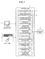
- FIG. 1 is a block diagram of a configuration of an image extracting apparatus according to an embodiment of the present invention.
- the image extracting apparatus shown in FIG. 1 includes a control unit 1 that has an operation function and a control function, a memory unit 2 that stores various kinds of information including image information of an image sequence, a display unit 3 that outputs and displays information including an image, and an input unit 4 such as a keyboard and a mouse.
- the image extracting apparatus is realized with a computer having a central processing unit (CPU), a read-only memory (ROM), a random access memory (RAM), and the like.
- CPU central processing unit
- ROM read-only memory
- RAM random access memory
- the control unit 1 has an image reading unit 11 that reads in images which are sequential in time series as an image sequence and are stored in the memory unit 2. Further, the control unit 1 has a scene-transition-image extraction unit 12 and a near-image display control unit 13.
- the scene-transition-image extraction unit 12 extracts a scene transition image from the images in the image sequence that is read in by the image reading unit 11, using a predetermined extraction condition.
- the near-image display control unit 13 controls the display unit 3 to display a near image captured at a time point in the neighborhood of time point at which the scene transition image extracted by the scene-transition-image extraction unit 12 is captured.
- control unit 1 has an operation history acquiring unit 14 and an extraction condition changing unit 15.
- the operation history acquiring unit 14 acquires image information of a near image, for which the user performs a predetermined viewing operation, among the near images displayed on the display unit 3, and history information of the operation indicating contents of the operation.
- the extraction condition changing unit 15 changes the extraction condition for extracting the scene transition image using the image information and the history information of the operation acquired by the operation history acquiring unit 14.
- the operation history acquiring unit 14 further acquires image information and history information of an operation of a scene transition image for which the user performs a predetermined viewing operation. Then, in changing the extraction condition, the extraction condition changing unit 15 uses the information of the scene transition image acquired by the operation history acquiring unit 14 in addition to the information of the near image.
- the scene-transition-image extraction unit 12 has a feature quantity calculation unit 121, a variation calculation unit 122, a variation information attachment unit 123, an integrated variation calculation unit 124, an extraction unit 125, and an extraction number setting unit 126.
- the feature quantity calculation unit 121 calculates a plurality of predetermined feature quantities for each image that is read in by the image reading unit 11.
- the variation calculation unit 122 calculates a variation of a feature quantity, which is calculated by the feature quantity calculation unit 121, between predetermined images.
- the variation information attachment unit 123 attaches information on feature quantity variation calculated by the variation calculation unit 122 to a corresponding image.
- the integrated variation calculation unit 124 calculates an integrated variation, which is a combination and integration of feature quantity variations of each image, using the information of feature quantity variations attached to each image. Further, the extraction unit 125 extracts a number of images from the image sequence using the integrated variation calculated by the integrated variation calculation unit 124 for each image. The number is set beforehand by the extraction number setting unit 126. Here, the number of images to be extracted is set beforehand by the extraction number setting unit 126. Alternatively, the user may input the extraction number to the extraction number setting unit 126 via the input unit 4.
- a CPU of the image extracting apparatus having each of the units described above reads out an image extraction program for performing an image extraction process according to the present embodiment from the memory unit 2, and performs an operation process related to the image extraction process.
- the image extraction program according to the present embodiment may be recorded in a computer-readable recording medium such as a flexible disk, a CD-ROM, a DVD-ROM, and a flash memory, so as to be widely distributed. Therefore, the image extracting apparatus may include an auxiliary memory device that can perform reading of one of the various kinds of recording mediums listed above.
- FIG. 2 is a flowchart of an image extraction process procedure according to the present embodiment.
- the image reading unit 11 reads in information such as a total number of images forming an image sequence and a size of an image from the memory unit 2 (Step S101).
- the feature quantity calculation unit 121 calculates the feature quantity of each image using the image information read in by the image reading unit 11 (Step S102).
- plural feature quantities are calculated for one image.
- the variation calculation unit 122 calculates the feature quantity variation between images separate from each other by a predetermined time interval (Step S103).
- the variation calculation unit 122 calculates a variation of each of the feature quantities.
- the variation information attachment unit 123 attaches information of the feature quantity variations calculated by the variation calculation unit 122 to a corresponding image (Step S104).
- the integrated variation calculation unit 124 calculates the integrated variation, which is a unique amount for each image, using the feature quantity variations attached to each image (Step S105). For example, the integrated variation calculation unit 124 calculates the integrated variation by weighting each feature quantity variation using a weighting factor set for each feature quantity, and integrating the weighted feature quantity variations.
- the weighting factor of each feature quantity is set as an extraction condition of the scene transition image.
- the extraction unit 125 extracts a number of images from the image sequence in descending order of integrated variation as the scene transition image (Step S106). The number is set by the extraction number setting unit 126. Further, the scene-transition-image extraction unit 12 outputs the scene transition images extracted by the extraction unit 125 and displays the scene transition images on the display unit 3 (Step S107).
- the control unit 1 determines whether the user selects any of the scene transition images displayed on the display unit 3 via the input unit 4 (Step S108). If image selection information indicating that an image is selected is acquired (Step S108: Yes), the near image display control unit 13 displays the selected scene transition image and near images of the selected scene transition image on the display unit 3 (Step S109). On the other hand, if the image selection information is not acquired (Step S108: No), the control unit 1 proceeds to step S110. Alternatively, near images may be displayed regardless of the selection of the scene transition image.
- the control unit 1 determines whether a display termination command on the scene transition image is acquired. If the display termination command on the scene transition image is not acquired (Step S110: No), the control unit 1 proceeds to step S107 and repeats the procedures described above. On the other hand, if the display termination command on the scene transition image is acquired (Step S110: Yes), the extraction condition changing unit 15 changes the extraction condition and stores the extraction condition in the memory unit 2 (Step S111).
- the extraction condition changing unit 15 changes the weighting factor, which is an extraction condition, of each feature quantity using information acquired by the operation history acquiring unit 14 before the termination command is acquired, more specifically, using the image information of the image, for which the user performs the predetermined viewing operation, among the scene transition image and the near images displayed on the display unit 3 and the history information of the operation.
- the control unit 1 proceeds to step S107 and repeats the procedures described above.
- Step S112 determines whether or not a re-extraction command on the scene transition image is input to the scene-transition-image extraction unit 12 (Step S112). If the re-extraction command on the scene transition image is input (Step S112: Yes), the control unit 1 proceeds to Step S105, where the integrated variation calculation unit 124 calculates the integrated variation of each image again using the changed weighting factor, and repeats the procedures at step S106 and subsequent steps. On the other hand, if the re-extraction command on the scene transition image is not input to the scene-transition-image extraction unit 12 (Step S112: No), the control unit 1 terminates the image extraction process.
- an image for which the user performs the predetermined viewing operation includes images for which the user performs a selection operation, and images for which an operation indicating that the image is not a key image is performed.
- An image for which an operation indicating that the image is not a key image is performed is, for example, an image for which a deletion operation is performed, and an image for which a jump operation such as a skip is performed while the images are sequentially displayed in order of time series, i.e., while the images are displayed as a movie.
- those are images for which the user does not perform the viewing operation on purpose.
- the image extracting apparatus extracts the scene transition image and the near image in the neighborhood of the scene transition image in the image extraction process shown in FIG. 2 , and displays the extracted images on the display unit 3.
- the image extracting apparatus changes the extraction condition using the image information of an image for which the user performs a viewing operation and a predetermined operation, among the scene transition image and the near image, and the history information of the operation, and then re-extracts the scene transition image using the changed extraction condition.
- FIG. 3 is a schematic diagram of a process to extract an image from an image sequence containing sequential images arranged in time series, using a predetermined extraction condition, and to change the extraction condition using image information of an image for which the predetermined viewing operation is performed, among the extracted images, and history information of the operation.
- An image sequence 10 which contains sequential images arranged in time series, has N images 10-1 to 10-N arranged at time interval ⁇ t to each adjacent image.
- a scene transition image sequence 20 containing n (n ⁇ N) pieces of scene transition images 20-1 to 20-n are extracted from the image sequence 10.
- the images 10-1 to 10-N are divided into n portions by the scene transition images 20-1 to 20-n.
- the scene transition images 20-1 to 20-n are displayed on the display unit 3.
- n' may be specified by the user or may be set as a predetermined value.
- the value may be set corresponding to the number of images between the scene transition image 20-(i-1) and the scene transition image 20-i or the number of images between the scene transition image 20-i and the scene transition image 20-(i+1). In the example shown in FIG.
- the near images 30-1 to 30-n' are n' images among images previous to or subsequent to the scene transition image.
- n' images previous to the scene transition image 20-i may be displayed as the near images, or n' images subsequent to the scene transition image 20-i may be displayed as the near images.
- the extraction condition is changed based on the image information of the image for which the user performs the predetermined viewing operation such as the selection operation, for example, based on the image information of the scene transition image 20-i and the near image 30-i' shown in FIG. 3 , and the history information of the operation.
- FIG. 4 is a diagram of a display example of the scene transition images and the near images.
- the scene transition images 20-1 to 20-n are displayed as thumbnails on a display screen 3a of the display unit 3.
- the near image sequence containing the near images 30-1 to 30-n' is displayed as a movie on a movie display area 50.
- the movie display area 50 has a pause button 51, a play button 52, a reverse play button 53, a frame advance forward button 54, and a frame advance backward button 55.
- the pause button 51 is a button which allows an input of a command to the control unit 1 to pause the displayed movie and keep the displayed movie still until other operation is performed.
- the play button 52 is a button which allows an input of a command to the control unit 1 to display images sequentially in order of time series
- the reverse play button 53 is a button which allows an input of a command to the control unit 1 to play the images sequentially in reverse order of time series.
- the frame advance forward button 54 and the frame advance backward button 55 are buttons which allow inputs of a command to the control unit 1 to slow down a play-speed in a corresponding direction, and to lengthen display time of each image.
- an image for which the user performs the viewing operation and the predetermined operation is an image displayed on the display unit 3 when the button described above is selected by the user.
- FIG. 5 is a diagram of an example of images in the image sequence 10.
- the three star-shaped objects 401, 402, and 403 are the same object.
- FIG. 5 illustrates a case where the star-shaped object is in constant motion horizontally rightward within the same visual field.
- a crescent-shaped object 412 that is smaller than the star-shaped object 402 also appears in the image 42.
- the feature quantity of the images shown in FIG. 5 is, for example, a color and a number of pixels of the objects 401, 402, and 403. Further, the feature quantity may be calculated based on an edge extraction image shown in FIG. 6 which is acquired through an edge extraction process (or a contour extraction process) on the objects 401, 402, 403, and 412 in the images 41, 42, and 43 shown in FIG. 5 .
- an edge 401e of the object 401 is shown in an edge extraction image 41e.
- An edge 402e of the object 402 and an edge 412e of the object 412 are shown in an edge extraction image 42e.
- An edge 403e of the object 403 is shown in an edge extraction image 43e.
- an area of a portion surrounded by the edge (hereinafter referred to as "area of edge”) is set as one feature quantity of the image.
- the area of the edge 401e which is a feature quantity of the image 41 is the same as the area of the edge 402e which is a feature quantity of the image 42, whereas the area of the edge 403e which is a feature quantity of the image 43 is smaller than the area of the edge 401e or the area of the edge 402e.
- the image extracting apparatus extracts the image 43 from the images 41, 42, and 43 as the scene transition image and displays the image 43 on the display unit 3.
- the image extracting apparatus displays the near image of the scene transition image selected by the user. Therefore, when the user selects the image 43, the image extracting apparatus displays a predetermined number of near images including the image 42 on the display unit 3.
- an image in which the crescent-shaped object 412 appears is an image the user desires as the scene transition image
- the user may perform the predetermined viewing operation such as the selection operation on the image 42.
- the image extracting apparatus changes the extraction condition, using the image information of the image 42.
- the extraction condition is changed so that an image in which the crescent-shaped object 412 appears is more likely to be extracted as the scene transition image in subsequent extraction of the scene transition image.
- the image extracting device changes the extraction condition so as to increase the weighting factor of the variation of the feature quantity such as a color and a shape of an object.
- a quantity other than the feature quantities described above may be used as the feature quantity variation of an image.
- normalized cross-correlation may be used as the feature quantity variation, and also a degree of similarity such as SSD (sum of squared differences between corresponding pixels), and SAD (sum of absolute values of differences between corresponding pixels) may be used as the feature quantity variation.
- SSD or SAD of results acquired by multiplication or division of average pixel value of all images in the image sequence may be used as the feature quantity variation.
- SSD or SAD of results acquired by multiplication or division of average pixel value of each image acquired by dividing an image may be used as the feature quantity variation.
- it is possible to calculate a point selected regularly within a space e.g.
- the feature quantity variations mentioned above are qualitatively different from the variation calculated based on the area surrounded by the edge as the feature quantity.
- M is an integer larger than or equal to 2
- N is a number of images in the image sequence 10.
- image information of the images 10-1 to 10-N in the image sequence 10 is set as I 1 to IN sequentially in order of time the images are captured.
- the feature quantity variations attached to the images in the image sequence 10 can be represented by a variation matrix ⁇ F of the following formula (1), where ⁇ F qp represents a p-th feature quantity that is attached to a q-th image by the variation information attachment unit 123.
- ⁇ F ⁇ F 11 ⁇ F 12 ⁇ ⁇ F 1 ⁇ p ⁇ ⁇ F 1 ⁇ M ⁇ F 21 ⁇ ⁇ ⁇ ⁇ ⁇ ⁇ F q ⁇ 1 ⁇ ⁇ ⁇ F pq ⁇ ⁇ ⁇ ⁇ F N ⁇ 1 ⁇ F NM
- a vector consists simply of variations of respective feature quantities as its components, when a threshold process is performed on the size of the vector, an influence of a feature quantity with relatively high value becomes dominant and an influence of a feature quantity with relatively low value is not reflected.
- a normalization process is performed on the feature quantity variations calculated by the variation calculation unit 122.
- a vector of the feature quantity variations whose components are values obtained through the normalization process is employed as a variation vector of each image.
- variation vector f q of an image 10-q is expressed by the following formula (2).
- W 1 to W M are weighting factors different for each feature quantity.
- the integrated variation Simq represents a degree of similarity between predetermined images.
- Simq is low, a degree of similarity between predetermined images is high. Therefore, the extraction unit 125 in the scene-transition-image extraction unit 12 extracts a predetermined number of images in descending order of the integrated variation Sim q as the scene transition image.
- the near-image display control unit 13 displays on the display unit 3 a predetermined number of images which are near the scene transition image selected by the user.
- the extraction condition changing unit 15 calculates a weighting factor matrix w' using image information of an image for which the user performs the viewing operation and the predetermined operation, history information of the operation, and formula (6).
- w and w' are matrixes of weighting factors, and are expressed by the following formulas (7) and (8).
- F i and F j are matrixes representing the variations of feature quantities for each image, and are expressed by the following formulas (9) and (10).
- ⁇ , ⁇ , and ⁇ are constant numbers larger than or equal to 0.
- the constant numbers ⁇ , ⁇ , and ⁇ are set based on a relation between the integrated variation Simq and the changed weighting factor matrix w'.
- D R represents a group of images desired by the user
- D N represents a group of images not desired by the user.
- the extraction condition changing unit 15 determines whether an image is desired by the user or not using the history information of the operation. Using the formula (6), the extraction condition changing unit 15 changes the weighting factor so that the feature quantity with a large variation is weighted heavier in an image desired by the user while the feature quantity with a large variation is weighted lighter in an image not desired by the user.
- the extraction condition changing unit 15 assigns information of changed feature quantity variation matrixes F i and F j , and the unchanged weighting factor matrix w in the formula (6). Then, the extraction condition changing unit 15 increases/decreases the constant numbers ⁇ , ⁇ , and ⁇ to find the weighting factor matrix w', according to which the integrated variation Sim q of a predetermined image is lowest. The extraction condition changing unit 15 calculates the integrated variation Simq of images other than the predetermined image, using the found weighting factor matrix w'.
- the image extracting apparatus can change the extraction condition of the scene transition image using image information of the scene transition image 20-i, which is extracted according to the predetermined extraction condition of the scene transition image, as well as image information of the near image 30-i', which is not extracted according to the predetermined extraction condition.
- the image extracting apparatus can change the extraction condition extensively reflecting an intention of the user, for example, by complementing the predetermined extraction condition with a condition which is not included therein. Therefore, the image extracting apparatus according to the embodiment is effective in successfully extracting the scene transition image desired by the user.
- the near image is a number of images near the scene transition image, and the number is set according to the number of images between the scene transition images.
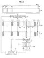
- a first modification at least half of the images between the scene transition images are treated as the near image. For example, as shown in FIG.
- the near-image display control unit 13 displays on the display unit 3 a near image sequence 31, which contains half a number of images near the scene transition image 20-i and captured during a time period between a time when the scene transition image 20-i selected by the user is captured and a time when the scene transition image 20-(i-1) is captured, and also contains half a number of images near the scene transition image 20-i and captured during a time period between the time when the scene transition image 20-i selected by the user is captured and a time when the scene transition image 20-(i+1) is captured.
- the near-image display control unit 13 displays as the near images on the display unit 3 at least half a number of images captured previous to and subsequent to the scene transition image 20-i during the time period between the time when the scene transition image 20-i is captured and a time when another scene transition image is captured.
- each image in the image sequence 10 is either the scene transition image or the near image
- the image extracting apparatus according to the first modification can change the extraction condition using image information of any image in the image sequence 10. Therefore, the image extracting apparatus according to the first modification is effective in more securely extracting the scene transition image desired by the user.
- a second modification at least all images captured during a time period between a time when the predetermined scene transition image is captured and a time when another scene transition image is captured are displayed as the near images.
- the image extracting apparatus displays all images between the scene transition image 20-i selected by the user and the scene transition image 20-(i+1), as a near image sequence 32 of the scene transition image 20-i.
- the image extracting apparatus displays at least all images in a previous scene or a subsequent scene of the scene transition image 20-i selected by the user. Therefore, the user can view images scene by scene and grasp a general content of the scene between the scene transition images before changing the extraction condition.
- the image extracting apparatus may display images, from an image that is one or more images previous to the scene transition image 20-i to the scene transition image 20-(i+1), as near images.
- the image extracting apparatus may display all images in a previous scene and a subsequent scene of the scene transition image, that is, all images in two scenes before and after the scene transition image.
- each image in the image sequence 10 is either the scene transition image or the near image, and the image extracting apparatus can change the extraction condition using image information of any image in the image sequence 10. Therefore, the image extracting apparatus is effective in even more securely extracting the scene transition image desired by the user.
- the image extracting apparatus displays the scene transition images 20-1 to 20-n as thumbnails on the display screen 3a.
- An image extracting apparatus according to a third modification displays the scene transition images 20-1 to 20-n as a movie on the display screen 3a.
- the image extracting apparatus according to the third modification displays the scene transition images 20-1 to 20-n in order of time series as a movie.
- the image extracting apparatus according to the third modification displays as a movie on the display screen 3a the near images of the scene transition image 20-i that is displayed on the display screen 3a when the user selects the selection button 56.
- the near images displayed are any of the near images described with reference to FIGS. 3 , 7 , and 8 .
- the image extracting apparatus displays the scene transition image one by one on the display screen 3a, decreasing a risk of user's missing a scene transition image desired by the user by not noticing the image even though the image is displayed.
- the image extracting apparatus displays the near images 30-1 to 30-n' as a movie.
- An image extracting apparatus according to a fourth modification displays the near images 30-1 to 30-n' as thumbnails. As shown in FIG. 10 , when the scene transition image 20-i is selected, the image extracting apparatus according to the fourth modification displays the scene transition image 20-i and the near images 30-1 to 30-n' as thumbnails.
- the image extracting apparatus displays the scene transition image 20-i and the near images 30-1 to 30-n' together, the user can view each image in comparison with other images. Therefore, the image extracting apparatus according to the fourth modification allows the user to successfully identify a difference between the near images and to easily find a desired image.
- the image for which the predetermined viewing operation is performed is an image for which the user performs the selection operation or the deletion operation.
- an image for which a pointing operation (clicking, for example) with a pointing device (pointer, for example) is performed as shown in FIG. 10
- an image on which a movement trace of the pointing device passes in other words, an image on which the pointer passes when viewed on the display screen 3a as shown in FIG. 11 are included in the image for which the predetermined viewing operation is performed.
- An image extracting apparatus can use, on changing the extraction condition, information of an image which attracts attention of the user though the user does not positively perform the selection operation thereon, for example, an image on which the user clicks and an image over which the user passes the pointer.
- the extraction condition can be changed so as to reflect an intention of the user more extensively in comparison with the embodiment described above. Therefore, the scene transition image desired by the user can be more securely extracted.
- the image extracting apparatus may treat an image for which a command is issued for switching-over between the movie display and the thumbnail display as the image for which the predetermined viewing operation is performed.
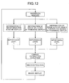
- the extraction condition changing unit 15 determines whether an image for which the user performs an operation is an image desired by the user or not using history information of the operation, before changing the extraction condition using image information of each image.
- the image information is further weighted according to the content of operation the user performs, and employed for changing the extraction condition.
- an image extracting apparatus sets an importance level of image information according to the operation the user performs and weights the image information of the image for which the predetermined operation is performed.
- the importance level is set to "1" meaning that it is most important information
- the importance level is set to "k” meaning that the information is not important though consideration should be paid.
- the weight of the image information of the image on which the pointer passes is set one third the weight of the image information of the image for which the user performs the selection operation.
- the extraction condition changing unit 15 assigns each value of a feature quantity variation matrix F i , of an image for which the user performs the selection operation as it is, and one third of each value of a feature quantity variation matrix F i , of the image on which the pointer passes, to the formula (6). Then, the extraction condition changing unit 15 calculates the weighting factor matrix w' of the feature quantity, that is, the extraction condition.
- the image extracting apparatus estimates an importance level of each image for the user, using the history information of the operation, and changes the extraction condition using the image information weighted according to the importance level.
- an intention of the user can be reflected more accurately in changed extraction condition. Therefore, the scene transition image desired by the user can be more securely extracted.
- FIG. 13 is a schematic diagram of one example of an intra-subject information acquiring system provided with the image extracting apparatus of the example.
- 13 has a capsule endoscope 5 that is introduced inside a body cavity of a subject H and captures an intra-body-cavity image, a receiving device 6 that receives a radio signal transmitted from the capsule endoscope 5 and stores an image included in the received radio signal, and the memory unit 2 such as a portable, removable memory card attachable to and detachable from the receiving device 6 and the image extracting apparatus.
- the capsule endoscope 5 has an imaging function to capture an intra-body-cavity image of the subject H, and a radio communication function to transmit a radio signal including a captured image to an outside. To be more specific, the capsule endoscope 5 travels inside the body cavity of the subject H while capturing intra-body-cavity images at predetermined intervals, for example, at approximately 0.5-second intervals (i.e. about 2 Hz), and transmits the captured intra-body-cavity images on a predetermined radio wave to the receiving device 6.
- predetermined intervals for example, at approximately 0.5-second intervals (i.e. about 2 Hz)
- the receiving device 6 is connected to receiving antennas 6a to 6h which receive a radio signal transmitted from the capsule endoscope 5.
- the receiving antennas 6a to 6h are realized, for example, with a loop antenna, and arranged in a scattering manner on a surface of the body of the subject H corresponding to a travel path of the capsule endoscope 5.
- a total number of arranged receiving antennas is not limited to eight as illustrated in the figure.
- the receiving device 6 receives via one of the receiving antennas 6a to 6h the radio signal transmitted from the capsule endoscope 5, and acquires image information of the intra-body-cavity image of the subject H from the received radio signal.
- the image information acquired by the receiving device 6 is stored in the memory unit 2 attached to the receiving device 6.
- the memory unit 2 storing the image information of the intra-body-cavity image of the subject H is then attached to the image extracting apparatus and used for the process in the control unit.
- the capsule endoscope 5 travels inside the body cavity of the subject H for approximately eight hours while capturing an enormous amount of images, e.g., approximately 60000 image, and creates an intra-body-cavity image sequence.
- the intra-body-cavity image sequence may contain many similar images, for example, in a scene captured while the capsule endoscope 5 is in the same internal organ, and thus it is not practical for a person to observe all images.
- the extraction condition of the scene transition image is changed so that an image in which a subject of interest of each doctor appears is extracted as the scene transition image from the intra-body-cavity image sequence of large amount captured by the capsule endoscope 5. Then, the scene transition image is re-extracted based on the extraction condition.
- the extraction condition is changed according to the image information of an image selected from the scene transition images and near images by a doctor, and the history information of the operation by the doctor, and the scene transition image is re-extracted based on the changed extraction condition. Therefore, the doctor can easily search for a desired image and make diagnosis in a short time.
- the image extracting apparatus included in the intra-subject information acquiring system according to the example further includes an organ specification unit 16 that specifies an organ appears in each image as shown in FIG. 14 .
- the extraction condition of the scene transition image is changed for each organ which appears in the image.
- information acquired by the operation history acquiring unit 14 is classified according to organs specified by the organ specification unit 16.
- the extraction condition changing unit 17 changes the extraction condition for each organ using the classified information.
- the scene-transition-image extraction unit 12 re-extracts the scene transition image changing the extraction condition for each organ appears in each image.
- the image extracting apparatus according to the modification of the example which changes the extraction condition for each organ, allows for an even more secure extraction of the scene transition image desired by the doctor in comparison with the image extracting apparatus of the example.
- an image extracting apparatus, an image extraction program, and an image extracting method according to the present invention are useful for extracting a sequence of images serially captured, a point where a scene transition occurs in an image sequence of dynamic image frames, and a valid image.
Landscapes
- Health & Medical Sciences (AREA)
- Life Sciences & Earth Sciences (AREA)
- Engineering & Computer Science (AREA)
- Surgery (AREA)
- Physics & Mathematics (AREA)
- Public Health (AREA)
- Pathology (AREA)
- Radiology & Medical Imaging (AREA)
- Optics & Photonics (AREA)
- Nuclear Medicine, Radiotherapy & Molecular Imaging (AREA)
- Biomedical Technology (AREA)
- Heart & Thoracic Surgery (AREA)
- Medical Informatics (AREA)
- Molecular Biology (AREA)
- Animal Behavior & Ethology (AREA)
- General Health & Medical Sciences (AREA)
- Biophysics (AREA)
- Veterinary Medicine (AREA)
- Theoretical Computer Science (AREA)
- Multimedia (AREA)
- General Physics & Mathematics (AREA)
- Signal Processing (AREA)
- Computing Systems (AREA)
- General Engineering & Computer Science (AREA)
- Databases & Information Systems (AREA)
- Data Mining & Analysis (AREA)
- Television Signal Processing For Recording (AREA)
- Closed-Circuit Television Systems (AREA)
- Processing Or Creating Images (AREA)
- Two-Way Televisions, Distribution Of Moving Picture Or The Like (AREA)
- Information Retrieval, Db Structures And Fs Structures Therefor (AREA)
- Image Analysis (AREA)
Applications Claiming Priority (2)
| Application Number | Priority Date | Filing Date | Title |
|---|---|---|---|
| JP2007190072A JP5203648B2 (ja) | 2007-07-20 | 2007-07-20 | 画像抽出装置および画像抽出プログラム |
| PCT/JP2008/060299 WO2009013940A1 (ja) | 2007-07-20 | 2008-06-04 | 画像抽出装置、画像抽出プログラムおよび画像抽出方法 |
Publications (2)
| Publication Number | Publication Date |
|---|---|
| EP2172145A1 true EP2172145A1 (de) | 2010-04-07 |
| EP2172145A4 EP2172145A4 (de) | 2018-01-10 |
Family
ID=40264893
Family Applications (1)
| Application Number | Title | Priority Date | Filing Date |
|---|---|---|---|
| EP08765112.1A Withdrawn EP2172145A4 (de) | 2007-07-20 | 2008-06-04 | Bildextraktionsvorrichtung, bildextraktionsprogramm und bildextraktionsverfahren |
Country Status (5)
| Country | Link |
|---|---|
| US (1) | US8254720B2 (de) |
| EP (1) | EP2172145A4 (de) |
| JP (1) | JP5203648B2 (de) |
| CN (1) | CN101754713B (de) |
| WO (1) | WO2009013940A1 (de) |
Families Citing this family (27)
| Publication number | Priority date | Publication date | Assignee | Title |
|---|---|---|---|---|
| US8259177B2 (en) * | 2008-06-30 | 2012-09-04 | Cisco Technology, Inc. | Video fingerprint systems and methods |
| US8665326B2 (en) * | 2009-01-30 | 2014-03-04 | Olympus Corporation | Scene-change detecting device, computer readable storage medium storing scene-change detection program, and scene-change detecting method |
| CN102361585B (zh) * | 2009-03-23 | 2014-06-25 | 奥林巴斯医疗株式会社 | 图像处理系统、外部装置以及图像处理系统的图像处理方法 |
| US8411321B2 (en) * | 2009-09-09 | 2013-04-02 | Seiko Epson Corporation | Printing apparatus, layout adjustment method, program and recording medium |
| JP5495101B2 (ja) * | 2009-09-15 | 2014-05-21 | 株式会社リコー | 動画サムネイル作成装置、方法及びプログラム |
| JP2011254240A (ja) * | 2010-06-01 | 2011-12-15 | Sony Corp | 画像処理装置、画像処理方法およびプログラム |
| JP5725745B2 (ja) * | 2010-07-05 | 2015-05-27 | 株式会社東芝 | X線診断装置及び医用画像診断装置 |
| JP5784404B2 (ja) * | 2011-07-29 | 2015-09-24 | オリンパス株式会社 | 画像処理装置、画像処理方法、及び画像処理プログラム |
| JP5242866B1 (ja) * | 2011-08-12 | 2013-07-24 | オリンパスメディカルシステムズ株式会社 | 画像管理装置、方法、及び読影用プログラム |
| JP5899856B2 (ja) | 2011-11-18 | 2016-04-06 | ソニー株式会社 | 情報処理装置、情報処理方法及びプログラム |
| WO2014103879A1 (ja) * | 2012-12-26 | 2014-07-03 | オリンパスメディカルシステムズ株式会社 | 画像記録装置及び画像記録方法 |
| JP5820986B2 (ja) * | 2013-03-26 | 2015-11-24 | パナソニックIpマネジメント株式会社 | 映像受信装置及び受信映像の画像認識方法 |
| JP6281126B2 (ja) | 2013-07-26 | 2018-02-21 | パナソニックIpマネジメント株式会社 | 映像受信装置、付加情報表示方法および付加情報表示システム |
| EP3029944B1 (de) | 2013-07-30 | 2019-03-06 | Panasonic Intellectual Property Management Co., Ltd. | Videoempfangsvorrichtung, verfahren zur anzeige hinzugefügter informationen und system zur anzeige hinzugefügter informationen |
| WO2015033500A1 (ja) | 2013-09-04 | 2015-03-12 | パナソニックIpマネジメント株式会社 | 映像受信装置、映像認識方法および付加情報表示システム |
| JP6240899B2 (ja) | 2013-09-04 | 2017-12-06 | パナソニックIpマネジメント株式会社 | 映像受信装置、映像認識方法および付加情報表示システム |
| CN104954717B (zh) * | 2014-03-24 | 2018-07-24 | 宇龙计算机通信科技(深圳)有限公司 | 一种终端及视频片头生成方法 |
| CN105144734B (zh) | 2014-03-26 | 2018-11-06 | 松下知识产权经营株式会社 | 影像接收装置、影像识别方法以及附加信息显示系统 |
| EP3125567B1 (de) | 2014-03-26 | 2019-09-04 | Panasonic Intellectual Property Management Co., Ltd. | Videoempfangsvorrichtung, videoerkennungsverfahren und zusatzinformationsanzeigesystem |
| JP6471359B2 (ja) | 2014-07-17 | 2019-02-20 | パナソニックIpマネジメント株式会社 | 認識データ生成装置、画像認識装置および認識データ生成方法 |
| WO2016027457A1 (ja) | 2014-08-21 | 2016-02-25 | パナソニックIpマネジメント株式会社 | コンテンツ認識装置およびコンテンツ認識方法 |
| US10143364B2 (en) | 2015-07-23 | 2018-12-04 | Ankon Technologies Co., Ltd | Controlled image capturing method including position tracking and system used therein |
| JP2020127440A (ja) * | 2017-04-28 | 2020-08-27 | オリンパス株式会社 | 内視鏡画像観察支援システム |
| EP4026479A4 (de) * | 2019-09-03 | 2022-11-02 | FUJIFILM Corporation | Vorrichtung zur verarbeitung medizinischer bilder, prozessor, endoskopsystem, verfahren zur verarbeitung medizinischer bilder und programm |
| WO2021241695A1 (ja) * | 2020-05-27 | 2021-12-02 | 富士フイルム株式会社 | 内視鏡画像処理装置 |
| CN113889059B (zh) * | 2021-09-24 | 2025-06-17 | 北京航空航天大学 | 一种基于音视频节奏关系的视频背景音乐自动生成方法 |
| JP7725417B2 (ja) * | 2022-04-21 | 2025-08-19 | キヤノン株式会社 | 監視装置、監視方法、コンピュータプログラム、及び記憶媒体 |
Family Cites Families (21)
| Publication number | Priority date | Publication date | Assignee | Title |
|---|---|---|---|---|
| GB2256567B (en) * | 1991-06-05 | 1995-01-11 | Sony Broadcast & Communication | Modelling system for imaging three-dimensional models |
| JPH0993527A (ja) * | 1995-09-21 | 1997-04-04 | Nippon Telegr & Teleph Corp <Ntt> | 映像インデックス作成装置 |
| JPH10108122A (ja) * | 1996-09-26 | 1998-04-24 | Nikon Corp | 画像再生装置 |
| JP3585400B2 (ja) | 1999-08-05 | 2004-11-04 | シャープ株式会社 | 動画像編集拾い見装置 |
| US20020051077A1 (en) * | 2000-07-19 | 2002-05-02 | Shih-Ping Liou | Videoabstracts: a system for generating video summaries |
| WO2004075547A1 (ja) * | 2003-02-19 | 2004-09-02 | Matsushita Electric Industrial Co., Ltd. | 記録媒体、再生装置、記録方法、プログラム、再生方法 |
| EP1790277B1 (de) * | 2004-08-23 | 2018-11-21 | Olympus Corporation | Bildanzeigevorrichtung und bildanzeigeprogramm |
| JP4598458B2 (ja) * | 2004-08-30 | 2010-12-15 | オリンパス株式会社 | 画像表示装置、画像表示方法および画像表示プログラム |
| DE102004056958B3 (de) * | 2004-11-22 | 2006-08-10 | IQ wireless GmbH, Entwicklungsgesellschaft für Systeme und Technologien der Telekommunikation | Verfahren für die Überwachung von Territorien zur Erkennung von Wald- und Flächenbränden |
| JP4699014B2 (ja) * | 2004-11-29 | 2011-06-08 | オリンパス株式会社 | 画像表示装置、画像表示方法および画像表示プログラム |
| JP2006217045A (ja) * | 2005-02-01 | 2006-08-17 | Olympus Corp | インデックス画像生成装置及びインデックス画像を生成するプログラム |
| JP2006217046A (ja) * | 2005-02-01 | 2006-08-17 | Olympus Corp | 映像インデックス画像生成装置及び映像のインデックス画像を生成するプログラム |
| US8335357B2 (en) * | 2005-03-04 | 2012-12-18 | Kabushiki Kaisha Toshiba | Image processing apparatus |
| EP1862106A1 (de) * | 2005-03-22 | 2007-12-05 | Osaka University | Kapselendoskop-bildanzeigeregler |
| WO2006102905A1 (en) * | 2005-03-31 | 2006-10-05 | Gregersen Enterprises 2005 Aps | Apparatus and method for a global model of hollow internal organs including the determination of cross-sectional areas and volume in internal hollow organs and wall properties |
| JP4547293B2 (ja) * | 2005-04-04 | 2010-09-22 | オリンパス株式会社 | 画像表示装置 |
| JP2007075163A (ja) * | 2005-09-09 | 2007-03-29 | Olympus Medical Systems Corp | 画像表示装置 |
| JP4707713B2 (ja) * | 2005-08-11 | 2011-06-22 | 三菱電機株式会社 | 映像記録装置及びシーンチェンジ抽出方法 |
| JP2007166090A (ja) * | 2005-12-12 | 2007-06-28 | Matsushita Electric Ind Co Ltd | コンテンツ再生/編集装置、コンテンツ再生/編集方法、コンテンツ再生/編集プログラム及びコンテンツ再生/編集プログラムを格納した記録媒体 |
| US20080181507A1 (en) * | 2007-01-29 | 2008-07-31 | Intellivision Technologies Corp. | Image manipulation for videos and still images |
| JP5147308B2 (ja) * | 2007-06-20 | 2013-02-20 | オリンパス株式会社 | 画像抽出装置および画像抽出プログラム |
-
2007
- 2007-07-20 JP JP2007190072A patent/JP5203648B2/ja not_active Expired - Fee Related
-
2008
- 2008-06-04 CN CN2008800253898A patent/CN101754713B/zh not_active Expired - Fee Related
- 2008-06-04 WO PCT/JP2008/060299 patent/WO2009013940A1/ja not_active Ceased
- 2008-06-04 EP EP08765112.1A patent/EP2172145A4/de not_active Withdrawn
- 2008-07-14 US US12/172,616 patent/US8254720B2/en not_active Expired - Fee Related
Non-Patent Citations (1)
| Title |
|---|
| See references of WO2009013940A1 * |
Also Published As
| Publication number | Publication date |
|---|---|
| EP2172145A4 (de) | 2018-01-10 |
| JP2009027558A (ja) | 2009-02-05 |
| WO2009013940A1 (ja) | 2009-01-29 |
| JP5203648B2 (ja) | 2013-06-05 |
| CN101754713B (zh) | 2011-10-05 |
| US8254720B2 (en) | 2012-08-28 |
| CN101754713A (zh) | 2010-06-23 |
| US20090022400A1 (en) | 2009-01-22 |
Similar Documents
| Publication | Publication Date | Title |
|---|---|---|
| EP2172145A1 (de) | Bildextraktionsvorrichtung, bildextraktionsprogramm und bildextraktionsverfahren | |
| US8135192B2 (en) | Image processing apparatus and image processing method | |
| EP2157789A1 (de) | Bildextraktionsvorrichtung, bildextraktionsprogramm und bildextraktionsverfahren | |
| Chen et al. | Breast cancer diagnosis using self-organizing map for sonography | |
| EP3998579B1 (de) | Medizinisches bildverarbeitungsverfahren, gerät und vorrichtung, medium und endoskop | |
| US9008390B2 (en) | Similar case searching apparatus, relevance database generating apparatus, similar case searching method, and relevance database generating method | |
| EP1862106A1 (de) | Kapselendoskop-bildanzeigeregler | |
| EP2357612B1 (de) | Verfahren zur Quantifizierung und Bildgebung von Merkmalen eines Tumors | |
| US11556731B2 (en) | Endoscopic image observation system, endosopic image observation device, and endoscopic image observation method | |
| US20100183204A1 (en) | Image processing device, image processing method, and computer readable storage medium storing image processing program | |
| EP1847940A2 (de) | System zur Bewertung eines Patientenzustands und Verfahren zur Verareitung dazugehöriger Daten | |
| CN101273916B (zh) | 评估患者状况的系统和方法 | |
| US20070031020A1 (en) | Method and apparatus for intracerebral hemorrhage lesion segmentation | |
| JP2010167042A (ja) | 医用診断支援装置及びその制御方法、並びに、プログラム | |
| Zeng et al. | Optimization of digital breast tomosynthesis (DBT) acquisition parameters for human observers: effect of reconstruction algorithms | |
| CN113140291B (zh) | 图像分割方法、装置、模型训练方法及电子设备 | |
| JP6425868B1 (ja) | 内視鏡画像観察支援システム、内視鏡画像観察支援装置、内視鏡画像観察支援方法 | |
| JP4797194B2 (ja) | 超音波断層画像による生体組織評価システム | |
| Sato et al. | Large batch and patch size training for medical image segmentation | |
| Suman et al. | Optimum colour space selection for ulcerated regions using statistical analysis and classification of ulcerated frames from wce video footage | |
| JP2007105458A (ja) | 画像データベースにおける画像の認識のためのシステム及び方法 | |
| Kahofer et al. | Tissue counter analysis of dermatoscopic images of melanocytic skin tumours: preliminary findings | |
| US20240005493A1 (en) | Method for identifying a type of organ in a volumetric medical image | |
| Semizer et al. | Texture as a diagnostic signal in mammograms | |
| Platiša et al. | Volumetric detection tasks with varying complexity: human observer performance |
Legal Events
| Date | Code | Title | Description |
|---|---|---|---|
| PUAI | Public reference made under article 153(3) epc to a published international application that has entered the european phase |
Free format text: ORIGINAL CODE: 0009012 |
|
| 17P | Request for examination filed |
Effective date: 20100203 |
|
| AK | Designated contracting states |
Kind code of ref document: A1 Designated state(s): AT BE BG CH CY CZ DE DK EE ES FI FR GB GR HR HU IE IS IT LI LT LU LV MC MT NL NO PL PT RO SE SI SK TR |
|
| AX | Request for extension of the european patent |
Extension state: AL BA MK RS |
|
| DAX | Request for extension of the european patent (deleted) | ||
| RAP1 | Party data changed (applicant data changed or rights of an application transferred) |
Owner name: OLYMPUS CORPORATION |
|
| RAP1 | Party data changed (applicant data changed or rights of an application transferred) |
Owner name: OLYMPUS CORPORATION |
|
| RAP1 | Party data changed (applicant data changed or rights of an application transferred) |
Owner name: OLYMPUS CORPORATION |
|
| RIN1 | Information on inventor provided before grant (corrected) |
Inventor name: MATSUZAKI, HIROSHI |
|
| RA4 | Supplementary search report drawn up and despatched (corrected) |
Effective date: 20171213 |
|
| RIC1 | Information provided on ipc code assigned before grant |
Ipc: G11B 27/34 20060101ALI20171207BHEP Ipc: G11B 27/32 20060101ALI20171207BHEP Ipc: H04N 7/18 20060101ALI20171207BHEP Ipc: G06F 17/30 20060101ALI20171207BHEP Ipc: H04N 5/76 20060101ALI20171207BHEP Ipc: G06K 9/00 20060101ALI20171207BHEP Ipc: A61B 1/04 20060101ALI20171207BHEP Ipc: G11B 27/28 20060101ALI20171207BHEP Ipc: H04N 5/91 20060101ALI20171207BHEP Ipc: A61B 1/00 20060101AFI20171207BHEP |
|
| STAA | Information on the status of an ep patent application or granted ep patent |
Free format text: STATUS: THE APPLICATION HAS BEEN WITHDRAWN |
|
| 18W | Application withdrawn |
Effective date: 20180208 |