EP2172826B1 - Dispositif et procédé destinés à déterminer un parcours de voie de circulation - Google Patents
Dispositif et procédé destinés à déterminer un parcours de voie de circulation Download PDFInfo
- Publication number
- EP2172826B1 EP2172826B1 EP09167913A EP09167913A EP2172826B1 EP 2172826 B1 EP2172826 B1 EP 2172826B1 EP 09167913 A EP09167913 A EP 09167913A EP 09167913 A EP09167913 A EP 09167913A EP 2172826 B1 EP2172826 B1 EP 2172826B1
- Authority
- EP
- European Patent Office
- Prior art keywords
- lane
- segment
- curvature
- class
- current
- Prior art date
- Legal status (The legal status is an assumption and is not a legal conclusion. Google has not performed a legal analysis and makes no representation as to the accuracy of the status listed.)
- Not-in-force
Links
Images



Classifications
-
- G—PHYSICS
- G06—COMPUTING OR CALCULATING; COUNTING
- G06V—IMAGE OR VIDEO RECOGNITION OR UNDERSTANDING
- G06V20/00—Scenes; Scene-specific elements
- G06V20/50—Context or environment of the image
- G06V20/56—Context or environment of the image exterior to a vehicle by using sensors mounted on the vehicle
- G06V20/588—Recognition of the road, e.g. of lane markings; Recognition of the vehicle driving pattern in relation to the road
Definitions
- the present invention relates to a method for determining a course of a lane traveled by a vehicle. Furthermore, the invention relates to a computer program product and a device for determining a course of a lane traveled by a vehicle.
- driver assistance systems for lateral guidance for motor vehicles, which warn the driver against unintentional leaving the own lane (Lane Departure Warning - LDW) or the driver by steering intervention while holding the vehicle in their own lane support (Lane Keeping Support - LKS ).
- LDW Long Departure Warning
- LKS Lane Keeping Support
- the requirements of these systems on the accuracy, quality and availability of the lane information are much higher than those of driver assistance systems for longitudinal guidance such as e.g. satellite-based navigation systems or ACC (Adaptive Cruise Control).
- Driver assistance systems for transverse guidance therefore usually work with environmental sensors, such as e.g. Video sensors and a downstream evaluation software, which detects lane markings of the traffic lane traveled by the vehicle in the front of their own vehicle traffic lane and describes their course on the basis of a model. Depending on the position of the vehicle relative to the lane markings and its predicted further direction of travel is then judged whether the vehicle threatens to leave the lane to deliver in the given case warning signals or to initiate steering interventions. Due to the measuring principle used, however, there are inaccuracies in the detection of the lane markings. In addition, the lane markings do not necessarily reflect the actual lane course exactly. This leads u. a. to oscillations of parameters of the model curves, with which the evaluation software describes the course of the lane markings, which ultimately has a negative effect on the reliability and comfort of driver assistance functions such as LDW or LKS.
- environmental sensors such as e.g. Video sensors and a downstream evaluation software, which detects lane markings of the traffic lane
- the US Pat. No. 6,560,535 B2 discloses a method in which for determining the position of a vehicle with high-precision data from a satellite-based positioning system can be combined with additional data such as the vehicle's odometer reading, wheel revolutions of an anti-lock braking system, direction of travel and / or inclination measurements.
- the position thus determined is compared with a digital road map to detect when the vehicle leaves a lane.
- currently common digital maps for vehicle navigation systems have a resolution that is sufficient for longitudinal guidance, but not for lateral guidance in the lane.
- such cards which are currently usually stored on storage media such as CDs or DVDs, basically obsolete at the time of their use, since they have stored only the valid at the time of their creation record. The provision and constant updating of special, high-precision cards for transverse guidance would be very costly.
- the DE 103 11 241 A1 discloses a method for tracking a vehicle in which a warning device that gives a warning signal in the event of non-compliance with the traffic lane is switched off when a comparison of a vehicle position determined by a GPS system with a digital road map reveals that the position lies within a city area in which the warning device is to be switched off.
- the accuracy and reliability of the tracking in the on state of the warning device is not increased.
- a method for determining a course of a lane traveled by a vehicle, in which a position of the vehicle is detected. Based on the detected position and digital mapping data of the lane, a current lane segment is determined.
- the current lane segment can be, for example, a length of the lane within which the vehicle is currently located, or a length that is still in front of the vehicle, but in which, for example, a navigation system assumes with a certain probability that it is in the future of the vehicle will be driven.
- a class of the current lane segment is set. That is, the current lane segment is assigned based on its curvature course of a class within a predeterminable classification scheme comprising different classes of lane segments with different curvature course types depending on the class.
- lane information for detecting the lane in the current lane segment is detected.
- the detected lane information is subjected to adaptive filtering depending on the class of the current lane segment, i. are filtered differently depending on the class of the track segment to which they refer.
- the filtering of the track information is done knowing the class of the current track segment, i. knowing the type of curvature of the current track segment, the method allows to largely eliminate inaccuracies in the detected unfiltered track information, e.g. Measurement errors and oscillations of parameters of model curves, with which an evaluation software, which provides the unfiltered track information, describes the course of the lane markings. In this way, a high precision of the track information is achieved.
- adaptive filtering also enables partially missing or erroneous track information, e.g. in video-based lane information systems, due to damaged or hidden lane markings, to complement or compensate, so that the reliability of the filtered lane information reproduces the course of the lane with increased reliability.
- the vehicle position is detected with an accuracy that is common and sufficient in current navigation systems for longitudinal guidance of the vehicle.
- the digital mapping data need not have higher precision than that usual in current navigation systems, because by matching the position with the mapping data, only one lane segment, i. a length of the lane is determined, and not the lateral position of the vehicle in the lane. Since, moreover, the curvature course of the traffic lane can be taken from conventional digital maps, the method can use data already present in conventional navigation systems both with regard to the vehicle position and with respect to the digital mapping data, so that it can be implemented with very little effort.
- the determination of the current driving lane segment comprises first of all a step of assigning first, second and third interpolation points along the lane where the lane has a first, second and third lane curvature from the digital mapping data.
- Conventional digital maps usually contain both such interpolation points, ie geographical positions along which the lane runs, as well as information on the local radius of curvature at the respective interpolation points.
- a first change in curvature per lane route between the first and second interpolation point and a second change in curvature per lane route are determined calculated between the second and third interpolation point.
- a first difference between the first and second curvature changes per lane distance is calculated. If the first difference exceeds a threshold, a limit of the current lane segment is set at the second interpolation point.
- the boundary between two lane segments runs such that within the respective lane segments the curvature or the radius of curvature changes approximately constant with the lane route.
- the determination of the current driving lane segment preferably further comprises the determination of a fourth interpolation point along the lane at which the lane has a fourth lane curvature from the digital mapping data. Furthermore, a third curvature change per lane distance between the third and fourth interpolation point is calculated. A second difference between the second and third curvature changes per lane distance is determined. If the first and second differences exceed the threshold, the boundary of the current lane segment is set at an additional interpolation point between the second and third interpolation points. This makes it possible to place the segment boundary particularly precisely at a road-laying element boundary used in road construction, even if the digital mapping data does not contain a support point which lies directly on the roadwork element boundary.
- the additional interpolation point is preferably determined such that an extrapolation of the first change in curvature per lane route and an extrapolation of the third change in curvature per lane route at the additional interpolation point result in an identical roadway curvature.
- the segment boundary is precisely positioned at the track element boundary.
- the class of the current lane segment is determined from a plurality of segment classes.
- the plurality of segment classes comprises at least one segment class selected from the following list: a class of the straight segments, a class of the circular arc segments, a class of the transition arc segments.
- This division is in accordance with applicable road-building guidelines, so adaptive filtering of lane information based on this classification allows for particularly accurate lane-level tracking, particularly for roadways that are compliant.
- the detection of the lane information for one takes place the vehicle lying area, for example by means of a video or radar-based lane information device.
- the lateral guidance of the vehicle can be monitored in advance, for example, to prompt warnings or steering interventions early.
- the detection of the lane information by means of environmental sensors, in particular video and / or radar sensors.
- environmental sensors in particular video and / or radar sensors.
- the detection of the position and / or the detection of the track information by means of a satellite-based position detection device.
- This is particularly cost effective since e.g. the position detection device of an existing navigation system can be co-used or for detecting the position and the detection of the lane information only a single device is necessary.
- FIG. 1 shows a schematic block diagram of a device 100 for determining a course of a lane traveled by a vehicle and delivering a warning to the driver when the vehicle threatens to leave the lane.
- the device 100 is intended for installation in the vehicle. It includes a position detector 102 for detecting a position of the vehicle via an in-vehicle antenna 122 which receives radio signals from satellites of a satellite positioning system such as GPS or GLONASS.
- a satellite positioning system such as GPS or GLONASS.
- the device 100 further comprises a lane segment determiner 104 for determining a current lane segment of the traveled lane, based on the position detected by the position detection device 102 and lane digital mapping data 112, which are stored in a memory 114.
- the lane tracker determiner 104 communicates with both the position detector 102 and the memory 114 for this purpose.
- the memory 114 with the mapping data 112 and the position detection device 102 may be formed as part of a possibly arranged in a separate housing navigation system of the vehicle.
- the apparatus 100 further comprises a lane segment classifier 106 for classifying the current lane segment into a class of lane segments corresponding to the lane curvature in the current lane segment.
- the lane segment classifier 106 is configured to also determine the curvature based on the digital mapping data 112, and communicates with the memory 114 for this purpose.
- the device 100 further comprises a lane information device 108 for detecting lane information for recognizing the lane in the current lane segment.
- the lane information device 108 communicates with a video camera 118 which provides video images of the traffic ahead of the vehicle for this purpose.
- the lane information device 108 is configured to detect lane markings of the lane being traveled from the video signal received from the video camera 118 and to convert it into a lane information signal which indicates the lane of the current lane segment relative to the vehicle.
- the apparatus 100 further comprises a track information filter 110 for adaptively filtering the track information signal obtained from the track information device 108 in dependence on the class of the current lane segment.
- the lane information filter 110 communicates with both the lane segment classifier 106 and the lane information device 108.
- the track information filter 110 operates under a different model assumption, that is, in another way that takes into account the type of curvature in the current lane segment. Filtered lane information is provided at the output of the lane information filter 110, which reproduces the course of the traffic lane in the current lane segment in front of and relative to the vehicle with high precision.
- the device 100 comprises a tracking device 116, which is connected to the output of the track information filter 110 and a steering actuator 120.
- the lane keeping device 116 is configured to keep track of the lane information relative to the vehicle provided by the lane information filter 110 and to keep it within the driving lane by means of steering interventions.
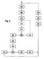
- FIG. 2 is a flowchart of a method for determining a course of a traffic lane traveled by a vehicle, such as from a lane as in FIG Fig. 1 shown device can be executed.
- step 200 of the method first a position of the vehicle is detected, e.g. by being queried by an existing navigation system.
- step 202 the beginning of a current lane segment is determined based on the detected position and digital map data of the lane, which is also e.g. can be obtained from the existing navigation system and, for example, be taken from a digital map contained in a DVD drive or on a hard drive of the navigation system.
- FIG. 3 Figure 4 is a schematic plan view of a lane 302 in the form stored in the form of digital mapping data in a conventional digital map.
- the digital mapping data includes a series of nodes 328-338 along which lane 302 passes.
- the starting point defined by the digital map is arbitrary but fixed and in the present case can coincide, for example, with the interpolation point 328.
- the navigation system using the digital mapping data determines the current longitudinal position and orientation of the vehicle 300 on the roadway 302, eg, by determining the last behind-the-vehicle intersection 333 and the distance 308 traveled from that intersection 333 which are part of the total distance 304 to the next in front of the vehicle support point 334 represents.
- the position of the vehicle 300 for example, the position of the center 310 of the rear axle of the vehicle 300 is considered.
- the beginning of the current driving lane segment can be determined, for example, in step 202 as the position of the last interpolation point 333 behind the vehicle.
- a first 333, second 334 and third 335 interpolation point along the lane is first determined in step 210, for which purpose, starting with the beginning 333 determined in step 202, further progressing on the digital mapping data progressing in the direction of travel Support points 334, 335 are removed.
- s k is intended to designate the path from the starting point 330 of the route calculation to the k th interpolation point.
- the derivative of the local curvature after the travel distance in the interval between the first 333 and third 335 interpolation point is substantially constant. That is, the curvature course between the first 333 and second 334 support point also continues beyond the second support point 334 to at least the third support point 335 substantially.
- a branch is made to step 242 where the data of the second interpolation point 334 is replaced by the data of the third interpolation point 335, and the data of the third interpolation point 335 is replaced by the data of the immediately following nearest interpolation point 336.
- Steps 242, 212, 214 and the branching step 240 are repeated until a support point is found as a second support point, at which the first difference ⁇ ' 1 has a larger amount than the threshold value, the curvature course along the lane therefore shows a substantial change.
- branching step 240 branches to step 218.
- step 218 a fourth support point along the lane 302 is then determined from the digital mapping data, which is still beyond the third in the direction of travel of the vehicle 300 Support point 335 is located. Expediently, this is the support point 336 immediately following the third support point 335 in the direction of travel. Like the first to third support points 333-335, the fourth support point 336 also includes an associated distance and lane curvature value of the lane 302 at the fourth support point 336.
- step 220 a third curvature change ⁇ ' 3 per lane distance between the third 335 5 and fourth 336 interpolation points is calculated, in the same way as in step 212 for the first 333 and second 334 interpolation points, and for the second 334 and third 335 interpolation points has happened.
- the second difference ⁇ ' 2 is compared with a predetermined threshold value which, for example, is identical to the threshold value used in branching step 240. If the second difference ⁇ ' 1 has a smaller or equal magnitude than the threshold value, it is concluded that the derivative of the local curvature after the distance in the interval between the third 335 and fourth 336 interpolation point is substantially constant. That is, the curvature course between the second 334 and third 335 support point is also continued beyond the third support point 335 to at least the fourth support point 336 substantially. In this case, a branch is made to step 216 where the end of the current lane segment is set at the third interpolation point 335. This determines the limits of the current driving lane segment.
- a predetermined threshold value which, for example, is identical to the threshold value used in branching step 240.
- FIG. 4 shows a diagram of the curvature of a lane over the distance along the lane. Along a horizontal axis 400, the distance, and carried along a vertical axis 402, the local curvature. (In the Fig. 3 indicated radii of curvature R are purely illustrative there and have no relation to the curvature values in Fig.
- the method is based on the assumption that the derivative of the curvature 404 is at a point within the interval between the second and third interpolation point changes abruptly, but at the second and third interpolation point is in each case constant.
- This case is in Fig. 4 respectively between the support points 328 and 329, 331 and 332 and 336 and 337 shown.
- the first to fourth interpolation points lie at the interpolation points 335 to 338.
- the method branches branching step 244 to step 226.
- an additional interpolation point 406 between the second 336 and third 337 interpolation points is determined such that an extrapolation 408 of the first curvature change per lane distance (between the first 335 and second 336 interpolation point) and an extrapolation 410 of the third curvature change per lane distance (between the first 335 and second 336 interpolation point) third 337 and fourth 338 support points) at the additional support point 406 result in a same roadway curvature. In Fig. 4 this is the intersection 406 of the two extrapolation lines 408, 410.
- the boundary at which the current lane segment ends is set at the additional interpolation point 406 between the second 336 and third 337 interpolation points.
- step 206 track information for detecting the traffic lane in the current traffic lane segment is recorded with a video-based lane information device, which describes a curvature profile of the traffic lane in front of the vehicle.
- the lane information is adaptively filtered in response to the class of the current lane segment assigned in step 204.
- filtering e.g. a Kalman filter with multi-model approach suitable.
- the model of the filter is adjusted or switched between different models.
- filtering is performed with a model assumption of linear change in local curvature over the distance when the current lane segment is a transition arc, filtering with a model assumption of constant curvature over the distance if the current lane segment is a circular arc, and filtering with a model assumption that the local curvature is zero throughout the lane segment if the current lane segment is a straight line.
- step 208 the method begins again at step 200 so that the traveled lane is continuously divided into segments.
- FIG. 5 shows a diagram of a time course of curvature of a lane, which is traveled by a vehicle. Over a time axis 500, along a vertical axis of curvature 402, a map-based curve 502 determined from the digital mapping data in the manner described above is plotted. A constant speed of the vehicle is assumed, so that a linear change of the curvature with the time 500 also corresponds to a linear change of the curvature over the distance. The traveled distance was subdivided into lane segments 512-518 in the manner described above, with segments 510 and 518 assigned the class of the straight line, segment 514 the class of circular arcs and segments 512 and 516 the class of transitional arches (clothoids).
- video-based lane information 504 are also plotted, which also describe the curvature of the same lane line.
- the video-based lane information 504 shows oscillations 520, e.g. by measurement errors of the video-based method with which the lane information was recorded, and / or caused by missing, hidden or inaccurate lane markings.
- filtered lane information 506 obtained from the video-based lane information 504 through adaptive, model-based filtering, wherein different model assumptions are made in each lane segment 510-518, depending on the class assigned to the respective lane segment.
- the oscillations 520 are the underlying video based Filter information 504 suppressed, so that the filtered lane information 506 reflect the curvature of the real lane with increased precision.
Landscapes
- Engineering & Computer Science (AREA)
- Physics & Mathematics (AREA)
- General Physics & Mathematics (AREA)
- Multimedia (AREA)
- Theoretical Computer Science (AREA)
- Traffic Control Systems (AREA)
- Navigation (AREA)
- Image Analysis (AREA)
Claims (10)
- Procédé de détermination de l'évolution de la trajectoire (302) parcourue par un véhicule (300), le procédé comportant les étapes suivantes :- saisir (200) une position du véhicule (300),- déterminer (202-226) un segment en cours de la trajectoire de déplacement sur base de la position saisie et de données numériques (112) de cartographie de la trajectoire de déplacement (302),- sur base des données numériques (112) de cartographie, définir (204) la classe du segment en cours de la trajectoire de déplacement qui correspond à l'évolution de la courbure de la trajectoire de déplacement (302) dans le segment en cours de la trajectoire de déplacement,- saisir (206) des informations de trajectoire pour détecter la trajectoire de déplacement (302) dans le segment en cours de la trajectoire de déplacement et- filtrer (208) de manière adaptative les informations de trajectoire en fonction de la classe du segment en cours de la trajectoire de déplacement, différents algorithmes de filtrage basés sur modèles étant utilisés en fonction de la classe du segment en cours de la trajectoire de déplacement et provenant d'un modèle différent, adapté à la classe du segment de la trajectoire de déplacement, d'une évolution de la trajectoire de déplacement.
- Procédé selon la revendication 1, dans lequel la détermination (202-226) du segment en cours de la trajectoire de déplacement comprend les étapes suivantes :- à partir des données numériques (112) de cartographie, déterminer (210) sur la trajectoire de déplacement (302) un premier point d'appui (333), un deuxième point d'appui (334) et un troisième point d'appui (335) sur lesquels la trajectoire de déplacement (302) présente respectivement une première courbure (κ1) de la chaussée, une deuxième courbure (κ2) de la chaussée et une troisième courbure (κ3) de la chaussée,- calculer (212) une première modification de la courbure pour le segment de trajectoire de déplacement situé entre le premier point d'appui (333) et le deuxième point d'appui (334) et une deuxième modification de courbure pour le segment de trajectoire de déplacement situé entre le deuxième point d'appui (334) et le troisième point d'appui (335),- déterminer (214) une première différence entre la première et la deuxième modification de courbure pour chaque segment de trajectoire de déplacement et- définir (216) une limite du segment en cours de la trajectoire de déplacement au niveau du deuxième point d'appui si la première différence dépasse une valeur de seuil.
- Procédé selon la revendication 2, dans lequel la détermination (202, 226) du segment en cours de la trajectoire de déplacement comprend en outre les étapes qui consistent à :- à partir des données numériques (112) de cartographie, déterminer (218) sur la trajectoire de déplacement (302) un quatrième point d'appui sur lequel la trajectoire de déplacement présente une quatrième courbure de la chaussée,- calculer (220) une troisième modification de la courbure pour la partie de la trajectoire de déplacement située entre le troisième et le quatrième point d'appui,- déterminer (222) une deuxième différence entre la deuxième et la troisième différence de courbure sur chaque partie de trajectoire de déplacement et- définir (224) la limite du segment en cours de la trajectoire de déplacement au niveau d'un point d'appui supplémentaire situé entre le deuxième et le troisième point d'appui si la première et la deuxième différence dépassent la valeur de seuil.
- Procédé selon la revendication 3, dans lequel pour déterminer (202-226) le segment en cours de trajectoire de déplacement, une étape de détermination (226) du point d'appui supplémentaire est en outre exécutée de telle sorte qu'une extrapolation de la première modification de courbure pour chaque partie de trajectoire de déplacement et une extrapolation de la troisième modification de courbure pour chaque partie de trajectoire de déplacement donnent une même courbure de la chaussée au point d'appui supplémentaire.
- Procédé selon l'une des revendications précédentes, dans lequel la détermination de la classe du segment en cours de la trajectoire de déplacement s'effectue à partir de plusieurs classes de segment qui comprennent au moins l'un des éléments suivants :- une classe de segments rectilignes,- une classe de segments en arc de cercle et- une classe de segments d'arc de transition.
- Procédé selon l'une des revendications précédentes, dans lequel la saisie des informations de trajectoire s'effectue dans une zone située en avant du véhicule (300).
- Procédé selon l'une des revendications précédentes, dans lequel la saisie des informations de trajectoire de déplacement s'effectue au moyen de détecteurs d'ambiance, en particulier de détecteurs vidéo et/ou de détecteurs radar.
- Procédé selon l'une des revendications précédentes, dans lequel la saisie de la position et/ou la saisie des informations de trajectoire s'effectue au moyen d'un dispositif de localisation (102) basé sur satellites.
- Produit de programme informatique doté d'indications de programme qui sont conservées sur un support lisible par machine, en vue de l'exécution du procédé selon au moins l'une des revendications précédentes lorsque les indications de programme sont exécutées sur un ordinateur ou un dispositif de commande (100).
- Ensemble (100) de détermination de l'évolution d'une trajectoire de déplacement (302) parcourue par un véhicule (300), l'ensemble comprenant :- un dispositif (102) de saisie de position qui saisit une position du véhicule (300),- un dispositif (104) de détermination de segments de trajectoire de déplacement qui détermine un segment en cours de la trajectoire de déplacement sur base de la position saisie et de données numériques (112) de cartographie de la trajectoire de déplacement (302),- un classificateur (106) de segments de trajectoire de déplacement qui définit sur base des données numériques (112) de cartographie la classe du segment en cours de la trajectoire de déplacement en correspondance à l'évolution de courbure de la trajectoire de déplacement (302) dans le segment en cours de la trajectoire de déplacement,- un dispositif (108) d'informations sur la trajectoire qui saisit des informations sur la trajectoire en vue de détecter la trajectoire de déplacement (302) dans le segment en cours de la trajectoire de déplacement et- un filtre (110) d'informations sur la trajectoire qui filtre de manière adaptative les informations de trajectoire en fonction de la classe du segment en cours de la trajectoire de déplacement, différents algorithmes de filtrage basés sur modèles étant utilisés en fonction de la classe du segment en cours de la trajectoire de déplacement et fournissant une évolution de la trajectoire de déplacement à partir d'un modèle différent, adapté à la classe de segment de trajectoire de déplacement.
Applications Claiming Priority (1)
| Application Number | Priority Date | Filing Date | Title |
|---|---|---|---|
| DE102008042538A DE102008042538A1 (de) | 2008-10-01 | 2008-10-01 | Verfahren und Vorrichtung zum Ermitteln eines Fahrspurverlaufs |
Publications (2)
| Publication Number | Publication Date |
|---|---|
| EP2172826A1 EP2172826A1 (fr) | 2010-04-07 |
| EP2172826B1 true EP2172826B1 (fr) | 2011-12-07 |
Family
ID=41606730
Family Applications (1)
| Application Number | Title | Priority Date | Filing Date |
|---|---|---|---|
| EP09167913A Not-in-force EP2172826B1 (fr) | 2008-10-01 | 2009-08-14 | Dispositif et procédé destinés à déterminer un parcours de voie de circulation |
Country Status (3)
| Country | Link |
|---|---|
| EP (1) | EP2172826B1 (fr) |
| AT (1) | ATE536578T1 (fr) |
| DE (1) | DE102008042538A1 (fr) |
Families Citing this family (4)
| Publication number | Priority date | Publication date | Assignee | Title |
|---|---|---|---|---|
| FR3033912B1 (fr) | 2015-03-18 | 2018-06-15 | Valeo Schalter Und Sensoren Gmbh | Procede d'estimation de parametres geometriques representatifs de la forme d'une route, systeme d'estimation de tels parametres et vehicule automobile equipe d'un tel systeme |
| DE102019008368A1 (de) * | 2019-12-02 | 2021-06-02 | Daimler Ag | Verfahren zum Betrieb eines Fahrzeugs und Vorrichtung zur Durchführung des Verfahrens |
| CN112578425A (zh) * | 2020-12-25 | 2021-03-30 | 北京天润海图科技有限公司 | 一种室外轨道电子地图生成方法 |
| CN116429127A (zh) * | 2023-03-06 | 2023-07-14 | 智道网联科技(北京)有限公司 | 一种车道线平滑度检测方法、装置、电子设备和存储介质 |
Family Cites Families (6)
| Publication number | Priority date | Publication date | Assignee | Title |
|---|---|---|---|---|
| AU2929201A (en) | 2000-01-05 | 2001-07-16 | Johns Hopkins University, The | Global positioning system roadside integrated precision positioning system |
| JP3795299B2 (ja) * | 2000-04-07 | 2006-07-12 | 本田技研工業株式会社 | 車両制御装置 |
| JP3521860B2 (ja) * | 2000-10-02 | 2004-04-26 | 日産自動車株式会社 | 車両の走行路認識装置 |
| US6718259B1 (en) * | 2002-10-02 | 2004-04-06 | Hrl Laboratories, Llc | Adaptive Kalman filter method for accurate estimation of forward path geometry of an automobile |
| DE10311241B4 (de) | 2003-03-14 | 2021-05-27 | Robert Bosch Gmbh | Verfahren und Einrichtung für die Spurführung eines Fahrzeugs |
| JP4392389B2 (ja) * | 2005-06-27 | 2009-12-24 | 本田技研工業株式会社 | 車両及び車線認識装置 |
-
2008
- 2008-10-01 DE DE102008042538A patent/DE102008042538A1/de not_active Withdrawn
-
2009
- 2009-08-14 EP EP09167913A patent/EP2172826B1/fr not_active Not-in-force
- 2009-08-14 AT AT09167913T patent/ATE536578T1/de active
Also Published As
| Publication number | Publication date |
|---|---|
| ATE536578T1 (de) | 2011-12-15 |
| EP2172826A1 (fr) | 2010-04-07 |
| DE102008042538A1 (de) | 2010-04-08 |
Similar Documents
| Publication | Publication Date | Title |
|---|---|---|
| EP3584663B1 (fr) | Procédé de guidage transversal automatique d'un véhicule suiveur dans un peloton de véhicules | |
| DE102013105046B4 (de) | Zielspurauswahlverfahren mittels Navigationseingabe in Straßenwechselszenarien | |
| DE102016213817B4 (de) | Verfahren, Vorrichtung und computerlesbares Speichermedium mit Instruktionen zur Bestimmung der lateralen Position eines Fahrzeuges relativ zu den Fahrstreifen einer Fahrbahn | |
| DE102006040334A1 (de) | Verfahren für die Spurerfassung mit einem Fahrerassistenzsystem und Fahrerassistenzsystem | |
| EP2594461B1 (fr) | Procédé de détection d'une place de stationnement pour un véhicule automobile, système d'aide au stationnement et véhicule automobile équipé d'un système d'aide au stationnement | |
| EP3465088B1 (fr) | Procédé, dispositif et support d'informations lisible par ordinateur comprenant des instructions pour déterminer la position latérale d'un véhicule par rapport aux bandes de circulation d'une chaussée | |
| DE102019100034A1 (de) | Autonome lenksteuerung | |
| EP2746725A2 (fr) | Procédé et dispositif de commande de mise à disposition d'un tracé de route à suivre. | |
| DE102015210015A1 (de) | Verfahren und Vorrichtung zur Positionsbestimmung eines Fahrzeugs | |
| EP0915350A2 (fr) | Dispositif pour déterminer des données indicatives de l'évolution des voies de circulation | |
| WO2005039957A1 (fr) | Procede d'assistance au conducteur et dispositif fonctionnant sur la base d'informations de voies de circulation | |
| EP2447126A2 (fr) | Procédé et dispositif de détermination d'une voie de circulation plausible pour l'acheminement d'un véhicule ainsi que véhicule automobile | |
| EP3898368B1 (fr) | Procédé et système servant à déterminer une trajectoire corrigée d'un véhicule | |
| WO2009013052A2 (fr) | Procédé et dispositif de détection de voie au moyen d'un système d'aide à la conduite | |
| DE102004028404A1 (de) | Verfahren zur Schätzung des Verlaufs einer Fahrspur eines Kraftfahrzeuges | |
| DE102013220487B4 (de) | Fahrspurerkennungssystem umd Spurhaltesystem | |
| EP2172826B1 (fr) | Dispositif et procédé destinés à déterminer un parcours de voie de circulation | |
| EP2654027B1 (fr) | Procédé d'émission d'un avertissement avant un dépassement | |
| DE112018002372T5 (de) | Informationsverwaltungsvorrichtung | |
| DE102010062322A1 (de) | Verfahren zur Kalibrierung | |
| DE102009046855A1 (de) | Verfahren und Navigationsgerät zum Bereitstellen von Zusatzdaten in einer digitalen Straßenkarte | |
| DE102006040333A1 (de) | Verfahren für die Spurerfassung mit einem Fahrerassistenzsystem eines Fahrzeugs | |
| DE112020007559B4 (de) | Fahrassistenzregelungsvorrichtung und Fahrassistenzregelungsverfahren | |
| DE102013217061B4 (de) | Spurgenaue Positionierung eines Fahrzeugs | |
| DE102024102161A1 (de) | Autonomes fahrzeug und verfahren zum steuern desselben |
Legal Events
| Date | Code | Title | Description |
|---|---|---|---|
| PUAI | Public reference made under article 153(3) epc to a published international application that has entered the european phase |
Free format text: ORIGINAL CODE: 0009012 |
|
| AK | Designated contracting states |
Kind code of ref document: A1 Designated state(s): AT BE BG CH CY CZ DE DK EE ES FI FR GB GR HR HU IE IS IT LI LT LU LV MC MK MT NL NO PL PT RO SE SI SK SM TR |
|
| 17P | Request for examination filed |
Effective date: 20101007 |
|
| 17Q | First examination report despatched |
Effective date: 20101103 |
|
| GRAP | Despatch of communication of intention to grant a patent |
Free format text: ORIGINAL CODE: EPIDOSNIGR1 |
|
| GRAS | Grant fee paid |
Free format text: ORIGINAL CODE: EPIDOSNIGR3 |
|
| GRAA | (expected) grant |
Free format text: ORIGINAL CODE: 0009210 |
|
| AK | Designated contracting states |
Kind code of ref document: B1 Designated state(s): AT BE BG CH CY CZ DE DK EE ES FI FR GB GR HR HU IE IS IT LI LT LU LV MC MK MT NL NO PL PT RO SE SI SK SM TR |
|
| REG | Reference to a national code |
Ref country code: GB Ref legal event code: FG4D Free format text: NOT ENGLISH |
|
| REG | Reference to a national code |
Ref country code: CH Ref legal event code: EP |
|
| REG | Reference to a national code |
Ref country code: IE Ref legal event code: FG4D Free format text: LANGUAGE OF EP DOCUMENT: GERMAN |
|
| REG | Reference to a national code |
Ref country code: DE Ref legal event code: R096 Ref document number: 502009002113 Country of ref document: DE Effective date: 20120308 |
|
| REG | Reference to a national code |
Ref country code: NL Ref legal event code: VDEP Effective date: 20111207 |
|
| PG25 | Lapsed in a contracting state [announced via postgrant information from national office to epo] |
Ref country code: LT Free format text: LAPSE BECAUSE OF FAILURE TO SUBMIT A TRANSLATION OF THE DESCRIPTION OR TO PAY THE FEE WITHIN THE PRESCRIBED TIME-LIMIT Effective date: 20111207 Ref country code: NO Free format text: LAPSE BECAUSE OF FAILURE TO SUBMIT A TRANSLATION OF THE DESCRIPTION OR TO PAY THE FEE WITHIN THE PRESCRIBED TIME-LIMIT Effective date: 20120307 |
|
| LTIE | Lt: invalidation of european patent or patent extension |
Effective date: 20111207 |
|
| PG25 | Lapsed in a contracting state [announced via postgrant information from national office to epo] |
Ref country code: NL Free format text: LAPSE BECAUSE OF FAILURE TO SUBMIT A TRANSLATION OF THE DESCRIPTION OR TO PAY THE FEE WITHIN THE PRESCRIBED TIME-LIMIT Effective date: 20111207 Ref country code: SI Free format text: LAPSE BECAUSE OF FAILURE TO SUBMIT A TRANSLATION OF THE DESCRIPTION OR TO PAY THE FEE WITHIN THE PRESCRIBED TIME-LIMIT Effective date: 20111207 Ref country code: SE Free format text: LAPSE BECAUSE OF FAILURE TO SUBMIT A TRANSLATION OF THE DESCRIPTION OR TO PAY THE FEE WITHIN THE PRESCRIBED TIME-LIMIT Effective date: 20111207 Ref country code: GR Free format text: LAPSE BECAUSE OF FAILURE TO SUBMIT A TRANSLATION OF THE DESCRIPTION OR TO PAY THE FEE WITHIN THE PRESCRIBED TIME-LIMIT Effective date: 20120308 Ref country code: LV Free format text: LAPSE BECAUSE OF FAILURE TO SUBMIT A TRANSLATION OF THE DESCRIPTION OR TO PAY THE FEE WITHIN THE PRESCRIBED TIME-LIMIT Effective date: 20111207 Ref country code: HR Free format text: LAPSE BECAUSE OF FAILURE TO SUBMIT A TRANSLATION OF THE DESCRIPTION OR TO PAY THE FEE WITHIN THE PRESCRIBED TIME-LIMIT Effective date: 20111207 |
|
| PG25 | Lapsed in a contracting state [announced via postgrant information from national office to epo] |
Ref country code: CY Free format text: LAPSE BECAUSE OF FAILURE TO SUBMIT A TRANSLATION OF THE DESCRIPTION OR TO PAY THE FEE WITHIN THE PRESCRIBED TIME-LIMIT Effective date: 20111207 |
|
| REG | Reference to a national code |
Ref country code: IE Ref legal event code: FD4D |
|
| PG25 | Lapsed in a contracting state [announced via postgrant information from national office to epo] |
Ref country code: SK Free format text: LAPSE BECAUSE OF FAILURE TO SUBMIT A TRANSLATION OF THE DESCRIPTION OR TO PAY THE FEE WITHIN THE PRESCRIBED TIME-LIMIT Effective date: 20111207 Ref country code: EE Free format text: LAPSE BECAUSE OF FAILURE TO SUBMIT A TRANSLATION OF THE DESCRIPTION OR TO PAY THE FEE WITHIN THE PRESCRIBED TIME-LIMIT Effective date: 20111207 Ref country code: BG Free format text: LAPSE BECAUSE OF FAILURE TO SUBMIT A TRANSLATION OF THE DESCRIPTION OR TO PAY THE FEE WITHIN THE PRESCRIBED TIME-LIMIT Effective date: 20120307 Ref country code: CZ Free format text: LAPSE BECAUSE OF FAILURE TO SUBMIT A TRANSLATION OF THE DESCRIPTION OR TO PAY THE FEE WITHIN THE PRESCRIBED TIME-LIMIT Effective date: 20111207 Ref country code: IS Free format text: LAPSE BECAUSE OF FAILURE TO SUBMIT A TRANSLATION OF THE DESCRIPTION OR TO PAY THE FEE WITHIN THE PRESCRIBED TIME-LIMIT Effective date: 20120407 Ref country code: IE Free format text: LAPSE BECAUSE OF FAILURE TO SUBMIT A TRANSLATION OF THE DESCRIPTION OR TO PAY THE FEE WITHIN THE PRESCRIBED TIME-LIMIT Effective date: 20111207 |
|
| PG25 | Lapsed in a contracting state [announced via postgrant information from national office to epo] |
Ref country code: PT Free format text: LAPSE BECAUSE OF FAILURE TO SUBMIT A TRANSLATION OF THE DESCRIPTION OR TO PAY THE FEE WITHIN THE PRESCRIBED TIME-LIMIT Effective date: 20120409 Ref country code: RO Free format text: LAPSE BECAUSE OF FAILURE TO SUBMIT A TRANSLATION OF THE DESCRIPTION OR TO PAY THE FEE WITHIN THE PRESCRIBED TIME-LIMIT Effective date: 20111207 Ref country code: PL Free format text: LAPSE BECAUSE OF FAILURE TO SUBMIT A TRANSLATION OF THE DESCRIPTION OR TO PAY THE FEE WITHIN THE PRESCRIBED TIME-LIMIT Effective date: 20111207 |
|
| PLBE | No opposition filed within time limit |
Free format text: ORIGINAL CODE: 0009261 |
|
| STAA | Information on the status of an ep patent application or granted ep patent |
Free format text: STATUS: NO OPPOSITION FILED WITHIN TIME LIMIT |
|
| PG25 | Lapsed in a contracting state [announced via postgrant information from national office to epo] |
Ref country code: DK Free format text: LAPSE BECAUSE OF FAILURE TO SUBMIT A TRANSLATION OF THE DESCRIPTION OR TO PAY THE FEE WITHIN THE PRESCRIBED TIME-LIMIT Effective date: 20111207 |
|
| 26N | No opposition filed |
Effective date: 20120910 |
|
| REG | Reference to a national code |
Ref country code: DE Ref legal event code: R097 Ref document number: 502009002113 Country of ref document: DE Effective date: 20120910 |
|
| BERE | Be: lapsed |
Owner name: ROBERT BOSCH G.M.B.H. Effective date: 20120831 |
|
| PG25 | Lapsed in a contracting state [announced via postgrant information from national office to epo] |
Ref country code: MC Free format text: LAPSE BECAUSE OF NON-PAYMENT OF DUE FEES Effective date: 20120831 |
|
| PG25 | Lapsed in a contracting state [announced via postgrant information from national office to epo] |
Ref country code: ES Free format text: LAPSE BECAUSE OF FAILURE TO SUBMIT A TRANSLATION OF THE DESCRIPTION OR TO PAY THE FEE WITHIN THE PRESCRIBED TIME-LIMIT Effective date: 20120318 |
|
| REG | Reference to a national code |
Ref country code: FR Ref legal event code: ST Effective date: 20130430 |
|
| PG25 | Lapsed in a contracting state [announced via postgrant information from national office to epo] |
Ref country code: BE Free format text: LAPSE BECAUSE OF NON-PAYMENT OF DUE FEES Effective date: 20120831 |
|
| PG25 | Lapsed in a contracting state [announced via postgrant information from national office to epo] |
Ref country code: FI Free format text: LAPSE BECAUSE OF FAILURE TO SUBMIT A TRANSLATION OF THE DESCRIPTION OR TO PAY THE FEE WITHIN THE PRESCRIBED TIME-LIMIT Effective date: 20111207 |
|
| PG25 | Lapsed in a contracting state [announced via postgrant information from national office to epo] |
Ref country code: FR Free format text: LAPSE BECAUSE OF NON-PAYMENT OF DUE FEES Effective date: 20120831 |
|
| PG25 | Lapsed in a contracting state [announced via postgrant information from national office to epo] |
Ref country code: MT Free format text: LAPSE BECAUSE OF FAILURE TO SUBMIT A TRANSLATION OF THE DESCRIPTION OR TO PAY THE FEE WITHIN THE PRESCRIBED TIME-LIMIT Effective date: 20111207 |
|
| REG | Reference to a national code |
Ref country code: CH Ref legal event code: PL |
|
| PG25 | Lapsed in a contracting state [announced via postgrant information from national office to epo] |
Ref country code: LI Free format text: LAPSE BECAUSE OF NON-PAYMENT OF DUE FEES Effective date: 20130831 Ref country code: CH Free format text: LAPSE BECAUSE OF NON-PAYMENT OF DUE FEES Effective date: 20130831 Ref country code: TR Free format text: LAPSE BECAUSE OF FAILURE TO SUBMIT A TRANSLATION OF THE DESCRIPTION OR TO PAY THE FEE WITHIN THE PRESCRIBED TIME-LIMIT Effective date: 20111207 |
|
| PG25 | Lapsed in a contracting state [announced via postgrant information from national office to epo] |
Ref country code: SM Free format text: LAPSE BECAUSE OF FAILURE TO SUBMIT A TRANSLATION OF THE DESCRIPTION OR TO PAY THE FEE WITHIN THE PRESCRIBED TIME-LIMIT Effective date: 20111207 Ref country code: LU Free format text: LAPSE BECAUSE OF NON-PAYMENT OF DUE FEES Effective date: 20120814 |
|
| PG25 | Lapsed in a contracting state [announced via postgrant information from national office to epo] |
Ref country code: HU Free format text: LAPSE BECAUSE OF FAILURE TO SUBMIT A TRANSLATION OF THE DESCRIPTION OR TO PAY THE FEE WITHIN THE PRESCRIBED TIME-LIMIT Effective date: 20090814 |
|
| PG25 | Lapsed in a contracting state [announced via postgrant information from national office to epo] |
Ref country code: MK Free format text: LAPSE BECAUSE OF FAILURE TO SUBMIT A TRANSLATION OF THE DESCRIPTION OR TO PAY THE FEE WITHIN THE PRESCRIBED TIME-LIMIT Effective date: 20111207 |
|
| REG | Reference to a national code |
Ref country code: AT Ref legal event code: MM01 Ref document number: 536578 Country of ref document: AT Kind code of ref document: T Effective date: 20140814 |
|
| PG25 | Lapsed in a contracting state [announced via postgrant information from national office to epo] |
Ref country code: AT Free format text: LAPSE BECAUSE OF NON-PAYMENT OF DUE FEES Effective date: 20140814 |
|
| PGFP | Annual fee paid to national office [announced via postgrant information from national office to epo] |
Ref country code: GB Payment date: 20200825 Year of fee payment: 12 |
|
| PGFP | Annual fee paid to national office [announced via postgrant information from national office to epo] |
Ref country code: IT Payment date: 20200831 Year of fee payment: 12 |
|
| PGFP | Annual fee paid to national office [announced via postgrant information from national office to epo] |
Ref country code: DE Payment date: 20201021 Year of fee payment: 12 |
|
| REG | Reference to a national code |
Ref country code: DE Ref legal event code: R119 Ref document number: 502009002113 Country of ref document: DE |
|
| GBPC | Gb: european patent ceased through non-payment of renewal fee |
Effective date: 20210814 |
|
| PG25 | Lapsed in a contracting state [announced via postgrant information from national office to epo] |
Ref country code: IT Free format text: LAPSE BECAUSE OF NON-PAYMENT OF DUE FEES Effective date: 20210814 Ref country code: GB Free format text: LAPSE BECAUSE OF NON-PAYMENT OF DUE FEES Effective date: 20210814 Ref country code: DE Free format text: LAPSE BECAUSE OF NON-PAYMENT OF DUE FEES Effective date: 20220301 |