EP2172995A1 - Lithiumionensekundärbatterie - Google Patents
Lithiumionensekundärbatterie Download PDFInfo
- Publication number
- EP2172995A1 EP2172995A1 EP08790232A EP08790232A EP2172995A1 EP 2172995 A1 EP2172995 A1 EP 2172995A1 EP 08790232 A EP08790232 A EP 08790232A EP 08790232 A EP08790232 A EP 08790232A EP 2172995 A1 EP2172995 A1 EP 2172995A1
- Authority
- EP
- European Patent Office
- Prior art keywords
- negative electrode
- active material
- lithium
- opposing portion
- electrode active
- Prior art date
- Legal status (The legal status is an assumption and is not a legal conclusion. Google has not performed a legal analysis and makes no representation as to the accuracy of the status listed.)
- Withdrawn
Links
Images


Classifications
-
- H—ELECTRICITY
- H01—ELECTRIC ELEMENTS
- H01M—PROCESSES OR MEANS, e.g. BATTERIES, FOR THE DIRECT CONVERSION OF CHEMICAL ENERGY INTO ELECTRICAL ENERGY
- H01M10/00—Secondary cells; Manufacture thereof
- H01M10/05—Accumulators with non-aqueous electrolyte
- H01M10/052—Li-accumulators
- H01M10/0525—Rocking-chair batteries, i.e. batteries with lithium insertion or intercalation in both electrodes; Lithium-ion batteries
-
- H—ELECTRICITY
- H01—ELECTRIC ELEMENTS
- H01M—PROCESSES OR MEANS, e.g. BATTERIES, FOR THE DIRECT CONVERSION OF CHEMICAL ENERGY INTO ELECTRICAL ENERGY
- H01M10/00—Secondary cells; Manufacture thereof
- H01M10/36—Accumulators not provided for in groups H01M10/05-H01M10/34
- H01M10/38—Construction or manufacture
-
- H—ELECTRICITY
- H01—ELECTRIC ELEMENTS
- H01M—PROCESSES OR MEANS, e.g. BATTERIES, FOR THE DIRECT CONVERSION OF CHEMICAL ENERGY INTO ELECTRICAL ENERGY
- H01M4/00—Electrodes
- H01M4/02—Electrodes composed of, or comprising, active material
- H01M4/04—Processes of manufacture in general
- H01M4/0402—Methods of deposition of the material
- H01M4/0421—Methods of deposition of the material involving vapour deposition
-
- H—ELECTRICITY
- H01—ELECTRIC ELEMENTS
- H01M—PROCESSES OR MEANS, e.g. BATTERIES, FOR THE DIRECT CONVERSION OF CHEMICAL ENERGY INTO ELECTRICAL ENERGY
- H01M4/00—Electrodes
- H01M4/02—Electrodes composed of, or comprising, active material
- H01M4/13—Electrodes for accumulators with non-aqueous electrolyte, e.g. for lithium-accumulators; Processes of manufacture thereof
- H01M4/131—Electrodes based on mixed oxides or hydroxides, or on mixtures of oxides or hydroxides, e.g. LiCoOx
-
- H—ELECTRICITY
- H01—ELECTRIC ELEMENTS
- H01M—PROCESSES OR MEANS, e.g. BATTERIES, FOR THE DIRECT CONVERSION OF CHEMICAL ENERGY INTO ELECTRICAL ENERGY
- H01M4/00—Electrodes
- H01M4/02—Electrodes composed of, or comprising, active material
- H01M4/13—Electrodes for accumulators with non-aqueous electrolyte, e.g. for lithium-accumulators; Processes of manufacture thereof
- H01M4/134—Electrodes based on metals, Si or alloys
-
- H—ELECTRICITY
- H01—ELECTRIC ELEMENTS
- H01M—PROCESSES OR MEANS, e.g. BATTERIES, FOR THE DIRECT CONVERSION OF CHEMICAL ENERGY INTO ELECTRICAL ENERGY
- H01M4/00—Electrodes
- H01M4/02—Electrodes composed of, or comprising, active material
- H01M4/13—Electrodes for accumulators with non-aqueous electrolyte, e.g. for lithium-accumulators; Processes of manufacture thereof
- H01M4/139—Processes of manufacture
- H01M4/1391—Processes of manufacture of electrodes based on mixed oxides or hydroxides, or on mixtures of oxides or hydroxides, e.g. LiCoOx
-
- H—ELECTRICITY
- H01—ELECTRIC ELEMENTS
- H01M—PROCESSES OR MEANS, e.g. BATTERIES, FOR THE DIRECT CONVERSION OF CHEMICAL ENERGY INTO ELECTRICAL ENERGY
- H01M4/00—Electrodes
- H01M4/02—Electrodes composed of, or comprising, active material
- H01M4/13—Electrodes for accumulators with non-aqueous electrolyte, e.g. for lithium-accumulators; Processes of manufacture thereof
- H01M4/139—Processes of manufacture
- H01M4/1395—Processes of manufacture of electrodes based on metals, Si or alloys
-
- H—ELECTRICITY
- H01—ELECTRIC ELEMENTS
- H01M—PROCESSES OR MEANS, e.g. BATTERIES, FOR THE DIRECT CONVERSION OF CHEMICAL ENERGY INTO ELECTRICAL ENERGY
- H01M4/00—Electrodes
- H01M4/02—Electrodes composed of, or comprising, active material
- H01M4/36—Selection of substances as active materials, active masses, active liquids
- H01M4/38—Selection of substances as active materials, active masses, active liquids of elements or alloys
- H01M4/386—Silicon or alloys based on silicon
-
- H—ELECTRICITY
- H01—ELECTRIC ELEMENTS
- H01M—PROCESSES OR MEANS, e.g. BATTERIES, FOR THE DIRECT CONVERSION OF CHEMICAL ENERGY INTO ELECTRICAL ENERGY
- H01M4/00—Electrodes
- H01M4/02—Electrodes composed of, or comprising, active material
- H01M4/36—Selection of substances as active materials, active masses, active liquids
- H01M4/38—Selection of substances as active materials, active masses, active liquids of elements or alloys
- H01M4/387—Tin or alloys based on tin
-
- H—ELECTRICITY
- H01—ELECTRIC ELEMENTS
- H01M—PROCESSES OR MEANS, e.g. BATTERIES, FOR THE DIRECT CONVERSION OF CHEMICAL ENERGY INTO ELECTRICAL ENERGY
- H01M4/00—Electrodes
- H01M4/02—Electrodes composed of, or comprising, active material
- H01M4/36—Selection of substances as active materials, active masses, active liquids
- H01M4/48—Selection of substances as active materials, active masses, active liquids of inorganic oxides or hydroxides
- H01M4/485—Selection of substances as active materials, active masses, active liquids of inorganic oxides or hydroxides of mixed oxides or hydroxides for inserting or intercalating light metals, e.g. LiTi2O4 or LiTi2OxFy
-
- H—ELECTRICITY
- H01—ELECTRIC ELEMENTS
- H01M—PROCESSES OR MEANS, e.g. BATTERIES, FOR THE DIRECT CONVERSION OF CHEMICAL ENERGY INTO ELECTRICAL ENERGY
- H01M4/00—Electrodes
- H01M4/02—Electrodes composed of, or comprising, active material
- H01M4/36—Selection of substances as active materials, active masses, active liquids
- H01M4/58—Selection of substances as active materials, active masses, active liquids of inorganic compounds other than oxides or hydroxides, e.g. sulfides, selenides, tellurides, halogenides or LiCoFy; of polyanionic structures, e.g. phosphates, silicates or borates
-
- H—ELECTRICITY
- H01—ELECTRIC ELEMENTS
- H01M—PROCESSES OR MEANS, e.g. BATTERIES, FOR THE DIRECT CONVERSION OF CHEMICAL ENERGY INTO ELECTRICAL ENERGY
- H01M10/00—Secondary cells; Manufacture thereof
- H01M10/42—Methods or arrangements for servicing or maintenance of secondary cells or secondary half-cells
- H01M10/44—Methods for charging or discharging
- H01M10/446—Initial charging measures
-
- Y—GENERAL TAGGING OF NEW TECHNOLOGICAL DEVELOPMENTS; GENERAL TAGGING OF CROSS-SECTIONAL TECHNOLOGIES SPANNING OVER SEVERAL SECTIONS OF THE IPC; TECHNICAL SUBJECTS COVERED BY FORMER USPC CROSS-REFERENCE ART COLLECTIONS [XRACs] AND DIGESTS
- Y02—TECHNOLOGIES OR APPLICATIONS FOR MITIGATION OR ADAPTATION AGAINST CLIMATE CHANGE
- Y02E—REDUCTION OF GREENHOUSE GAS [GHG] EMISSIONS, RELATED TO ENERGY GENERATION, TRANSMISSION OR DISTRIBUTION
- Y02E60/00—Enabling technologies; Technologies with a potential or indirect contribution to GHG emissions mitigation
- Y02E60/10—Energy storage using batteries
-
- Y—GENERAL TAGGING OF NEW TECHNOLOGICAL DEVELOPMENTS; GENERAL TAGGING OF CROSS-SECTIONAL TECHNOLOGIES SPANNING OVER SEVERAL SECTIONS OF THE IPC; TECHNICAL SUBJECTS COVERED BY FORMER USPC CROSS-REFERENCE ART COLLECTIONS [XRACs] AND DIGESTS
- Y02—TECHNOLOGIES OR APPLICATIONS FOR MITIGATION OR ADAPTATION AGAINST CLIMATE CHANGE
- Y02P—CLIMATE CHANGE MITIGATION TECHNOLOGIES IN THE PRODUCTION OR PROCESSING OF GOODS
- Y02P70/00—Climate change mitigation technologies in the production process for final industrial or consumer products
- Y02P70/50—Manufacturing or production processes characterised by the final manufactured product
Definitions
- the present invention relates to a lithium ion secondary battery. More particularly, the present invention primarily relates to an improvement in the negative electrode.
- Lithium ion secondary batteries are being widely used as a power source for portable compact electronic devices such as, for example, cell phones, personal digital assistants (PDAs), notebook computers and camcorders, since they have a high capacity and a high energy density and facilitate miniaturization and weight reduction. With the recent trend toward increasing the functionality of portable compact electronic devices, demand is also growing for higher capacity in lithium ion secondary batteries.
- the alloy-based negative electrode active material is a material capable of absorbing lithium by being alloyed with lithium and reversibly absorbing and desorbing lithium.
- the alloy-based negative electrode active material for example, silicon, silicon-containing compounds, tin, tin-containing compounds and the like are known. Because the alloy-based negative electrode active material has a high discharge capacity, the use of such a negative electrode active material is effective in achieving higher capacity in lithium ion secondary batteries. Silicon, for example, has a theoretical discharge capacity of about 4199 mAh/g, which is about 11 times the theoretical discharge capacity of graphite.
- an alloy-based negative electrode active material expands because the crystal structure changes significantly when absorbing lithium ions, causing not only the current collector but also the negative electrode to deform. Along with this deformation, cracking of the negative electrode active material particles, separation of the negative electrode active material layer from the current collector, and the like occur. As a result, the electron conductivity between the current collector and the negative electrode active material layer decreases, leading to the deterioration of battery characteristics such as cycle characteristics.
- a proposal has been made in which a space for allowing such expansion when absorbing lithium ions to occur is provided in advance in such an alloy-based negative electrode active material layer.
- a negative electrode for a lithium secondary battery has been proposed in which, for example, a thin-film negative electrode active material layer made of an alloy-based negative electrode active material or an alloy containing an alloy-based negative electrode active material is formed in a prescribed pattern on a current collector made of a material that does not alloy with lithium (see, for example, Patent Document 1).
- a thin-film negative electrode active material layer is composed of a plurality of columns, and the columns are arranged in a staggered arrangement, a grid arrangement or the like with a gap between adjacent columns.
- Patent Document 2 attempts to increase the contact area of the interface between the current collector and the thin-film negative electrode active material layer and improve adhesion between the current collector and the thin-film negative electrode active material layer.
- Patent Document 2 when the negative electrode of Patent Document 2 is included in a lithium ion secondary battery, and the battery is subjected to an initial charge and discharge, because the current collector having the above-mentioned surface roughness is used, cracks are formed in the thin-film negative electrode active material layer, and the thin-film negative electrode active material layer is divided into a plurality of columns which exist apart from each other with a gap therebetween. Because the gap absorbs the expansion of the alloy-based negative electrode active material, separation of the thin-film negative electrode active material layer and the like are further prevented.
- a proposal is disclosed in which a partially nitrided silicon oxide powder represented by a composition formula: SiN x O y (where, 0 ⁇ x ⁇ 1.3, 0 ⁇ y ⁇ 1.5) is used as a negative electrode active material for a lithium ion secondary battery (see, for example, Patent Document 3).
- a negative electrode is produced in which a negative electrode active material layer containing the partially nitrided silicon oxide powder is formed on the current collector surface.
- a technique has also been proposed in which lithium foil is firmly attached to the surface of the negative electrode active material layer of a negative electrode with an auxiliary layer containing water-insoluble conductive particles interposed therebetween (see for example, Patent Document 4).
- the lithium in the lithium foil firmly attached to the negative electrode active material layer starts to disperse into the negative electrode active material layer at the point in time when an electrolyte is injected, and disperses throughout the negative electrode active material layer during the initial charge and discharge.
- Patent Document 4 also discloses a negative electrode active material layer configured to have a opposing portion opposing a positive electrode and a non-opposing portion not opposing the positive electrode, wherein the amount of lithium per unit area firmly attached to the non-opposing portion is increased relative to the amount of lithium per unit area firmly attached to the opposing portion.
- a method is used in which a lithium film is formed on the surface of a negative electrode active material layer by a vapor deposition method, such as a vacuum deposition method or ion plating method, so as to cause the negative electrode active material layer to absorb lithium that does not take part in charge and discharge reactions in an amount equivalent to its irreversible capacity.
- a vapor deposition method such as a vacuum deposition method or ion plating method
- Another method is also known in which a lithium film is formed, by a vapor deposition method, on the surface of a negative electrode active material layer formed by a vapor deposition method (see for example, Patent Document 5, paragraph 0037; and Patent Document 6).
- Patent Documents 5 and 6 do not disclose forming a lithium film on the non-opposing portion.
- the present inventors conducted in-depth studies to maintain the cycle characteristics of a lithium ion secondary battery including a negative electrode active material primarily containing silicon or tin at a high level for a long period of time. Specifically, they conducted studies to suppress expansion and contraction of the alloy-based negative electrode active material during charge and discharge and prevent deformation of the negative electrode. In the course of their studies, they noticed one of the basic structures of the battery.
- a lithium ion secondary battery having a configuration in which a positive electrode, a separator and a negative electrode are arranged in this order, and a positive electrode active material layer of the positive electrode and a negative electrode active material layer of the negative electrode are arranged so as to oppose each other with the separator interposed therebetween, and the negative electrode is designed to be slightly larger than the positive electrode. This is to reduce variation in the opposing area between the positive and negative electrodes, as well as to prevent lithium from depositing on a portion other than the negative electrode active material layer. Accordingly, in the negative electrode active material layer, a opposing portion opposing the positive electrode active material layer and a non-opposing portion not opposing the positive electrode active material layer exist together with the separator therebetween. The present inventors noticed this point and pursued further studies.
- the opposing portion and the non-opposing portion have completely different functions in the lithium ion secondary battery. It is known that the absorption and desorption reactions of lithium take place only in the opposing portion where the negative electrode active material layer and the positive electrode active material layer oppose each other.
- the opposing portion absorbs lithium and expands during charge, and releases lithium and contracts during discharge, and therefore its volume changes significantly due to absorption and desorption of lithium.
- the non-opposing portion is provided for the above-described purpose, and it hardly takes part in the absorption and desorption reactions of lithium, so a change in volume due to expansion and contraction does not occur. Consequently, the difference in volume change between the opposing portion and the non-opposing portion becomes large particularly during charge, creating a step, the height of which corresponds to the expansion amount of the opposing portion, in the boundary between the opposing portion and the non-opposing portion on the surface of the negative electrode active material layer.
- a negative electrode active material primarily containing silicon or tin has a relatively large irreversible capacity.
- lithium is absorbed into the negative electrode active material layer during charge. The lithium is desorbed from the negative electrode active material layer, but part of the lithium remains in the negative electrode active material layer, without contributing to discharge.
- the amount of lithium that remains in the negative electrode active material layer is referred to as its irreversible capacity.
- the irreversible capacity is large, charge/discharge efficiency as well as battery capacity are reduced significantly. For this reason, lithium is added in advance to the negative electrode active material layer containing an alloy-based negative electrode active material in an amount equivalent to the irreversible capacity of the negative electrode active material layer.
- the non-opposing portion does not take part in the absorption and desorption reactions of lithium as described above, so generally, lithium in an amount equivalent to the irreversible capacity is added only to the opposing portion. Accordingly, in conventional lithium ion secondary batteries, lithium is not included in the non-opposing portion not opposing the positive electrode active material layer of the negative electrode active material layer, except for the case in which a trace amount of lithium exists in the boundary portion between the opposing portion and the non-opposing portion. This was already discussed above with reference to Patent Documents 5 and 6.
- the opposing portion expands even when lithium in an amount equivalent to the irreversible capacity is added, and its thickness increases by approximately 20%, for example.
- a step is created in the boundary between the opposing portion and the non-opposing portion on the surface of the negative electrode active material layer due to the volume change of the opposing portion.
- the volume change during charge of the opposing portion to which lithium has been added in advance becomes even larger than that of the opposing portion to which no lithium has been added, so the step created in the boundary with the non-opposing portion whose volume hardly changes becomes even larger.
- Patent Document 4 discloses a configuration in which the amount of lithium in the non-opposing portion is increased relative to that in the opposing portion when lithium foil is firmly attached to the surface of the negative electrode active material layer.
- the purpose of Patent Document 4 employing such a configuration is to level the potential of the positive electrode, rather than to suppress expansion and contraction of the negative electrode active material layer.
- Patent Document 4 lithium is inserted into the negative electrode active material layer from the lithium foil during the initial charge performed after assembly of the battery.
- the charge reaction takes place primarily between the opposing portion of the negative electrode active material layer and the positive electrode, the non-opposing portion hardly takes part in the charge reaction. Accordingly, a situation can occur in which lithium is not inserted into the non-opposing portion adjacent to the opposing portion.
- the insertion of lithium into the negative electrode active material layer starts at the point in time when an electrolyte is injected into the battery.
- the amount of lithium inserted is affected by the battery's internal temperature, the exposure time of the battery to electrolyte, and the like.
- a sufficient amount of lithium would never be inserted using the exposure time of the battery to electrolyte and the internal battery temperatures employed in ordinary battery assembly.
- the insertion of lithium into the negative electrode active material layer is also affected by the degree of adhesion of the lithium foil to the negative electrode active material layer. Because the opposing portion of the negative electrode active material layer overlaps the separator and the positive electrode, the force with which the lithium foil is pressed against the opposing portion is relatively large. On the other hand, the non-opposing portion is in contact only with the separator, and because the separator has flexibility, the force with which the lithium foil is pressed against the non-opposing portion is obviously smaller than the force against the opposing portion.
- the non-opposing portion does not take part in the charge and discharge reactions, and the pressing force of the lithium foil against the non-opposing portion is weak, it is very difficult to insert lithium into the non-opposing portion of the negative electrode active material layer during charge performed after assembly of the battery.
- the present invention relates to a lithium ion secondary battery including:
- the lithium is inserted into the opposing portion and the non-opposing portion by forming a lithium film on the surfaces of the opposing portion and the non-opposing portion by a vacuum process before the battery is assembled. It is preferable that the negative electrode active material layer is formed by a vacuum process.
- the amount of lithium contained in the non-opposing portion is larger than the amount of lithium contained in the opposing portion. According to another embodiment of the present invention, it is preferable that the amount of lithium contained in the non-opposing portion and the amount of lithium contained in the opposing portion are the same or almost the same.
- the positive electrode current collector, the positive electrode active material layer, the separator layer, the negative electrode active material layer, and the negative electrode current collector are spirally wound to form a spirally wound electrode, or the positive electrode current collector, the positive electrode active material layer, the separator layer, the negative electrode active material layer, and the negative electrode current collector are laminated to form a stacked electrode.
- the lithium formed on the active material by a thin film-forming method diffuses into the active material layer after the thin film is formed and before an electrolyte is injected. That is, it is possible to cause the lithium to diffuse into the negative electrode active material and expand the active material layer before the battery is assembled.
- the active material layer that is, both the opposing portion and the non-opposing portion
- the negative electrode for a lithium ion secondary battery used in the present invention contains an alloy-based negative electrode active material, deformation of the current collector accompanied by the absorption and desorption of lithium is very small. For this reason, it is possible to maintain its high discharge capacity for a long period of time. Accordingly, the lithium ion secondary battery of the present invention that includes such a negative electrode for a lithium ion secondary battery has a capacity higher than conventional batteries, and its battery characteristics, such as cycle characteristics, are also maintained in a favorable range for a long period of time.
- FIG 1 is a diagram schematically illustrating the configuration of a negative electrode 1 (hereinafter, unless otherwise stated, referred to simply as "negative electrode 1") included in a lithium ion secondary battery according to an embodiment of the present invention.
- FIG 1A shows a vertical cross-sectional view
- FIG 1B shows a top view.
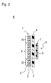
- FIG. 2 is a cross-sectional view schematically illustrating the configuration of an electrode group 4 including the negative electrode 1 shown in FIG. 1 .
- FIG. 2 is a horizontal cross-sectional view when the electrode group 4 is placed with its longitudinal direction matching the vertical direction.
- the negative electrode 1 includes a negative electrode active material layer 2 and a negative electrode current collector 3.
- the negative electrode active material layer 2 is provided on a side of a separator 8 on which a positive electrode current collector 7 of a positive electrode active material layer 6 is not provided, include a opposing portion 9 opposing the positive electrode active material layer 6 and a non-opposing portion 10 not opposing the positive electrode active material layer 6, and contains a negative electrode active material primarily containing silicon or tin.
- the negative electrode 1 is disposed as shown in FIG 2 such that the negative electrode active material layer 2 and the positive electrode active material layer 6 of a positive electrode 5 oppose each other with the separator 8 interposed therebetween.
- the negative electrode 1 and the separator 8 as well as the positive electrode 5 and the separator 8 are shown spaced apart from each other, but they may be disposed in contact with each other.
- the negative electrode active material layer 2 is formed so as to have a horizontal width larger than that of the positive electrode 5. The purpose of this is to reduce variation of the opposing area between the positive electrode active material layer 6 and the negative electrode active material layer 2 and prevent lithium from depositing on a portion other than the negative electrode active material layer 2. Accordingly, the negative electrode 1 includes the opposing portion 9 and the non-opposing portion 10 in the negative electrode active material layer 2.
- the opposing portion 9 is a portion that opposes the positive electrode active material layer 6 and takes part in the absorption and desorption of lithium.
- the width w of the opposing portion 9 is almost the same as the width of the positive electrode active material layer 6.
- the non-opposing portion 10 is a portion that hardly takes part in the absorption and desorption of lithium because it is not opposing the positive electrode active material layer 6.
- the negative electrode active material layer 2 is formed to have a width equal to that of the negative electrode current collector 3, but the negative electrode active material layer 2 may have a width smaller than that of the negative electrode current collector 3 as long as the width of the negative electrode active material layer 2 is larger than that of the positive electrode 5. Accordingly, the negative electrode current collector 3 may include, on its surface, a portion where the negative electrode active material layer 2 is not formed.
- the non-opposing portion 10 of the negative electrode active material layer 2 contains lithium produced by a thin film-forming method.
- the lithium produced by a thin film-forming method is lithium that is inert in charge and discharge reactions, that is, lithium that does not take part in charge and discharge reactions.
- the lithium produced by a thin film-forming method is not used in discharge.
- the inclusion of such lithium produced by a thin film-forming method means that lithium is included even in a discharged state.
- the term "discharged state” refers to a state in which the lithium that takes part in charge and discharge reactions (hereinafter referred to simply as "active lithium”) is not stored in the opposing portion 9 in a preset range ranging from a discharge start voltage to a discharge end voltage.
- the discharged state also encompasses a state in which only lithium that is not used in discharge is added to both the opposing portion 9 and the non-opposing portion 10.
- a specific example of the state in which the non-opposing portion 10 in a discharged state includes the lithium produced by a thin film-forming method includes, for example, a state in which only lithium is added to the opposing portion 9, and almost the same amount as that added to the opposing portion 9 or more of lithium is added to the non-opposing portion 10.
- the step becomes smaller as compared to the case in which lithium in an amount equivalent to the irreversible capacity is applied only to the opposing portion 9.
- the present invention by taking measures against irreversible capacity, only a small step or no step is created. Accordingly, even when a step is created as a result of the volume expansion of the opposing portion 9 in a charged state, the sum total of the step created after taking measures against irreversible capacity and the step created in a charged state becomes smaller as compared to that of conventional negative electrodes. As a result, distortion that occurs in the negative electrode current collector 3 in the boundary between the opposing portion 9 and the non-opposing portion 10 as well as in the vicinity thereof is mitigated.
- Mitigating the distortion of the negative electrode current collector 3 is very important.
- assembling a battery involves the processes of cutting a negative electrode 1, a positive electrode 5 and a separator 8 to their designed sizes, disposing them such that the negative electrode 1 and the positive electrode 5 oppose each other with the separator 8 interposed therebetween, and spirally winding or laminating them. If a distortion occurs in the negative electrode current collector 3 at the boundary between the opposing portion 9 and the non-opposing portion 10 during the above processes, a possibility arises that not only the negative electrode current collector 3 but also the negative electrode 1 may deform.
- the amount of distortion that occurs in the negative electrode current collector 3 at a portion adjacent to the boundary between the opposing portion 9 and the non-opposing portion 10 is reduced.
- the distortion that occurs in the negative electrode current collector 3 is successfully mitigated by adding lithium also to the non-opposing portion 10 by a thin film-forming method as described above.
- not only deformation of the negative electrode current collector 3, but also deformation of the negative electrode 1 is reduced, preventing cracking of the negative electrode active material, separation of the negative electrode active material layer 2 from the negative electrode current collector 3, and the like; thus, the cycle characteristics and the like of the battery can be improved.
- the volume after absorbing lithium to the maximum is 4.4 times the volume before absorbing lithium.
- the step created during charging also becomes relatively large.
- the amount of lithium produced by a thin film-forming method that is added to the non-opposing portion 10 can be selected as appropriate from a wide range according to various conditions, but it is preferable to select from a range ranging from an amount equivalent to the irreversible capacity or more to an amount equal to the full charge or less.
- the various conditions include, for example, the relationship between the rate of volume change and the absorbed amount of lithium of the opposing portion 9, the mechanical strength of the negative electrode current collector 3, etc.
- the amount of lithium per unit area added to both the opposing portion 9 and the non-opposing portion 10 is larger than the amount of lithium per unit area added to the opposing portion 9.
- a specific example of this configuration includes, for example, a configuration in which the amount of lithium added to the opposing portion 9 by a thin film-forming method is set to an amount equivalent to the irreversible capacity, and the amount of lithium added to the non-opposing portion 10 by a thin film-forming method is selected from a range ranging from greater than the amount equivalent to the irreversible capacity amount to less than the amount equal to the full charge.
- lithium is added to the non-opposing portion 10 by a thin film-forming method in an amount that can cause the non-opposing portion 10 to undergo a volume change half the volume change of the opposing portion 9 when expanded at the maximum.
- the amount of lithium per unit area added to the non-opposing portion 10 by a thin film-forming method is almost the same as the amount of lithium per unit area added to the opposing portion 9 by a thin film-forming method.
- a specific example of this configuration includes, for example, a configuration in which an amount of lithium equivalent to the irreversible capacity is added to the opposing portion 9 and the non-opposing portion 10 by a thin film-forming method. With this configuration, it becomes possible to cause the opposing portion 9 of the negative electrode active material layer 2 to absorb almost all lithium contained in the positive electrode active material layer 6, while mitigating the distortion that occurs in the negative electrode current collector 3, and as a result, a higher capacity can be achieved.
- Lithium is not necessarily added to the whole non-opposing portion 10. That is, as long as the effect of mitigating the distortion of the negative electrode current collector 3 can be exhibited, the non-opposing portion 10 may include a portion where lithium is not added, depending on the battery design and the manufacturing process. In addition, even when lithium is added only to the vicinity of the boundary between the non-opposing portion 10 and the opposing portion 9, a rapid volume change in the vicinity of the boundary can be reduced, so a certain level of effect of the present invention is exhibited. Of course, lithium may be added to the whole non-opposing portion 10.
- the negative electrode active material layer 2 is provided on the side of the separator 8 on which the positive electrode active material layer 6 is not provided. More specifically, the negative electrode active material layer 2 is formed on both surfaces in the thickness direction of the negative electrode current collector 3, and contains a negative electrode active material primarily containing lithium and silicon or tin. In the present embodiment, the negative electrode active material layer 2 is formed on both surfaces of the negative electrode current collector 3, but the configuration is not limited thereto, and the negative electrode active material layer 2 may be formed on only one surface of the negative electrode current collector 3.
- the negative electrode active material primarily containing silicon as long as it is capable of electrochemically reacting with lithium and, for example, silicon, a silicon compound or the like can be used.
- silicon compounds include silicon-containing alloy, silicon oxide, silicon nitride, etc.
- the negative electrode active material primarily containing tin as long as it is capable of electrochemically reacting with lithium and, for example, tin, a tin compound or the like can be used.
- examples of such a tin compound include tin-containing alloy, tin oxide, tin nitride, etc.
- Such a negative electrode active material primarily containing silicon or tin has a relatively high reactivity with lithium, and therefore a high capacity can be expected.
- the negative electrode active material primarily containing silicon or tin the above materials can be used alone or in a combination of two or more as appropriate.
- the negative electrode active material primarily containing silicon or tin is amorphous or has low crystallinity.
- low crystallinity refers to a state in which the crystal grains have a grain size of 50 nm or less.
- the grain size of crystal grains is calculated according to the Scherrer equation from the half-value width of a peak having the highest intensity in a diffraction image obtained by X-ray diffractometry.
- the thickness of the negative electrode active material layer 2 can be selected as appropriate according to the performance set for the battery to be produced, but the thickness is preferably 3 to 40 ⁇ m.
- the thickness is preferably 3 to 40 ⁇ m.
- the proportion of the negative electrode active material in the whole battery becomes small, and the energy density of the battery may decrease.
- the negative electrode active material layer 2 has a thickness exceeding 40 ⁇ m, the stress at the interface between the negative electrode current collector 3 and the negative electrode active material layer 2 increases, making it more likely to cause deformation in the negative electrode current collector 3, and the like, even when the configuration of the present invention is applied.
- the negative electrode current collector 3 is provided on the side of a negative electrode active material layer 2 on which the separator 8 is not provided.
- any negative electrode current collector widely used in the field of lithium ion secondary batteries can be used and, for example, a porous or poreless conductive substrate made of a metal material such as copper, nickel or stainless steel can be used.
- porous conductive substrates include mesh, net, punched sheet, lath structures, porous sheet, foam, articles made of fibers (non-woven fabric, etc.), etc.
- poreless conductive substrates include foil, sheet, film, etc.
- the thickness of the conductive substrate is preferably 10 to 50 ⁇ m, and more preferably 15 to 40 ⁇ m considering mechanical strength, volume efficiency as a battery, the ease of handling, and so on. It is also possible to provide a plurality of protrusions on the surface of the negative electrode current collector 3. With this configuration, the strength of adhesion between the negative electrode current collector 3 and the negative electrode active material layer 2 can be improved.
- the substrate portion and the protrusion portion may be made of the same material or may be made of different materials.
- the protrusions can be formed by, for example, plating, etching or the like.
- the negative electrode 1 can be manufactured by, for example, a manufacturing method involving a thin film-forming step and a lithium adding step.
- a thin film containing a negative electrode active material primarily containing silicon or tin is formed on the surface of the negative electrode current collector 3 by a thin film-forming method.
- the thin film-forming method is performed by, for example, a vacuum process.
- the vacuum process can be, for example, a generally used vapor deposition thin film-forming method such as a vapor deposition method, a sputtering method and a CVD method (chemical vapor deposition method). It is preferable to use a vapor deposition method in particular.
- the thin film can be formed on the surface of the negative electrode current collector 3 by, for example, using a film-forming apparatus 11 shown in FIG 3 .
- FIG 3 is a vertical cross-section view schematically illustrating the configuration of a relevant part of the film-forming apparatus 11.
- the film-forming apparatus 11 includes a vacuum chamber 12, a feeding roller 13, transfer rollers 14, a first can roller 15, a second can roller 16, a winding roller 17, an active material adding means 18, shielding plates 19, raw material gas-introducing pipes 20 and air exhaust means 21.
- the film-forming apparatus 11 is an apparatus for producing a laminate in which thin films are formed on both surfaces in the thickness direction of the negative electrode current collector 3.
- the vacuum chamber 12 is a pressure-resistant vessel member having an internal space, and includes, in the internal space, the feeding roller 13, the transfer rollers 14, the first can roller 15, the second can roller 16, the winding roller 17, the active material adding means 18, the shielding plates 19 and the raw material gas-introducing pipes 20.
- the feeding roller 13 is a roller member provided above in a direction vertical to the first can roller 15 so as to be capable of rotating about the axis.
- a long strip-shaped negative electrode current collector 3 is spirally wound around the surface of the feeding roller 13, and the feeding roller 13 supplies the negative electrode current collector 3 to the transfer roller 14 located closest to the feeding roller 13.
- the transfer rollers 14 are roller members provided so as to be capable of rotating about the axis.
- the transfer rollers 14 guide the negative electrode current collector 3 supplied from the feeding roller 13 to the first can roller 15, the second can roller 16, and finally to the winding roller 17.
- the first can roller 15 and the second can roller 16 are roller members provided so as to be capable of rotating about their respective axes, and include cooling means (not shown) in the inside thereof.
- the cooling means for example, a cooling apparatus that performs cooling by circulating cooling water, or the like, can be used.
- a negative electrode active material layer 2 is formed on a surface of the negative electrode current collector 3 while the negative electrode current collector 3 moves along the circumference of the first can roller 15 and the second can roller 16.
- first can roller 15 and the second can roller 16 are provided such that their axes are located in parallel to each other at the same position in the vertical direction, and that their circumferences are spaced apart from each other with a gap therebetween.
- the winding roller 17 is a roller member provided in a direction vertical to the second can roller 16 so as to be capable of being driven to rotate by a driving means (not shown), and winds the negative electrode current collector 3 in which thin films have been formed on both surfaces for storage.
- the active material adding means 18 are container members that are provided verdically below the lowermost portion in the direction vertical to the first can roller 15 and the second can roller 16, and whose upper portion in the vertical direction is open. Inside the active material adding means 18, an alloy-based negative electrode active material is placed. A heating means (not shown) is provided in the vicinity of the active material adding means 18, and the alloy-based negative electrode active material within the active material adding means 18 is heated and evaporated by this heating means.
- the vapor of the alloy-based negative electrode active material travels upward in the vertical direction, passes through openings 22 and 23, which will be described later, and arrives at the lowermost portion in the direction vertical to the first can roller 15 and the second can roller 16, where it attaches to the surface of the negative electrode current collector 3 and, thus, a thin film (negative electrode active material layer 2) made of a negative electrode active material primarily containing silicon or tin is formed.
- the active material adding means 18 for example, crucibles can be used.
- the heating means for example, electron beam irradiation apparatuses or the like can be used.
- the active material adding means 18 are disposed to be aligned almost linearly with the first can roller 15 and the second can roller 16 in the vertical direction, but the configuration is not limited thereto, and it is also possible to dispose the active material adding means 18 obliquely below in the direction vertical to the first can roller 15 and the second can roller 16. With this configuration, the active material is deposited obliquely, so a thin film having pores inside is formed.
- a plurality of shielding plates 19 are provided spaced apart from each other with a gap therebetween at the same height in the vertical direction.
- the gaps formed in the horizontal direction between shielding plates 19 are openings 22 and 23.
- the shielding plates 19 are provided to cause the active material vapor released from the active material adding means 18 to come into contact with only the portions of the negative electrode current collector 3 corresponding to the openings 22 and 23.
- the raw material gas introducing pipes 20 are pipe-like members that are each disposed with one end vertically above the active material adding means 18 and the other end connected to a raw material gas supply means (not shown) provided outside the vacuum chamber 12, and that supply oxygen, nitrogen or the like to the active material vapor. With this, a thin film primarily containing an oxide, nitride or oxynitride of the alloy-based negative electrode active material is formed on the negative electrode current collector 3 surface.
- Examples of raw material supply means include a compressed gas cylinder, a gas generation apparatus, etc.
- the air exhaust means 21 provided outside the vacuum chamber 12 brings the inside of the vacuum chamber 12 into a reduced pressure state suitable for making thin films. As the air exhaust means 21, for example, a pressure reducing pump or the like can be used.
- the negative electrode current collector 3 sent from the feeding roller 13 moves along the circumference of the first can roller 15 via the transfer roller 14, receives a supply of active material vapor and optionally oxygen, nitrogen or the like at the opening 22, and thereby a thin film (negative electrode active material layer 2) containing a negative electrode active material primarily containing silicon or tin is formed on one surface of the negative electrode current collector 3.
- the negative electrode current collector 3 is then reversed by other transfer rollers 14 to move along the circumference of the second can roller 16.
- the negative electrode current collector 3 receives a supply of active material vapor and optionally oxygen, nitrogen or the like at the opening 23 and, thereby, a thin film containing a negative electrode active material primarily containing silicon or tin is formed on the other surface of the negative electrode current collector 3.
- the negative electrode current collector 3 having thin films (negative electrode active material layers 2) formed on both surfaces thereof passes through another transfer roller 14, and is wound by the winding roller 17. In this manner, a negative electrode current collector 3 having negative electrode active material layers 2 formed on both surfaces thereof is obtained, and the thin film-forming step ends.
- a thin lithium film is formed using a thin film-forming method on the negative electrode active material layer 2 surface of the negative electrode current collector 3 obtained in the thin film-forming step so as to produce a negative electrode 1 of the present invention.
- a thin lithium film is formed not only on the opposing portion 9 but also on the non-opposing portion 10 so as to add lithium.
- the thin lithium film-forming method any known method can be used and, for example, a direct addition method can be used.
- the direct addition method lithium is added by forming a thin lithium film on the negative electrode active material layer 2 surface using an apparatus capable of forming thin lithium films by a vacuum process. Specific examples of vacuum processes include the above-mentioned vapor deposition thin film-forming methods. Among them, the vapor deposition method is preferable in particular.
- an appropriate thin lithium film-forming method is selected according to the amount of lithium added to the opposing portion 9 and the non-opposing portion 10 (hereinafter referred to simply as "lithium addition amount').
- lithium addition amount' the amount of lithium added to the opposing portion 9 and the non-opposing portion 10.
- the lithium addition amount for the non-opposing portion 10 is larger than that for the opposing portion 9 as well, it is preferable to employ the direct addition method.
- the direct addition method because lithium is added to the negative electrode active material layer 2 by forming a thin lithium film, it is easy to adjust the lithium addition amount. For example, when continuously processing a long negative electrode current collector 3, by providing a mask to limit the application of a thin lithium film in which the dimensions of the openings for a non-opposing portion 10 are made larger than that for the opposing portion 9, lithium can be added to the opposing portion 9 and the non-opposing portion 10 at the desired ratio.
- a thin lithium film is formed on the negative electrode current collector 3 having negative electrode active material layers 2 obtained in the thin film-forming step, using a metal mask positioned at the thin film-forming position by a winding type continuous film-forming method.
- the metal mask has openings for supplying lithium vapor to the negative electrode active material layer 2 of the negative electrode current collector 3.
- the openings of the metal mask are provided extending in a direction orthogonal to the longitudinal direction of the negative electrode current collector 3 (hereinafter referred to as "width direction").
- the openings of the metal mask are provided so as to be, for example, capable of being adjusted in the longitudinal direction of the negative electrode current collector. At this time, for example, by adjusting the opening length of the metal mask, lithium can be added to the opposing portion 9 and the non-opposing portion 10 of the negative electrode active material layer 2 in respective desired amounts.
- the opening length of the openings of the metal mask is increased by approximately several millimeters relative to that for the portion corresponding to the center portion in the width direction of the negative electrode current collector 3.
- the lithium amount added to both end portions may be increased stepwise from the center portion, or may be continuously increased gradually. Such adjustment can be performed by adjusting the opening shape and opening length of the metal mask.
- the lithium addition amount of the non-opposing portion 10 is preferably increased relative to the lithium addition amount of the opposing portion 9 can be determined by actually producing negative electrodes with different lithium addition amounts and selecting an appropriate amount according to the deformation of the current collector after lithium is added and the deformation when charge and discharge are performed.
- the effect of the present invention is exhibited not only when the lithium addition amount for opposing portion 9 exactly matches the irreversible capacity. That is, the effect of the present invention is obtained by mitigating an extreme difference in deformation that occurs between the opposing portion 9 and the non-opposing portion 10 between when lithium is applied and when charge and discharge are performed. Accordingly, needless to say, the effect of the present invention is exhibited even when the lithium addition amount slightly fluctuates relative to the amount equivalent to the irreversible capacity due to an error or human operation.
- the negative electrode capacity is much larger than the positive electrode capacity
- by intentionally adding lithium in an amount slightly larger than the irreversible capacity it is possible to prevent battery capacity degradation due to variation in the negative electrode plate.
- the positive electrode capacity is much larger than the negative electrode capacity
- a slightly smaller amount of lithium than the irreversible capacity can be applied intentionally.
- the end portions in the width direction include a portion on which no thin film is formed, that portion is cut, and the current collector is cut to a prescribed length, and, thereby, a negative electrode 1 of the present invention can be obtained.
- the negative electrode 1 of the present invention is applicable to various types of lithium secondary batteries. Although there is no particular limitation on the battery shape and the sealing form, it is particularly effective when used in a secondary battery with a spirally wound design, a stacked design or the like.
- FIG 4 is a vertical cross-sectional view schematically illustrating the configuration of a lithium ion secondary battery 30 according to an embodiment of the present invention.
- a feature of the lithium ion secondary battery 30 is the inclusion of a negative electrode 1 of the present invention, and other constituents are the same as those of a conventional lithium ion secondary battery.
- the lithium ion secondary battery 30 is a spirally wound secondary battery including a spirally wound electrode group 31, a positive electrode lead 34, a negative electrode lead 35, an upper insulating ring 36, a lower insulating ring 37, a battery can 38, a sealing plate 39, and an insulating gasket 40.
- the electrode group 31 includes a negative electrode 1, a positive electrode 32 and a separator 33, and is housed in the battery can 38.
- the negative electrode 1, the positive electrode 32 and the separator 33 are all strip-shaped, and by spirally winding the negative electrode 1 and the positive electrode 32 with the separator 33 interposed therebetween, the electrode group 31 is obtained.
- the negative electrode 1 is the above-described negative electrode 1 for a lithium ion secondary battery of the present invention.
- the non-opposing portion may be in both end portions in the longitudinal direction of the negative electrode 1, or may be located in a portion other than the end portions.
- the positive electrode 32 includes a positive electrode current collector (not shown) and a positive electrode active material layer.
- the positive electrode active material layer is provided in contact with the positive electrode current collector, and the separator 33 is provided on the side of the positive electrode active material layer on which the positive electrode current collector is not provided. It is preferable that the positive electrode 32 is formed such that the width in the longitudinal direction is slightly smaller than the width in the longitudinal direction of the negative electrode 1. The purpose of this is to, as already stated above, prevent lithium from depositing on the current collector of the negative electrode 1 during charge, and the like.
- the current collector can be any current collector widely used in the pertinent art.
- a porous or poreless conductive substrate can be used.
- porous conductive substrates include mesh, net, punched sheet, lath structures, porous sheet, foam, articles made of fibers (non-woven fabric, etc.), and the like.
- poreless conductive substrates include foil, sheet, film, and the like.
- materials for conductive substrates include metal materials such as stainless steel, titanium, aluminum and aluminum alloy.
- the thickness of the conductive substrate is, but is not limited to, for example, approximately 1 to 50 ⁇ m.
- the positive electrode active material layer is provided on only one surface or both surfaces in the thickness direction of the positive electrode current collector, and contains a positive electrode active material.
- the positive electrode material mixture layer may further contain, in addition to the positive electrode active material, a conductive material, a binder, and the like.
- the positive electrode active material commonly used positive electrode active materials capable of absorbing and desorbing lithium ions can be used. Among them, it is preferable to use a lithium-containing composite oxide.
- the lithium-containing composite oxide known lithium-containing composite oxides can be used. Examples include lithium nickel composite oxide such as LiNiO 2 , lithium cobalt composite oxide such as LiCoO 2 , and lithium manganese composite oxide such as spinel structured LiMn 2 O 4 . It is also possible to use a lithium-containing composite oxide in which some of the transition metals are substituted by another element, as the positive electrode active material. For example, it is also possible to use a composite oxide obtained by substituting some of the Ni elements of LiNiO 2 with Co or another element (Al, Mn, Ti, etc.).
- any conductive material widely used in the pertinent art can be used. Examples include: graphites such as natural graphite and artificial graphite; carbon blacks such as acetylene black, ketjen black, channel black, furnace black, lamp black and thermal black; conductive fibers such as carbon fiber and metal fiber; metal powders such as a carbon fluoride powder and an aluminum powder; conductive whiskers such as zinc oxide and potassium titanate; conductive metal oxides such as titanium oxide; and organic conductive materials such as phenylene derivatives. As the conductive material, they may be used alone or in a combination of two or more as appropriate.
- the binder can be any binder widely used in the pertinent art.
- binder examples include polyvinylidene fluoride (PVDF), polytetrafluoroethylene, polyethylene, polypropylene, aramid resin, polyamide, polyimide, polyamide imide, polyacrylonitrile, polyacrylic add, polymethyl acrylate, polyethyl acrylate, polyhexyl acrylate, polymethacrylic add, polymethyl methacrylate, polyethyl methacrylate, polyhexyl methacrylate, polyvinyl acetate, polyvinyl pyrrolidone, polyether, polyether sulfone, hexafluoropolypropylene, styrene butadiene rubber, carboxymethyl cellulose, etc.
- PVDF polyvinylidene fluoride
- PVDF polytetrafluoroethylene
- polyethylene polyethylene
- polypropylene aramid resin
- polyamide polyimide
- binder it is also possible to use a copolymer containing two or more of the following monomer compounds.
- monomer compounds include tetrafluoroethylene, hexafluoropropylene, perfluoroalkyl vinyl ether, vinylidene fluoride, chlorotrifluoroethylene, ethylene, propylene, pentafluoropropylene, fluoromethyl vinyl ether, acrylic acid, hexadiene, etc.
- binder they may be used alone or in a combination of two or more as appropriate.
- the positive electrode active material layer can be formed by, for example, applying a positive electrode material mixture slurry onto the surface of a positive electrode core member, drying and drawing it.
- the positive electrode material mixture slurry can be prepared by dissolving or dispersing a positive electrode active material and optionally a conductive material, a binder and the like in an organic solvent.
- the organic solvent for example, dimethylformamide, dimethylacetamide, methylformamide, N-methyl-2-pyrrolidone (NMP), dimethylamine, acetone, cyclohexanone or the like can be used.
- NMP N-methyl-2-pyrrolidone
- dimethylamine acetone
- cyclohexanone cyclohexanone
- There is no particular limitation on the thickness of the positive electrode active material layer but it is preferable that, when the positive electrode active material layer is provided on both sides of a current collector, for example, the total thickness of the positive electrode active material layers is approximately 50 to 100 ⁇ m.
- the separator 33 is provided on the side of the positive electrode active material layer on which the positive electrode current collector is not provided. More specifically, the separator 33 is provided interposed between the positive electrode 32 and the negative electrode 1.
- the width in the longitudinal direction of the separator 33 is configured to be longer than the widths in the longitudinal direction of the positive electrode 32 and the negative electrode 1.
- a separator it is possible to use a separator widely used in the pertinent art and, for example, a porous sheet made of a synthetic resin material can be used.
- the synthetic resin material but it is preferable to use a polyolefin such as polyethylene or polypropylene.
- Specific examples of the porous sheet include a porous film, woven fabric, non-woven fabric and the like.
- the separator thickness and it is possible to select from a range ranging from approximately 10 to 300 ⁇ m as appropriate, according to the form, application and the like of the lithium ion secondary battery.
- an electrolyte (not shown) is impregnated or carried.
- the electrolyte is preferably a non-aqueous electrolyte.
- a non-aqueous electrolyte for example, a liquid non-aqueous electrolyte, gel non-aqueous electrolyte, solid electrolyte (e.g., polymer solid electrolyte) or the like can be used.
- the liquid non-aqueous electrolyte contains a solute (supporting salt) and a non-aqueous solvent, and optionally contains various additives.
- the solute ordinarily dissolves in the non-aqueous solvent.
- the liquid non-aqueous electrolyte is, for example, impregnated into the separator.
- the solute can be any solute widely used in the pertinent art.
- Usable examples include LiClO 4 , LiBF 4 , LiPF 6 , LiAlCl 4 , LiSbF 6 , LiSCN, LiCF 3 SO 3 , LiCF 3 CO 2 , LiAsF 6 , LiB 10 Cl 10 , lithium lower aliphatic carboxylates, LiCl, LiBr, Lil, chloroboran lithium, borate, imide, etc.
- borates include lithium bis(1,2-benzenediolate(2-)-O,O')borate, lithium bis(2,3-naphthalenediolate(2-)-O,O')borate, lithium bis(2,2'-biphenyldiolate(2-)-O,O')borate, lithium bis(5-fluoro-2-olate-1-benzene sulfonate-O,O')borate, etc.
- imides examples include lithium bis(trifluoromethanesuffonyl)imide ((CF 3 SO 2 ) 2 NLi), lithium (trifluoromethanesulfonyl)(nonafluorobutanesulfonyl)imide ((CF 3 SO 2 )(C 4 F 9 SO 2 )NLi), lithium bis(pentafluoroethane sulfonyl)imide ((C 2 F 5 SO 2 ) 2 NLi), etc.
- the solute may be used alone or in a combination of two or more as appropriate. It is desirable that the amount of solute dissolved in a non-aqueous solvent is within a range ranging from 0.5 to 2 mol/L.
- the non-aqueous solvent can be any non-aqueous solvent widely used in the pertinent art.
- examples include cydic carbonic add esters, chain carbonic add esters, cydic carboxylic add esters, etc.
- examples of cydic carbonic add esters include propylene carbonate (PC), ethylene carbonate (EC), butylene carbonate, etc.
- Examples of chain carbonic add esters include diethyl carbonate (DEC), ethyl methyl carbonate (EMC), dimethyl carbonate (DMC), methyl propionate, etc.
- Examples of cydic carboxylic add esters include ⁇ -butyrolactone (GBL), ⁇ -valerolactone (GVL), etc. It is also possible to use non-aqueous solvents having an oxidation/reduction resistant potential at a level of around 4 V. As the non-aqueous solvent, they may be used alone or in a combination of two or more as appropriate.
- additives include a material that can improve charge/discharge efficiency, a material that can make the battery inactive, etc.
- the material that can improve charge/discharge efficiency for example, decomposes on the negative electrode and forms a coating having a high lithium ion conductivity to improve charge/discharge efficiency.
- Such a material examples include vinylene carbonate (VC), 4-methylvinylene carbonate, 4,5-dimethylvinylene carbonate, 4-ethylvinylene carbonate, 4,5-diethyl vinylene carbonate, 4-propylvinylene carbonate, 4,5-dipropylvinylene carbonate, 4-phenyl vinylene carbonate, 4,5-diphenyl vinylene carbonate, vinylethylene carbonate (VEC), divinyl ethylene carbonate, etc. They may be used alone or in a combination of two or more. Among them, it is preferable to use at least one selected from vinylene carbonate, vinylethylene carbonate and divinyl ethylene carbonate. In the above compounds, some of the hydrogen atoms may be substituted by fluorine atoms.
- the solid electrolyte contains a solute (supporting salt) and a polymer material.
- the solute can be any of those listed above.
- the polymer material for example, polyethylene oxide (PEO), polypropylene oxide (PPO), a copolymer of ethylene oxide and propylene oxide, or the like can be used.
- the positive electrode lead 34 is connected to the positive electrode 31, and the other end is connected to the sealing plate 39.
- the positive electrode lead 34 is made of, for example, aluminum.
- One end of the negative electrode lead 35 is connected to the negative electrode 1, and the other end is connected to the bottom of the battery can 38.
- the negative electrode lead 35 is made of, for example, copper, nickel or the like.
- the electrode group 32 is housed inside the battery can 38.
- the upper insulating ring 36 is mounted on one end in the longitudinal direction of the electrode group 31.
- the lower insulating ring 37 is mounted on the other end in the longitudinal direction of the electrode group 32, and insulates the electrode group 31 and the bottom of the battery can 38 from each other.
- the sealing plate 39 is provided such that it doses the upper opening of the battery can 38 so as to seal the battery can 38.
- the insulating gasket 40 is provided in the periphery portion of the sealing plate 39 so as to help the sealing plate 39 to seal the battery can 38.
- the insulating gasket 40 is made of, for example, polypropylene or the like.
- FIG 5 is a vertical cross-sectional view schematically illustrating the configuration of a lithium ion secondary battery 41 according to another embodiment of the present invention.
- the lithium ion secondary battery 41 is analogous to the lithium ion secondary battery 30, the same reference numerals are assigned to the corresponding parts, and descriptions thereof are omitted here.
- a feature of the lithium ion secondary battery 41 is that it is a stacked battery in the form of a sheet that includes an electrode group 42 that includes a negative electrode 1. The effect of the present invention is obtained even in stacked batteries.
- the lithium ion secondary battery 41 includes an electrode group 42, an external positive electrode 43, an external negative electrode 44, and an insulator 45.
- the electrode group 42 is a laminated electrode group in which a plurality of unit electrode groups 31 a and a plurality of separators 33 are alternately laminated.
- the unit electrode groups 31 a are each an electrode group in which one negative electrode 1 and one positive electrode 32 are laminated with one separator 33 interposed therebetween.
- the negative electrode 1 has a negative electrode active material layer including a opposing portion opposing the positive electrode active material layer of the positive electrode 32 and a non-opposing portion not opposing the positive electrode active material layer of the positive electrode 32.
- the opposing portion and the non-opposing portion contain a prescribed amount of lithium as already described above.
- the external positive electrode 43 is a metallic member, and is electrically connected to the positive electrode 32 of the electrode group 42.
- the external negative electrode 44 also is a metallic member, and is electrically connected to the negative electrode 1 of the electrode group 42.
- the insulator 45 is an insulating member made of a synthetic resin or the like, and is disposed on both end portions in a direction orthogonal to the thickness direction of the electrode group 42.
- the insulator 45 on the external positive electrode 43 side end portion is disposed between the negative electrode 1 and the external positive electrode 43, and insulates the negative electrode 1 and the external positive electrode 43 from each other.
- the insulator 45 on the external negative electrode 44 side end portion is disposed between the positive electrode 32 and the external negative electrode 44, and insulates the positive electrode 32 and the external negative electrode 44 from each other.
- Example 1 A negative electrode for a lithium ion secondary battery and a lithium ion secondary battery according to the present invention were produced.
- a roll of surface-roughened copper foil (negative electrode current collector 3, thickness: 35 ⁇ m, width: 80 mm, available from Furukawa Circuit Foil Co., Ltd.) was loaded into the winding roller 13 of the film-forming apparatus 11 shown in FIG. 3 .
- a 270-degree deflection electron beam evaporation source (available from JEOL Ltd.) was used as an active material adding means 18. Silicon as an active material was irradiated with an electron beam with an accelerating voltage of -10 kV and an emission current of 500 mA, and the film forming rate was set to 120 nm/sec.
- the first can roller 15 and the second can roller 16 were cooled with cooling water at 10°C by a cooling water circulation cooling apparatus.
- a metal mask having an opening length of 20 cm was provided in the vicinity of the underside in the direction vertical to the first can roller 15 and the second can roller 16, and the width of the formed film (the width in a direction orthogonal to the longitudinal direction of the surface-roughened copper foil) was set to 60 mm.
- the vacuum chamber 12 was evacuated to 0.002 Pa, and then the degree of the vacuum in the vacuum chamber 12 was adjusted to 0.003 Pa.
- the surface-roughened copper foil was fed to the first can roller 15 and the second can roller 16 at a feed rate of 0.36 m/min, and a 4 ⁇ m thick, thin silicon film was formed on each surface of the surface-roughened copper foil at the regions constituting the openings 22 and 23. No raw material gas was introduced.
- a surface-roughened copper foil having a 4 ⁇ m thick, thin silicon film formed on only one surface was produced by closing the opening portion of the metal mask corresponding to the second can roller.
- the above-obtained surface-roughened copper foil having a thin silicon film with a thickness of 4 ⁇ m and a width of 60 mm formed on only one surface was cut into a 12 mm diameter piece, and a coin battery was assembled using a lithium counter electrode.
- This coin battery was subjected to a charge/discharge test with constant current charge/discharge at 0.2 C (1 C is one hour rate current), and the charge capacity and the discharge capacity in the initial charge/discharge cycle were measured.
- the charge capacity was equivalent to a lithium thickness of 20 ⁇ m. From the results obtained from measurement, the irreversible capacity was calculated using the following equation, and found to be about 6%, from which it was found that it was necessary to add lithium in an amount equivalent to a lithium thickness of 1.2 ⁇ m.
- a roll of the surface-roughened copper foil having 4 ⁇ m thick, thin silicon films formed on both surfaces was loaded onto the winding roller 13 of the film-forming apparatus 11 shown in FIG. 3 .
- a resistance heating evaporation source was used as an active material adding means 18. Lithium as a vapor source was heated by a heater, and the application rate of lithium vapor was set to 80 nm/sec.
- the first can roller 15 and the second can roller 16 were cooled with cooling water at 10°C by a cooling water circulation cooling apparatus.
- a metal mask having an opening length of 20 cm was provided in the vicinity of the underside in the direction vertical to the first can roller 15 and the second can roller 16, and the width of the formed film was set to 60 mm.
- the vacuum chamber 12 was evacuated to 0.001 Pa, and then the degree of vacuum in the vacuum chamber 12 was adjusted to 0.002 Pa.
- the surface-roughened copper foil having 4 ⁇ m thick, thin silicon films formed on both surfaces was fed to the first can roller 15 and the second can roller 16 at a feed rate of 0.8 m/min, and a thin lithium film having a thickness of 1.2 ⁇ m and a width of 60 mm was formed on the surface of respective thin silicon films having a width of 60 mm formed on both surfaces of the surface-roughened copper foil at the regions constituting the openings 22 and 23, without introducing a raw material gas.
- the copper foil was cut at both ends in the width direction in which no thin silicon film was formed, and then cut into a 900 mm long piece.
- a negative electrode of the present invention was produced.
- a mixture of Li 2 CO 3 and CoCO 3 mixed at a prescribed molar ratio was heated at 950°C to prepare LiCoO 2 as an active material, and the obtained active material was sized to a particle size of 45 ⁇ m or less to obtain a positive electrode active material.
- the positive electrode active material in an amount of 100 parts by weight was sufficiently mixed with 5 parts by weight of acetylene black (conductive material), 4 parts by weight of polyvinylidene fluoride (binder) and an appropriate amount of N-methyl-2-pyrrolidone (dispersing medium) to prepare a positive electrode material mixture paste.
- the positive electrode material mixture paste was applied to both surfaces of a 15 ⁇ m thick aluminum foil (current collector, available from Showa Denko K.K), dried and rolled and, thereby, 35 ⁇ m thick positive electrode active material layers were formed on both surfaces of the current collector.
- the current collector was cut to have a width of 56 mm and a length of 900 mm and, thereby, a positive electrode was produced.
- An end of a positive electrode lead made of aluminum was welded to the positive electrode current collector.
- An end of a negative electrode lead made of nickel was welded to the negative electrode current collector.
- the positive electrode, a microporous film (separator) made of polyethylene resin having a width of 62 mm, a length of 910 mm and a thickness of 20 ⁇ m, and the negative electrode were laminated in this order and spirally wound and, thereby, an electrode group was produced.
- This electrode group was placed in a dry atmosphere with a dew point of -60°C, and vacuum-dried at 60°C for 10 hours to remove moisture from the electrode group. After that, insulating rings were attached to both ends in the longitudinal direction of the electrode group, and then the electrode group was housed in a battery can.
- a non-aqueous electrolyte was injected into the battery can to impregnate the electrode group with the electrolyte.
- an electrolyte obtained by dissolving lithium hexafluorophosphate at a concentration of 1 mol/L in a solvent mixture of ethylene carbonate and diethyl carbonate at a volume ratio of 1:1 was used as the non-aqueous electrolyte.
- the other end of the positive electrode lead was welded to the undersurface of the positive electrode terminal at the center of the insulating sealing plate.
- the other end of the negative electrode lead was welded to the inner bottom surface of the battery can.
- the opening of the battery can was closed with a sealing plate and, thereby, a cylindrical lithium ion secondary battery of the present invention was produced.
- a cylindrical lithium ion secondary battery of the present invention was produced in the same manner as in Example 1, except that a negative electrode of the present invention obtained in the following manner was used.
- a roll of surface-roughened copper foil (negative electrode current collector 3, thickness: 12 ⁇ m, width: 80 mm, available from Furukawa Circuit Foil Co., Ltd.) was loaded onto the winding roller 13 of the film-forming apparatus 11 shown in FIG. 3 .
- a 270-degree deflection electron beam evaporation source (available from JEOL Ltd.) was used as an active material adding means 18. Silicon as an active material was irradiated with an electron beam with an accelerating voltage of -10 kV and an emission current of 450 mA, and the film forming rate was set to 100 nm/sec.
- the first can roller 15 and the second can roller 16 were cooled with cooling water at 10°C by a cooling water circulation cooling apparatus.
- a metal mask having an opening length of 20 cm was provided in the vicinity of the underside in the direction vertical to the first can roller 15 and the second can roller 16, and the width of the formed film was set to 60 mm.
- the vacuum chamber 12 was evacuated to 0.002 Pa, and then the degree of vacuum in the vacuum chamber 12 was adjusted to 0.04 Pa.
- the surface-roughened copper foil was fed to the first can roller 15 and the second can roller 16 at a feed rate of 0.1 m/min while introducing oxygen gas at 30 sccm at the regions constituting the openings 22 and 23, and, thereby, 12 ⁇ m thick, thin silicon oxide films were formed on both surfaces of the surface-roughened copper foil.
- the above-obtained surface-roughened copper foil having thin silicon oxide films with a width of 60 mm and a thickness of 12 ⁇ m formed on both surfaces was cut to prescribed dimensions, and a coin battery was assembled using a lithium counter electrode.
- This coin battery was subjected to a charge/discharge test with constant current charge/discharge at 0.2 C (1 C is one hour rate current), and the charge capacity and the discharge capacity in the initial charge/discharge cycle were measured.
- the charge capacity was equivalent to a lithium thickness of 20 ⁇ m. From the results obtained from measurement, the irreversible capacity was calculated using the following equation, and found to be about 40%, from which it was found that it was necessary to add lithium in an amount equivalent to a lithium thickness of 8 ⁇ m.
- a thin lithium film having a thickness of 8 ⁇ m and a width of 60 mm was formed on the surface of the thin silicon oxide film having a width of 60 mm formed on each surface of the surface-roughened copper foil in the same manner as in Example 1, except that the surface-roughened copper foil having 12 ⁇ m thick, thin silicon oxide films formed on both surfaces was fed at a feed rate of 0.12 m/min instead of 0.8 m/min. After that, the copper foil was cut at both ends in the width direction in which no thin silicon film was formed, and then cut into a 900 mm long piece. Thus, a negative electrode of the present invention was produced.
- a 4 ⁇ m thick, thin silicon film was formed on each surface of a surface-roughened copper foil (current collector, thickness: 35 ⁇ m, width: 80 mm, available from Furukawa Circuit Foil Co., Ltd.) in the same manner as in Example 1.
- Lithium was added to the thin silicon films in an amount equivalent to the irreversible capacity.
- the addition of lithium was performed in the same manner as in Example 1, except that the width of the formed thin lithium film was changed from 60 mm to 50 mm.
- a thin lithium film was formed such that 25 mm wide portions extended from the center line in the width direction of the surface-roughened copper foil toward the end portions in the width direction.
- the width of the formed film was changed by adjusting the opening width of the metal mask.
- the copper foil was cut at both ends in the width direction in which no thin silicon film was formed, and then cut into a 900 mm long piece.
- a negative electrode was produced.
- a cylindrical lithium ion secondary battery was produced in the same manner as in Example 1, except that the above negative electrode was used.
- a 12 ⁇ m thick, thin silicon oxide film was formed on each surface of a surface-roughened copper foil (current collector, thickness: 12 ⁇ m, width: 80 mm, available from Furukawa Circuit Foil Co., Ltd.) in the same manner as in Example 2.
- Lithium was added to the thin silicon films in an amount equivalent to the irreversible capacity.
- the addition of lithium was performed in the same manner as in Example 2, except that the width of the formed thin lithium film was changed from 60 mm to 50 mm.
- a thin lithium film was formed such that 25 mm wide portions extended from the center line in the width direction of the surface-roughened copper foil toward the end portions in the width direction.
- the width of the formed film was changed by adjusting the opening width of the metal mask.
- the copper foil was cut at both ends in the width direction in which no thin silicon film was formed, and then cut into a 900 mm long piece.
- a negative electrode was produced.
- a cylindrical lithium ion secondary battery was produced in the same manner as in Example 1, except that the above negative electrode was used.
- the cylindrical lithium ion secondary batteries of Examples 1 and 2 and Comparative Examples 1 and 2 were subjected to a charge/discharge cycle test.
- As the charge/discharge cycle test each battery was cycled 200 times in a constant temperature chamber set at 20°C, with one cycle comprised of the following constant current charge, constant voltage charge and discharge.
- Constant current charge Charge was performed at a charge current of 1 C (1 C is one hour rate current) until the battery voltage reached 4.05 V
- the battery was disassembled to check for deformation in the periphery of the end portions in the width direction of the negative electrode.
- the ratio of discharge capacity at the 200th cycle to discharge capacity at the second cycle was determined as a percentage, which was defined as the capacity retention ratio (%).
- the battery discharged state
- the battery was disassembled to analyze the amount of lithium contained in the non-opposing portion not opposing the positive electrode disposed on both end portions in the width direction of the negative electrode by ICP emission spectroscopy.
- analysis was performed on the outermost 4 mm portion from each end of the 5 mm non-opposing portions not opposing the positive electrode that were formed on both ends in the width direction of the negative electrode.
- the amount of lithium contained in that region was almost the same as before charge/discharge.
- Example 1 and Comparative Example 1 the amount of lithium in the opposing portion was equivalent to a lithium film thickness of 1.2 ⁇ m
- Example 2 and Comparative Example 2 the amount of lithium in the opposing portion was equivalent to a lithium film thickness of 8 ⁇ m.
- the negative electrode used in the present invention employs a negative electrode active material primarily containing silicon or tin, and is intended to reduce not only the deformation of the current collector but also the deformation of the electrode itself that occur due to charge and discharge. Accordingly, battery reliability can be improved by using the negative electrode. Furthermore, the lithium secondary battery of the present invention that includes this negative electrode has a high capacity, and the degradation of battery characteristics, such as cycle characteristics, accompanied by the deformation of the negative electrode current collector or the negative electrode is very small. Accordingly, the battery of the present invention is suitable for use as a power source for various electronic and electrical devices, and is useful as a power source for portable electronic devices in particular.
Landscapes
- Chemical & Material Sciences (AREA)
- Engineering & Computer Science (AREA)
- Chemical Kinetics & Catalysis (AREA)
- Electrochemistry (AREA)
- General Chemical & Material Sciences (AREA)
- Materials Engineering (AREA)
- Manufacturing & Machinery (AREA)
- Inorganic Chemistry (AREA)
- Battery Electrode And Active Subsutance (AREA)
- Secondary Cells (AREA)
Applications Claiming Priority (2)
| Application Number | Priority Date | Filing Date | Title |
|---|---|---|---|
| JP2007188176 | 2007-07-19 | ||
| PCT/JP2008/001930 WO2009011132A1 (ja) | 2007-07-19 | 2008-07-18 | リチウムイオン二次電池 |
Publications (2)
| Publication Number | Publication Date |
|---|---|
| EP2172995A1 true EP2172995A1 (de) | 2010-04-07 |
| EP2172995A4 EP2172995A4 (de) | 2012-05-09 |
Family
ID=40259478
Family Applications (1)
| Application Number | Title | Priority Date | Filing Date |
|---|---|---|---|
| EP08790232A Withdrawn EP2172995A4 (de) | 2007-07-19 | 2008-07-18 | Lithiumionensekundärbatterie |
Country Status (6)
| Country | Link |
|---|---|
| US (1) | US8486549B2 (de) |
| EP (1) | EP2172995A4 (de) |
| JP (1) | JP4275192B2 (de) |
| KR (1) | KR101138583B1 (de) |
| CN (1) | CN101675545B (de) |
| WO (1) | WO2009011132A1 (de) |
Cited By (1)
| Publication number | Priority date | Publication date | Assignee | Title |
|---|---|---|---|---|
| WO2017202444A1 (en) * | 2016-05-23 | 2017-11-30 | Applied Materials, Inc. | Method of manufacturing a battery, vacuum processing apparatus and battery |
Families Citing this family (14)
| Publication number | Priority date | Publication date | Assignee | Title |
|---|---|---|---|---|
| US20100319188A1 (en) * | 2009-06-19 | 2010-12-23 | Semiconductor Energy Laboratory Co., Ltd. | Manufacturing method of power storage device |
| JP2011060520A (ja) * | 2009-09-08 | 2011-03-24 | Nissan Motor Co Ltd | リチウムイオン二次電池およびその製造方法 |
| JP5424322B2 (ja) * | 2009-09-08 | 2014-02-26 | Necエナジーデバイス株式会社 | 非水系電解質二次電池 |
| KR20120128125A (ko) * | 2009-11-03 | 2012-11-26 | 엔비아 시스템즈 인코포레이티드 | 리튬 이온 전지용 고용량 아노드 물질 |
| WO2011060024A2 (en) * | 2009-11-11 | 2011-05-19 | Amprius, Inc. | Open structures in substrates for electrodes |
| KR20130132230A (ko) | 2012-05-25 | 2013-12-04 | 주식회사 엘지화학 | 단차를 갖는 전극 조립체 및 이를 포함하는 전지셀, 전지팩 및 디바이스 |
| KR20130135017A (ko) * | 2012-05-31 | 2013-12-10 | 주식회사 엘지화학 | 단차를 갖는 전극 조립체 및 이를 포함하는 전지셀, 전지팩 및 디바이스 |
| CN106575796A (zh) * | 2014-09-29 | 2017-04-19 | 松下知识产权经营株式会社 | 柔性电池 |
| CN107658472B (zh) * | 2016-07-25 | 2020-12-15 | 株式会社Lg 化学 | 包含网眼型集电器的负极、包含其的锂二次电池和其制造方法 |
| CN108172791B (zh) * | 2017-12-25 | 2020-10-16 | 贝特瑞新材料集团股份有限公司 | 复合物负极材料及其制备方法、锂离子电池 |
| JP7031382B2 (ja) * | 2018-03-08 | 2022-03-08 | トヨタ自動車株式会社 | リチウムイオン二次電池およびリチウムイオン二次電池の製造方法 |
| EP3796453B1 (de) * | 2018-05-17 | 2022-11-09 | Honda Motor Co., Ltd. | Lithium-ionen-sekundärbatterie |
| CN109402589A (zh) * | 2019-01-02 | 2019-03-01 | 重庆天齐锂业有限责任公司 | 一种磁控溅射制备超薄金属锂薄膜的方法及系统 |
| KR102324692B1 (ko) * | 2019-10-31 | 2021-11-09 | 주식회사 포스코 | 리튬 이차 전지용 음극, 이의 제조 방법 및 이를 이용한 리튬 이차 전지 |
Family Cites Families (18)
| Publication number | Priority date | Publication date | Assignee | Title |
|---|---|---|---|---|
| JPH09283179A (ja) * | 1996-04-16 | 1997-10-31 | Fuji Photo Film Co Ltd | 非水二次電池 |
| JP3816623B2 (ja) | 1997-02-28 | 2006-08-30 | 株式会社東芝 | アクティブマトリクス型液晶表示装置 |
| JP2000133308A (ja) | 1998-10-22 | 2000-05-12 | Fuji Photo Film Co Ltd | 非水二次電池 |
| EP1231653B1 (de) | 1999-10-22 | 2010-12-08 | Sanyo Electric Co., Ltd. | Elektrode für lithiumzelle und lithiumsekundärzelle |
| KR100324623B1 (ko) | 2000-02-22 | 2002-02-27 | 박호군 | 다공성 금속박막이 피복된 탄소전극 및 그 제조방법, 이를이용한 리튬 이차전지 |
| JP2002356314A (ja) | 2001-03-26 | 2002-12-13 | Shin Etsu Chem Co Ltd | 部分窒化酸化珪素粉末およびその製造方法 |
| JP4192462B2 (ja) | 2001-11-27 | 2008-12-10 | 日本電気株式会社 | 二次電池用負極およびそれを用いた二次電池 |
| JP4037229B2 (ja) | 2002-09-30 | 2008-01-23 | 日立マクセル株式会社 | リチウム二次電池用電極と、これを負極とするリチウム二次電池 |
| JP2005038720A (ja) | 2003-07-15 | 2005-02-10 | Sony Corp | 負極の製造方法および電池の製造方法 |
| JP2005085632A (ja) | 2003-09-09 | 2005-03-31 | Sony Corp | 電池 |
| TWI249868B (en) * | 2003-09-09 | 2006-02-21 | Sony Corp | Anode and battery |
| JP4442235B2 (ja) | 2004-01-28 | 2010-03-31 | ソニー株式会社 | 二次電池用負極、二次電池およびそれらの製造方法 |
| JP4796294B2 (ja) | 2004-11-11 | 2011-10-19 | 三井金属鉱業株式会社 | 非水電解液二次電池用負極 |
| JP5209964B2 (ja) * | 2005-06-15 | 2013-06-12 | パナソニック株式会社 | リチウム二次電池 |
| JP4876531B2 (ja) | 2005-10-27 | 2012-02-15 | パナソニック株式会社 | リチウム二次電池用負極およびリチウム二次電池の製造方法 |
| JP4883391B2 (ja) | 2005-12-16 | 2012-02-22 | 住友電気工業株式会社 | リチウム二次電池用電極の製造方法 |
| US7730148B1 (en) * | 2007-03-30 | 2010-06-01 | Emc Corporation | Backfilling a local email archive store |
| JP5177361B2 (ja) * | 2007-07-23 | 2013-04-03 | ソニー株式会社 | 二次電池用負極および二次電池 |
-
2008
- 2008-07-18 US US12/600,391 patent/US8486549B2/en not_active Expired - Fee Related
- 2008-07-18 WO PCT/JP2008/001930 patent/WO2009011132A1/ja not_active Ceased
- 2008-07-18 KR KR1020097020844A patent/KR101138583B1/ko not_active Expired - Fee Related
- 2008-07-18 CN CN2008800148158A patent/CN101675545B/zh not_active Expired - Fee Related
- 2008-07-18 EP EP08790232A patent/EP2172995A4/de not_active Withdrawn
- 2008-07-18 JP JP2008550564A patent/JP4275192B2/ja not_active Expired - Fee Related
Cited By (1)
| Publication number | Priority date | Publication date | Assignee | Title |
|---|---|---|---|---|
| WO2017202444A1 (en) * | 2016-05-23 | 2017-11-30 | Applied Materials, Inc. | Method of manufacturing a battery, vacuum processing apparatus and battery |
Also Published As
| Publication number | Publication date |
|---|---|
| JPWO2009011132A1 (ja) | 2010-09-16 |
| US8486549B2 (en) | 2013-07-16 |
| KR20090120502A (ko) | 2009-11-24 |
| CN101675545A (zh) | 2010-03-17 |
| WO2009011132A1 (ja) | 2009-01-22 |
| JP4275192B2 (ja) | 2009-06-10 |
| KR101138583B1 (ko) | 2012-05-10 |
| EP2172995A4 (de) | 2012-05-09 |
| CN101675545B (zh) | 2012-06-13 |
| US20100167112A1 (en) | 2010-07-01 |
Similar Documents
| Publication | Publication Date | Title |
|---|---|---|
| US8486549B2 (en) | Lithium ion secondary battery | |
| KR102417200B1 (ko) | 리튬 이차전지용 음극, 이의 제조방법 및 상기 리튬 이차전지용 음극을 포함하는 리튬 이차전지 | |
| US8313862B2 (en) | Non-aqueous battery with columnar active material | |
| JP5264271B2 (ja) | 非水電解質二次電池及びその製造方法 | |
| US8334073B2 (en) | Non-aqueous electrolyte secondary battery and method of manufacturing negative electrode thereof | |
| US20100112442A1 (en) | Electrode for electrochemical device and electrochemical device using the same | |
| US20080299457A1 (en) | Nonaqueous electrolyte secondary battery and method for manufacturing positive electrode of nonaqueous electrolyte secondary battery | |
| EP3537520B1 (de) | Verfahren zur herstellung einer anode für eine lithiumsekundärbatterie | |
| US9059475B2 (en) | Lithium secondary battery | |
| US8133374B2 (en) | Method and apparatus for manufacturing negative electrode for non-aqueous electrolyte secondary battery | |
| US20100129711A1 (en) | Negative electrode for non-aqueous electrolyte secondary battery, method for producing the same, and non-aqueous electrolyte secondary battery | |
| US20100136393A1 (en) | Lithium ion secondary battery | |
| US8257869B2 (en) | Electrode for electrochemical element and electrochemical element using the electrode | |
| EP3038200B1 (de) | Elektrolyt und lithium-ionen-sekundärbatterie | |
| US20090042097A1 (en) | Negative electrode current collector for lithium ion secondary battery, negative electrode for lithium ion secondary battery, and lithium ion secondary battery | |
| EP1968136A1 (de) | Negative elektrode für eine nicht wässrige elektrolytsekundärbatterie, herstellungsverfahren dafür und nicht wässrige elektrolytsekundärbatterie mit der elektrode | |
| EP3793009B1 (de) | Verfahren zur herstellung von aktivem lithiumkomposit für negative elektroden und lithiumkomposit negative elektrode | |
| KR102206590B1 (ko) | 리튬 이차전지용 양극 활물질, 이의 제조방법, 이를 포함하는 리튬 이차전지용 양극 및 리튬 이차전지 | |
| US20080199780A1 (en) | Electrochemical element, method for manufacturing electrode thereof, and lithiation treatment method and lithiation treatment apparatus | |
| KR20030091741A (ko) | 비수성 전해질 전지 및 그 제조 방법 | |
| CN101395741A (zh) | 电化学元件及其电极的制造方法、制造装置 | |
| CN101346836A (zh) | 非水电解质二次电池用负极及其制造方法以及采用该负极的非水电解质二次电池 | |
| US20120148920A1 (en) | Positive active material for lithium batteries and lithium battery including the same | |
| EP4040561A1 (de) | Elektrolyt für lithiummetallsekundärbatterie | |
| KR20190090723A (ko) | 리튬 이차전지용 음극의 제조방법 |
Legal Events
| Date | Code | Title | Description |
|---|---|---|---|
| PUAI | Public reference made under article 153(3) epc to a published international application that has entered the european phase |
Free format text: ORIGINAL CODE: 0009012 |
|
| 17P | Request for examination filed |
Effective date: 20091005 |
|
| AK | Designated contracting states |
Kind code of ref document: A1 Designated state(s): AT BE BG CH CY CZ DE DK EE ES FI FR GB GR HR HU IE IS IT LI LT LU LV MC MT NL NO PL PT RO SE SI SK TR |
|
| AX | Request for extension of the european patent |
Extension state: AL BA MK RS |
|
| DAX | Request for extension of the european patent (deleted) | ||
| A4 | Supplementary search report drawn up and despatched |
Effective date: 20120410 |
|
| RIC1 | Information provided on ipc code assigned before grant |
Ipc: H01M 4/58 20100101ALI20120418BHEP Ipc: H01M 4/48 20100101ALI20120418BHEP Ipc: H01M 4/40 20060101ALI20120418BHEP Ipc: H01M 4/38 20060101ALI20120418BHEP Ipc: H01M 4/02 20060101ALI20120418BHEP Ipc: H01M 4/04 20060101AFI20120418BHEP |
|
| 17Q | First examination report despatched |
Effective date: 20121203 |
|
| RAP1 | Party data changed (applicant data changed or rights of an application transferred) |
Owner name: PANASONIC INTELLECTUAL PROPERTY MANAGEMENT CO., LT |
|
| STAA | Information on the status of an ep patent application or granted ep patent |
Free format text: STATUS: THE APPLICATION HAS BEEN WITHDRAWN |
|
| 18W | Application withdrawn |
Effective date: 20160404 |