EP2173065B1 - Entité de communication pour la communication sur un réseau de communication du type bus - Google Patents
Entité de communication pour la communication sur un réseau de communication du type bus Download PDFInfo
- Publication number
- EP2173065B1 EP2173065B1 EP09012189A EP09012189A EP2173065B1 EP 2173065 B1 EP2173065 B1 EP 2173065B1 EP 09012189 A EP09012189 A EP 09012189A EP 09012189 A EP09012189 A EP 09012189A EP 2173065 B1 EP2173065 B1 EP 2173065B1
- Authority
- EP
- European Patent Office
- Prior art keywords
- communications
- bus
- subsystem
- communication
- entities
- Prior art date
- Legal status (The legal status is an assumption and is not a legal conclusion. Google has not performed a legal analysis and makes no representation as to the accuracy of the status listed.)
- Not-in-force
Links
Images



Classifications
-
- G—PHYSICS
- G06—COMPUTING OR CALCULATING; COUNTING
- G06F—ELECTRIC DIGITAL DATA PROCESSING
- G06F13/00—Interconnection of, or transfer of information or other signals between, memories, input/output devices or central processing units
- G06F13/14—Handling requests for interconnection or transfer
- G06F13/36—Handling requests for interconnection or transfer for access to common bus or bus system
- G06F13/362—Handling requests for interconnection or transfer for access to common bus or bus system with centralised access control
- G06F13/364—Handling requests for interconnection or transfer for access to common bus or bus system with centralised access control using independent requests or grants, e.g. using separated request and grant lines
-
- H—ELECTRICITY
- H04—ELECTRIC COMMUNICATION TECHNIQUE
- H04L—TRANSMISSION OF DIGITAL INFORMATION, e.g. TELEGRAPHIC COMMUNICATION
- H04L12/00—Data switching networks
- H04L12/28—Data switching networks characterised by path configuration, e.g. LAN [Local Area Networks] or WAN [Wide Area Networks]
- H04L12/40—Bus networks
- H04L12/40169—Flexible bus arrangements
- H04L12/40176—Flexible bus arrangements involving redundancy
- H04L12/40189—Flexible bus arrangements involving redundancy by using a plurality of bus systems
-
- H—ELECTRICITY
- H04—ELECTRIC COMMUNICATION TECHNIQUE
- H04L—TRANSMISSION OF DIGITAL INFORMATION, e.g. TELEGRAPHIC COMMUNICATION
- H04L12/00—Data switching networks
- H04L12/28—Data switching networks characterised by path configuration, e.g. LAN [Local Area Networks] or WAN [Wide Area Networks]
- H04L12/40—Bus networks
- H04L12/403—Bus networks with centralised control, e.g. polling
-
- H—ELECTRICITY
- H04—ELECTRIC COMMUNICATION TECHNIQUE
- H04L—TRANSMISSION OF DIGITAL INFORMATION, e.g. TELEGRAPHIC COMMUNICATION
- H04L12/00—Data switching networks
- H04L12/28—Data switching networks characterised by path configuration, e.g. LAN [Local Area Networks] or WAN [Wide Area Networks]
- H04L12/40—Bus networks
- H04L2012/4026—Bus for use in automation systems
Definitions
- the present invention relates to bus-oriented communication networks.
- bus-oriented communication networks which are used, for example, in automation systems, it is often necessary to remove or add the participating communication entities without repercussions on remaining communication entities during an ongoing communication operation without interference, which is designated by the term "hot swapping".
- fieldbus systems such as the Profibus or the CAN bus (CAN: Controller Area Network) according to a multidrop bus system or a multidrop bus arrangement or topology can be used, which is configured for example according to the standard RS 485.
- the communication participants are connected in parallel via a common communication line, for example via serial lines coupled to this communication line or node branches to the individual subscribers.
- Other fieldbus systems for this such as the SERCOS bus system, are based on a point-to-point or point-to-point bus arrangement with ring-shaped and interconnected point-to-point connections. To realize the Redundancy property here is often provided a second ring, so that a double ring must be realized.
- the invention is based on the realization that an efficient bus communication system can be realized if the communication entities connected to it depend on a Operating mode can select a suitable communication bus system. This assumes that the communication entities are set up to operate according to at least two communication bus systems. As a result, an overall system that can be used across industries is provided, which, for example for process applications, combines the hot-swapping feature with fast data transmission for, for example, mechanical and plant engineering.
- point-to-point oriented communication bus systems such as Profinet, EtherCAT or SERCOS III can be used to implement fast data transmission with clock rates above 25 MHz.
- a summation frame protocol can also be used efficiently for this purpose.
- such systems fulfill machine and plant-specific requirements with regard to network performance.
- the hot-swapping property that is, for example, the non-reactive pulling or plugging participants from an example modular station during ongoing operation, can be provided for example by multidrop systems such as the fieldbus or the Profibus PA, in which all participants in parallel to one Communication strand are connected.
- Such topologies in particular fulfill requirements which are typically made in the process technology, despite an optionally reduced transmission speed.
- the properties underlying such communication protocols are preferably message-oriented, so that hitherto usually an additional allocation of addresses already takes place before a recording a Nutz ceremoniess had to be performed explicitly by a user, but what can be dispensed with according to the invention.
- the invention relates to a bus communication system having a plurality of communication entities arranged to communicate over a bus-oriented communication network, wherein a communication entity of the plurality of communication entities is established as a master entity, and wherein the remaining communication entities of the plurality of communication entities are established as slave entities.
- Each communication entity has to communicate over a bus-oriented communication network with a controller adapted to communicate in response to a selection signal according to a first communication bus subsystem or a second communication bus subsystem via the communication network, and selecting means for generating the selection signal in dependence on a mode of operation of Communication entity to select the first communication bus subsystem or the second communication bus subsystem.
- the first communication subsystem is a point-to-point system and the second communication subsystem is a multidrop system within the bus-oriented communication network.
- the operating mode comprises a first operating mode with operating phases for configuration and / or addressing of the bus-oriented communication network and / or communication entities connectable thereto and / or for transmission of process data and / or parameter data and a second operating mode with operating phases for configuration and / or addressing of the bus-oriented communication network and / or communication entities connected thereto and / or for transmitting process data and / or parameter data, wherein the selection device is configured, in the first operating mode preferably the first communication subsystem and in the second operating mode preferably the second communication subsystem for transmitting process data and / or parameter data, in particular exclusively for the transmission of process data and / or parameter data to select.
- the selection device is designed to select the first communication subsystem in the interference-free first operating mode and the second communication subsystem in the disturbed first operating mode, or vice versa.
- the communication entity comprises a common hardware connection unit for communicating via the first communication subsystem and for communicating via the second communication subsystem.
- the bus communication system comprises a first wiring arrangement for connecting the communication entities according to the first communication subsystem and a second wiring arrangement for connecting the communication entities according to the second communication subsystem.
- the bus communication system comprises a plurality of coupling elements, in particular T-coupling elements, for modularly coupling the communication entities according to the first communication subsystem and according to the second communication subsystem.
- a connection is provided to supplement the first communication subsystem or the second communication subsystem to a ring communication subsystem.
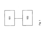
- Fig. 1 shows a block diagram of a communication entity, such as a master or a slave, for communication via a bus-oriented communication network with a controller 101 and a selector 103.
- the controller 101 may include a processor and / or firmware and / or hardware and eg a logic circuit based thereon ,
- the selector 103 generates a selection signal to select a first or a second communication bus sybsystem depending on an operation mode of the communication entity, which may be, for example, data, service or trouble-dependent.
- these subsystems are integrated for selection within the bused communication network and the communication entity, as shown below.
- the selection signal is forwarded to the control device which, in response thereto, in particular in the case of a processor device, for example, is set up program-technically in order to communicate in accordance with the first or the second communication bus subsystem.
- the communication entity can furthermore have a transmitter and / or a receiver for communication via the communication network, which in principle can also be wireless or wired.
- the communication entity which can work as a master, for example, in addition to a serial high-speed bus technology for a point-to-point communication subsystem
- a bus subsystem with the multidrop technology can be integrated in a master module.
- the overall functionality may be realized, for example, by predetermined mechanisms or logic circuits that may be implemented in both a master and slave communication entity.
- the main communication system is realized in the form of a point-to-point connection system, wherein the multidrop topology can be provided as a subsystem or as a fall-back system. This training is thus advantageous for applications in mechanical and plant engineering.
- the point-to-point connection system can be provided as a secondary system or as a fall-back system, in particular in the case of permanent disruptions of the multidrop topology.
- Fig. 2 shows two Kilunikationsbustopologien which can be realized with the communication entity according to the invention.
- Fig. 2a For example, a serial bus topology with a master 201 and a plurality of serially connected slaves 203 is shown.
- a connection 205 is provided, which the in Fig. 2a presented topology added to a ring topology.
- Fig. 2b shows a multidrop topology with a master 207 and a plurality of slaves 209, which may have, for example, the features of the communication entity according to the invention.
- a connection 211 can be provided which supplements the topology to form a ring topology.
- the communication entities are set up, in the context of both in Fig. 2 to work on presented topologies.
- the serial bus subsystem realized a bus system, which is provided for a transmission of, for example, process and parameter data as well as for the configuration and addressing of the bus system or the entities connected thereto. If it is intended to communicate only in accordance with this bus subsystem, this will also be referred to below as a first operating mode or as a first operating mode or also as operating mode A.
- This operating mode A essentially meets the requirements of mechanical engineering.
- a second operating mode or a second operating mode or a mode B for example, the in Fig.
- bus subsystem shown is used exclusively for transmitting process and / or parameter data, and only for the configuration and addressing of the bus system is the in Fig. 2a shown bus subsystem used.
- This operating mode B essentially meets the requirements of process technology.
- the invention it is also possible to respond to a combination of the modes A and B described above and corresponding selection and control of the first or second subsystem. So it is possible, for example, before the occurrence of a disturbance in Fig. 2a subsystem shown to be used during the operating mode A, wherein after an occurrence of a fault, the operating mode B with the in Fig. 2b represented subsystem can be used, or vice versa.
- Switching between the above-mentioned operating modes or modes can be carried out, for example, by the master, by the respective application or automatically by the further communication entities themselves.
- the in Fig. 2a shown bus system can be configured easily and quickly. If the hot-swapping property is required, it is possible, for example, to switch over to the multidrop bus subsystem in the case of a slave subscriber, which can also be realized, for example, by means of a change in the communication protocol. If the main system is functional again, it is possible, for example, to switch over again to the operating mode provided for the trouble-free case.
- a hybrid protocol structure is preferably used, which enables the transmission of process data via a parameter channel predetermined for this purpose.
- the respective additional connection 205 or 211 may be performed in the form of an example additional cable to the end of a modular input-output station to the availability of the system in case of failure electromechanical connection or a cable connection.
- a communication can be maintained uninterrupted.
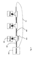
- Fig. 3 shows a bus communication system in which the in Fig. 2 shown subsystems are realized for different operating modes.
- a master 301 and a plurality of slaves 303 are provided, which preferably have the features of the communication entity according to the invention.
- the bus communication system includes a first wiring arrangement 305 for implementing the in Fig. 2b shown multidrop arrangement.
- a wiring arrangement 307 for implementing the in Fig. 2a illustrated point-to-point arrangement provided.
- Both the master 301 and the slaves 303 each have a plurality of terminals intended for the respective topology, which correspond to the in Fig. 3 allow shown wiring.
- Coupling members 309 may also be provided between the slaves, which allow a modular coupling of Medunikationsentmaschineen.
- a return connection 311 is optionally provided.
- the master and each slave expediently has in each case a hardware connection unit, for example a plug unit, which unites the respective connection contacts for the wiring arrangements of the two subsystems, so that consequently only the entire system can be seen from the outside.
- the coupling members thus unite appropriate, such as from Fig. 6 can be seen, for each coupling to a neighboring unit or arrangement respective necessary connection contacts for the two subsystems each within a common hardware connection unit, eg plug unit.
- Fig. 4 shows an embodiment of another bus system with a master 401 and a plurality of slaves 403, which may have, for example, the features of the communication entity according to the invention.
- the communication entities are coupled, for example by means of T-coupler 405 to the bus system.
- the bus system comprises a first wiring arrangement 407 for implementing a multidrop subsystem and a wiring arrangement 409 for implementing a point-to-point subsystem.
- the wiring arrangement 407 can for example be supplemented via an optional feedback branch 411 into a ring architecture and connected to the master 401. This in Fig. 4 illustrated bus system is particularly suitable for use in remote systems.
- the master and each slave expediently has only one hardware connection unit, which unites the respective connection contacts for the wiring arrangements of the two subsystems.
- the T-couplers which thus each have only one hardware connection unit for each coupling to a neighboring unit or arrangement, which unites the respective connection contacts for the two subsystems.
- each hardware connection unit expediently combines the respective connection contacts for the wiring arrangements of the two subsystems, thus only two complementary hardware connection units, eg a jack-type and a pin-type plug unit, are required for each coupling between two neighboring units or arrangements.
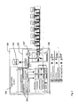
- Fig. 5 clarified using the in Fig. 3 shown bus topology a structure of a master 501, which preferably has the features of the communication entity according to the invention.
- the master 501 comprises a selector 503 with two outputs A and B, which are connected to a controller 505 for mode switching.
- the outputs A and B of the selector 503 are assigned, for example, to the modes A and B described above, and it is further possible to select between a configuration and address assignment and / or a transmission of process data or process parameters in each mode.
- the control device 505 has control subassemblies 506, which also enable a changeover to the operating mode B in the event of a fault during the operating mode A, or vice versa.
- control subassemblies 506 which also enable a changeover to the operating mode B in the event of a fault during the operating mode A, or vice versa.
- a structure of a master with a selector 503 and a control device 505 can be seen, which in the operating mode A or B cause a startup in phase I or phase II, being returned in phase II to a previously disturbed mode.
- Phase III indicates a fault condition.
- the master further comprises a memory 504 and a fault detector 507, which the Selector 503 informed of a fault.
- the connection contacts for both topologies are preferably integrated within a hardware connection unit, eg plug unit.
- the multidrop arrangement In case of an accident in the ring topology physics, for example, the multidrop arrangement is switched over. In the case of a malfunction in multidrop physics, for example, switching is made to ring topology physics. In the case of a failure of a slave with active ring topology physics, on the other hand, it switches to the multidrop topology, for example.
- the change of operation is initiated by the detector 507, which acts on the switch 508.
- the master preferably includes a common hardware connection unit for communicating over the first communication connection arrangement and communicating over the second communication connection arrangement.
- the switch 508 thus also ensures the connection between the data memory 504 and the bus subsystem to be actively connected for the data transmission. Any switchover, whether from the point-to-point topology or from the multidrop topology, can thus take place without data loss or while maintaining the consistency of the process image. Furthermore, the switchover expediently takes place automatically in the event of any malfunction of the active bus subsystem detected by the master, accompanied by simultaneous signaling of the selection device by a signaling signal via the effected changeover. Consequently, in the Essentially all freedoms are given for further diagnosis and fault management.
- Fig. 6 shows a construction of a slave with a slave logic 601, which is arranged in a plug-in housing 602, with different bus topologies, which is respectively associated with a transmission physics 604 and 606, and MAC elements 609 and 607 (MAC: Medium Access Control) ,
- the pluggable housing 602 comprises a common hardware connection unit for the connection contacts of both the transmission physics 604 and the transmission physics 606.
- the terminals 603 and 605 which are connected to the connection contacts of the transmission physics 604 and to the connection contacts of the transmission physics 606 for connecting the slave to be coupled to the overall system, integrated within a common hardware connection unit.
- the hardware connection unit of the pluggable housing 602 as a jack-type plug-in unit and the complementary hardware connection unit to be coupled thereto with the connection contacts 603 and 605 are thus in the form of a pin Plug unit formed.
- a slave also preferably includes a common hardware connection unit for communicating via the first communication connection arrangement and for communicating via the second communication connection arrangement.
Landscapes
- Engineering & Computer Science (AREA)
- Computer Networks & Wireless Communication (AREA)
- Signal Processing (AREA)
- Theoretical Computer Science (AREA)
- Physics & Mathematics (AREA)
- General Engineering & Computer Science (AREA)
- General Physics & Mathematics (AREA)
- Small-Scale Networks (AREA)
Claims (8)
- Système de communication par bus comprenant une pluralité d'entités de communication, lesquelles présentent à chaque fois un dispositif de commande (101) et un dispositif de sélection (103), le dispositif de commande (101) étant conçu pour communiquer par le biais du réseau de communication orienté bus en réaction à un signal de sélection selon un premier sous-système de bus de communication ou selon un second sous-système de bus de communication, et le dispositif de sélection (103) étant conçu pour générer le signal de sélection en fonction d'un mode de service de l'entité de communication, afin de sélectionner le premier sous-système de bus de communication ou le second sous-système de bus de communication, le premier sous-système de communication étant un système point à point et le second sous-système de communication étant un système multipoint, et lesquelles sont aménagées pour communiquer par le biais d'un réseau de communication orienté bus, une entité de communication de la pluralité des entités de communication étant installée comme une entité maître et les autres entités de communication de la pluralité des entités de communication étant installées comme entités esclaves, de sorte que chaque entité esclave peut communiquer également directement avec l'entité maître.
- Système de communication par bus selon la revendication 1, qui comprend un premier dispositif de câblage pour la liaison des entités de communication selon le premier sous-système de communication et un second dispositif de câblage pour la liaison des entités de communication selon le second sous-système de communication.
- Système de communication par bus selon la revendication 1 ou 2, qui présente également une pluralité d'éléments de couplage pour le couplage modulaire des entités de communication selon le premier sous-système de communication et selon le second sous-système de communication.
- Système de communication par bus selon la revendication 1 ou 2, qui présente également une pluralité d'éléments de couplage en T, pour le couplage modulaire des entités de communication selon le premier sous-système de communication et selon le second sous-système de communication.
- Système de communication par bus selon l'une quelconque des revendications précédentes, une liaison étant prévue pour compléter le premier sous-système de communication ou le second sous-système de communication avec un sous-système de communication annulaire.
- Système de communication par bus selon la revendication 1, le mode de service comprenant un premier mode de service avec des phases de service pour la configuration et l'adressage du réseau de communication orienté bus et des entités de communication pouvant être raccordées au réseau et pour la transmission de données de processus et de données de paramètre, et un second mode de service avec des phases de service pour la configuration et l'adressage du réseau de communication orienté bus et d'entités de communication pouvant être raccordées au réseau et pour la transmission de données de processus et de données de paramètre, et le dispositif de sélection étant conçu pour sélectionner dans le premier mode de service de préférence le premier sous-système de communication et dans le second mode de service de préférence le second sous-système de communication pour la transmission de données de processus et de données de paramètre, en particulier exclusivement pour la transmission de données de processus et de données de paramètre.
- Système de communication par bus selon la revendication 1, le dispositif de sélection (103) étant conçu pour sélectionner le premier sous-système de communication dans le premier mode de service sans incident et le second sous-système de communication dans le premier mode de service perturbé.
- Système de communication par bus selon la revendication 1, l'entité de communication comprenant une unité commune de raccordement de matériel pour la communication par le premier sous-système de communication et pour la communication par le second sous-système de communication.
Applications Claiming Priority (1)
| Application Number | Priority Date | Filing Date | Title |
|---|---|---|---|
| DE102008050102A DE102008050102B4 (de) | 2008-10-06 | 2008-10-06 | Kommunikationsentität zur Kommunikation über ein busorientiertes Kommunikationsnetzwerk |
Publications (2)
| Publication Number | Publication Date |
|---|---|
| EP2173065A1 EP2173065A1 (fr) | 2010-04-07 |
| EP2173065B1 true EP2173065B1 (fr) | 2011-11-09 |
Family
ID=41382154
Family Applications (1)
| Application Number | Title | Priority Date | Filing Date |
|---|---|---|---|
| EP09012189A Not-in-force EP2173065B1 (fr) | 2008-10-06 | 2009-09-25 | Entité de communication pour la communication sur un réseau de communication du type bus |
Country Status (5)
| Country | Link |
|---|---|
| US (1) | US8473656B2 (fr) |
| EP (1) | EP2173065B1 (fr) |
| AT (1) | ATE533260T1 (fr) |
| DE (1) | DE102008050102B4 (fr) |
| ES (1) | ES2371705T3 (fr) |
Families Citing this family (30)
| Publication number | Priority date | Publication date | Assignee | Title |
|---|---|---|---|---|
| CN102393762A (zh) * | 2011-08-30 | 2012-03-28 | 上海三一精机有限公司 | 一种用于数控系统电机主轴转速的控制系统及方法 |
| WO2013064866A1 (fr) | 2011-11-04 | 2013-05-10 | Freescale Semiconductor, Inc. | Module de réseau distribué en temps réel, réseau distribué en temps réel et procédé associé |
| EP2774337B1 (fr) | 2011-11-04 | 2020-03-25 | NXP USA, Inc. | Dispositif esclave de réseau distribué en temps réel, réseau distribué en temps réel et procédé correspondant |
| US20130173868A1 (en) * | 2011-12-29 | 2013-07-04 | Texas Instruments Incorporated | Generation of Activation List for Memory Translation and Memory Access Protection in Industrial Ethernet Standard |
| KR101596078B1 (ko) * | 2012-06-12 | 2016-02-26 | 엘에스산전 주식회사 | 캔오픈 네트워크의 구성 방법, 캔오픈 네트워크의 슬레이브 장치의 동작 방법 및 캔오픈 네트워크를 이용한 피엘씨 장치 제어 시스템 |
| WO2014006446A1 (fr) | 2012-07-02 | 2014-01-09 | Freescale Semiconductor, Inc. | Réacheminement de paquets ethercat à synchronisation répartie |
| EP2713563B1 (fr) * | 2012-09-28 | 2017-08-02 | Siemens Aktiengesellschaft | Système de communication industriel pouvant fonctionner de manière redondante, appareil de communication et procédé de fonctionnement redondant d'un système de communication industriel |
| WO2014083381A1 (fr) | 2012-11-27 | 2014-06-05 | Freescale Semiconductor, Inc. | Système redondant de transmission de paquet |
| DE102014105207B4 (de) * | 2014-04-11 | 2015-10-22 | Beckhoff Automation Gmbh | Verfahren zum Betreiben eines Kommunikationsnetzwerks und Kommunikationsnetzwerk |
| CN104133447A (zh) * | 2014-07-28 | 2014-11-05 | 上海华兴数字科技有限公司 | 一种工程机械控制系统及工程机械 |
| DE102015121290A1 (de) | 2015-12-07 | 2017-06-08 | Eaton Electrical Ip Gmbh & Co. Kg | Busanordnung mit einem Teilnehmer mit Modulen und Verfahren zum Betreiben einer Busanordnung |
| DE102015121288A1 (de) * | 2015-12-07 | 2017-06-08 | Eaton Electrical Ip Gmbh & Co. Kg | Busanordnung und Verfahren zum Betreiben einer Busanordnung |
| DE102016103928A1 (de) * | 2016-03-04 | 2017-09-07 | Eaton Electrical Ip Gmbh & Co. Kg | Busanordnung und Verfahren zum Betreiben einer Busanordnung |
| DE102016212198B4 (de) * | 2016-07-05 | 2024-01-25 | Robert Bosch Gmbh | Modulares system und verfahren zur kommunikation in einem solchen modularen system |
| DE102016212291A1 (de) * | 2016-07-06 | 2018-01-11 | Robert Bosch Gmbh | Modulares gerät für ein modulares system und verfahren zur kommunikation in einem solchen modularen system |
| WO2018079880A1 (fr) * | 2016-10-28 | 2018-05-03 | 주식회사 엘앤비기술 | Dispositif d'adresse publique utilisant une communication can |
| CN106603188A (zh) * | 2016-12-30 | 2017-04-26 | 深圳市英威腾电气股份有限公司 | 一种变频器接口装置 |
| EP3388902B1 (fr) * | 2017-04-10 | 2026-02-18 | Siemens Aktiengesellschaft | Système d'automatisation sécurisée |
| DE102017214893A1 (de) * | 2017-08-25 | 2019-02-28 | Lenze Automation Gmbh | Verfahren zum Betreiben eines EtherCAT-Feldbussystems und EtherCAT-Feldbussystem |
| CN107707447B (zh) * | 2017-09-22 | 2020-10-23 | 中科新松有限公司 | 一种基于EtherCAT的从站系统及控制方法 |
| CN107948282A (zh) * | 2017-11-24 | 2018-04-20 | 杰克缝纫机股份有限公司 | 一种基于工业以太网的缝纫机控制方法及系统 |
| FR3076162B1 (fr) * | 2017-12-22 | 2019-12-13 | Luos Robotics | Systeme de communication decentralise et procede de commande correspondant |
| US10474622B1 (en) * | 2018-07-16 | 2019-11-12 | Qualcomm Incorporated | Method and apparatus for latency management of data communication over serial bus |
| CN109525472B (zh) * | 2018-09-30 | 2021-05-14 | 大族激光科技产业集团股份有限公司 | 一种总线通讯转换电路、装置及系统 |
| KR20220021446A (ko) * | 2019-06-21 | 2022-02-22 | 루오 | 분산 통신 시스템 및 동 시스템 제어 방법 |
| KR102820281B1 (ko) | 2019-09-09 | 2025-06-16 | 엘지이노텍 주식회사 | 차량 내부 통신 시스템 및 이를 포함하는 차량 |
| DE102019217002A1 (de) * | 2019-11-05 | 2021-05-06 | Zf Friedrichshafen Ag | Fahrzeugsteuerungsvorrichtung, Fahrzeugsteuerungsverfahren sowie Fahrzeug |
| CN111858437B (zh) * | 2020-07-31 | 2022-06-28 | 上海海得控制系统股份有限公司 | 基于双总线的热插拔处理方法、装置、存储介质及电子设备 |
| CN112147927B (zh) * | 2020-09-11 | 2022-02-11 | 苏州谷夫道自动化科技有限公司 | 一种双通道总线通信的多轴运动控制系统 |
| CN119537306B (zh) * | 2025-01-23 | 2025-08-12 | 深圳腾信百纳科技有限公司 | 一种基于硬实时通用mpu板级模组 |
Family Cites Families (21)
| Publication number | Priority date | Publication date | Assignee | Title |
|---|---|---|---|---|
| JPS6194433A (ja) * | 1984-10-15 | 1986-05-13 | Mitsubishi Electric Corp | シリアルバスの制御方式 |
| US5793993A (en) * | 1995-01-26 | 1998-08-11 | General Magic, Inc. | Method for transmitting bus commands and data over two wires of a serial bus |
| DE19509558A1 (de) * | 1995-03-16 | 1996-09-19 | Abb Patent Gmbh | Verfahren zur fehlertoleranten Kommunikation unter hohen Echtzeitbedingungen |
| US5914957A (en) * | 1996-12-19 | 1999-06-22 | Otis Elevator Company | Automatic node configuration with identical nodes |
| DE19714761A1 (de) * | 1997-04-10 | 1998-10-15 | Bosch Gmbh Robert | Datenkommunikationsverbindung in hierarchischem Kommunikationsnetz mit Bus, die nach einem Abfrage/Antwort-Protokoll, dem sogenannten Polling-Protokoll, betrieben wird |
| US7020076B1 (en) * | 1999-10-26 | 2006-03-28 | California Institute Of Technology | Fault-tolerant communication channel structures |
| DE10047923C2 (de) * | 2000-09-27 | 2003-04-10 | Siemens Ag | Verfahren zur Erzeugung einer Verbindungs-Redundanz für ein serielles Kommunikationssystem mit einer Mastereinheit und einer Mehrzahl von Slaveeinheiten, die untereinander als Aneinanderreihung von Punkt-zu-Punkt-Verbindungen in Linientopologie verbunden sind, sowie korrespondierendes serielles Kommunikationssystem |
| US6934785B2 (en) * | 2000-12-22 | 2005-08-23 | Micron Technology, Inc. | High speed interface with looped bus |
| GB0213197D0 (en) * | 2002-06-10 | 2002-07-17 | Cnh Belgium Nv | Vehicle control system and apparatus therefor |
| WO2006079901A1 (fr) * | 2005-01-26 | 2006-08-03 | Nokia Corporation | Procede, appareil et produit programme informatique assurant l'identification d'un dispositif par une architecture de bus multipoint/en anneau configurable |
| US7380042B2 (en) * | 2005-11-22 | 2008-05-27 | Dell Products L.P. | Method of detecting and monitoring master device communication on system bus |
| US7685392B2 (en) * | 2005-11-28 | 2010-03-23 | International Business Machines Corporation | Providing indeterminate read data latency in a memory system |
| JP4656421B2 (ja) * | 2006-02-28 | 2011-03-23 | 株式会社デンソー | バス通信システム |
| DE102006019305A1 (de) * | 2006-04-26 | 2007-10-31 | Robert Bosch Gmbh | Verfahren zur Datenübertragung von und zu einem Steuergerät |
| US7529343B2 (en) * | 2006-05-04 | 2009-05-05 | The Boeing Company | System and method for improved field of view X-ray imaging using a non-stationary anode |
| US7920588B2 (en) * | 2006-05-22 | 2011-04-05 | Edgewater Computer Systems, Inc. | Data communications system and method of data transmission |
| US7865756B2 (en) * | 2007-03-12 | 2011-01-04 | Mosaid Technologies Incorporated | Methods and apparatus for clock signal synchronization in a configuration of series-connected semiconductor devices |
| DE102007044816B3 (de) * | 2007-09-20 | 2009-04-30 | Insta Elektro Gmbh | Verfahren zum Betrieb eines Bussystems |
| CN101478577A (zh) * | 2008-01-03 | 2009-07-08 | 鸿富锦精密工业(深圳)有限公司 | 主设备对从设备的定址系统及方法 |
| CN101499046A (zh) * | 2008-01-30 | 2009-08-05 | 鸿富锦精密工业(深圳)有限公司 | Spi设备通信电路 |
| US8095747B2 (en) * | 2008-09-26 | 2012-01-10 | Cypress Semiconductor Corporation | Memory system and method |
-
2008
- 2008-10-06 DE DE102008050102A patent/DE102008050102B4/de not_active Expired - Fee Related
-
2009
- 2009-09-25 EP EP09012189A patent/EP2173065B1/fr not_active Not-in-force
- 2009-09-25 AT AT09012189T patent/ATE533260T1/de active
- 2009-09-25 ES ES09012189T patent/ES2371705T3/es active Active
- 2009-09-29 US US12/568,859 patent/US8473656B2/en not_active Expired - Fee Related
Also Published As
| Publication number | Publication date |
|---|---|
| DE102008050102B4 (de) | 2010-11-04 |
| EP2173065A1 (fr) | 2010-04-07 |
| US20100088442A1 (en) | 2010-04-08 |
| ES2371705T3 (es) | 2012-01-09 |
| DE102008050102A1 (de) | 2010-04-08 |
| US8473656B2 (en) | 2013-06-25 |
| ATE533260T1 (de) | 2011-11-15 |
Similar Documents
| Publication | Publication Date | Title |
|---|---|---|
| EP2173065B1 (fr) | Entité de communication pour la communication sur un réseau de communication du type bus | |
| DE69715443T2 (de) | Vermittlungssystem für sicherheitsübertragung | |
| DE102006061063B4 (de) | Redundantes Überwachungssteuersystem, und Redundanzschaltverfahren des Gleichen | |
| EP2098019B1 (fr) | Système de communication présentant une structure maître-esclave | |
| EP2014025B1 (fr) | Unité d'interface et système de communication à structure maître-esclave | |
| EP1657608B1 (fr) | Procédé et appareil pour actionner d'un réseau | |
| DE102012209108B4 (de) | Netzwerkeinrichtung, Netzwerkanordnung und Verfahren zum Betreiben einer Netzwerkanordnung | |
| DE102006055889B3 (de) | Kommunikationssystem mit einer Master-Slave-Struktur | |
| EP1869836B1 (fr) | Unite maitre, systeme de communication et procede pour les faire fonctionner | |
| EP1814266B1 (fr) | Réseau de communication redondant | |
| DE102016000126A1 (de) | Serielles Bussystem mit Koppelmodulen | |
| EP1193916A2 (fr) | Redondace de liaison pour système de communication en série | |
| DE10302485B4 (de) | Feldbusanschaltung in Schaltanlagen | |
| DE102019203352A1 (de) | Verfahren und Vorrichtung zum Betreiben eines Kommunikationssystems | |
| DE102008037610A1 (de) | Vorrichtung und Verfahren zur wahlweisen Umschaltung zweier Master für zugeordnete Slaves | |
| DE112004000018B4 (de) | Signalrelaiseinrichtung in einem optischen Kommunikationssystem sowie optisches Kommunikationssystem | |
| DE10343615A1 (de) | Netzknoten für ein optisches Nachrichtenübertragungsnetz | |
| DE102015208836B4 (de) | Vorrichtung, System und Verfahren zur Kommunikationsbussteuerung | |
| DE102009043629B4 (de) | Serielle Busstruktur | |
| DE60215910T2 (de) | Verfahren zur Bestimmung einer aktiven oder passiven Rollenzuteilung für ein Netzelementsteuerungsmittel | |
| EP3036862B1 (fr) | Procédé d'exploitation d'un réseau et élément participant d'un réseau | |
| EP2817923B1 (fr) | Réseau de calculateurs avec un bus de liaison de forme annulaire | |
| DE102011115431B4 (de) | Feldbusnetzwerkadapter und Feldbusnetzwerkteilnehmer mit Feldbusanschlüssen | |
| EP3824393B1 (fr) | Circuit de transmission de données avec mise en mémoire tampon | |
| WO2026093257A1 (fr) | Dispositif de communication et procédé d'exploitation d'un dispositif de communication |
Legal Events
| Date | Code | Title | Description |
|---|---|---|---|
| PUAI | Public reference made under article 153(3) epc to a published international application that has entered the european phase |
Free format text: ORIGINAL CODE: 0009012 |
|
| AK | Designated contracting states |
Kind code of ref document: A1 Designated state(s): AT BE BG CH CY CZ DE DK EE ES FI FR GB GR HR HU IE IS IT LI LT LU LV MC MK MT NL NO PL PT RO SE SI SK SM TR |
|
| AX | Request for extension of the european patent |
Extension state: AL BA RS |
|
| 17P | Request for examination filed |
Effective date: 20100915 |
|
| GRAP | Despatch of communication of intention to grant a patent |
Free format text: ORIGINAL CODE: EPIDOSNIGR1 |
|
| RIC1 | Information provided on ipc code assigned before grant |
Ipc: H04L 12/40 20060101AFI20110415BHEP |
|
| GRAS | Grant fee paid |
Free format text: ORIGINAL CODE: EPIDOSNIGR3 |
|
| GRAA | (expected) grant |
Free format text: ORIGINAL CODE: 0009210 |
|
| AK | Designated contracting states |
Kind code of ref document: B1 Designated state(s): AT BE BG CH CY CZ DE DK EE ES FI FR GB GR HR HU IE IS IT LI LT LU LV MC MK MT NL NO PL PT RO SE SI SK SM TR |
|
| REG | Reference to a national code |
Ref country code: GB Ref legal event code: FG4D Free format text: NOT ENGLISH |
|
| REG | Reference to a national code |
Ref country code: CH Ref legal event code: EP Ref country code: CH Ref legal event code: NV Representative=s name: BOVARD AG |
|
| REG | Reference to a national code |
Ref country code: IE Ref legal event code: FG4D Free format text: LANGUAGE OF EP DOCUMENT: GERMAN |
|
| REG | Reference to a national code |
Ref country code: DE Ref legal event code: R096 Ref document number: 502009001863 Country of ref document: DE Effective date: 20120105 |
|
| REG | Reference to a national code |
Ref country code: ES Ref legal event code: FG2A Ref document number: 2371705 Country of ref document: ES Kind code of ref document: T3 Effective date: 20120109 |
|
| REG | Reference to a national code |
Ref country code: NL Ref legal event code: T3 |
|
| LTIE | Lt: invalidation of european patent or patent extension |
Effective date: 20111109 |
|
| PG25 | Lapsed in a contracting state [announced via postgrant information from national office to epo] |
Ref country code: NO Free format text: LAPSE BECAUSE OF FAILURE TO SUBMIT A TRANSLATION OF THE DESCRIPTION OR TO PAY THE FEE WITHIN THE PRESCRIBED TIME-LIMIT Effective date: 20120209 Ref country code: LT Free format text: LAPSE BECAUSE OF FAILURE TO SUBMIT A TRANSLATION OF THE DESCRIPTION OR TO PAY THE FEE WITHIN THE PRESCRIBED TIME-LIMIT Effective date: 20111109 Ref country code: IS Free format text: LAPSE BECAUSE OF FAILURE TO SUBMIT A TRANSLATION OF THE DESCRIPTION OR TO PAY THE FEE WITHIN THE PRESCRIBED TIME-LIMIT Effective date: 20120309 |
|
| PG25 | Lapsed in a contracting state [announced via postgrant information from national office to epo] |
Ref country code: PL Free format text: LAPSE BECAUSE OF FAILURE TO SUBMIT A TRANSLATION OF THE DESCRIPTION OR TO PAY THE FEE WITHIN THE PRESCRIBED TIME-LIMIT Effective date: 20111109 Ref country code: HR Free format text: LAPSE BECAUSE OF FAILURE TO SUBMIT A TRANSLATION OF THE DESCRIPTION OR TO PAY THE FEE WITHIN THE PRESCRIBED TIME-LIMIT Effective date: 20111109 Ref country code: SE Free format text: LAPSE BECAUSE OF FAILURE TO SUBMIT A TRANSLATION OF THE DESCRIPTION OR TO PAY THE FEE WITHIN THE PRESCRIBED TIME-LIMIT Effective date: 20111109 Ref country code: PT Free format text: LAPSE BECAUSE OF FAILURE TO SUBMIT A TRANSLATION OF THE DESCRIPTION OR TO PAY THE FEE WITHIN THE PRESCRIBED TIME-LIMIT Effective date: 20120309 Ref country code: SI Free format text: LAPSE BECAUSE OF FAILURE TO SUBMIT A TRANSLATION OF THE DESCRIPTION OR TO PAY THE FEE WITHIN THE PRESCRIBED TIME-LIMIT Effective date: 20111109 Ref country code: LV Free format text: LAPSE BECAUSE OF FAILURE TO SUBMIT A TRANSLATION OF THE DESCRIPTION OR TO PAY THE FEE WITHIN THE PRESCRIBED TIME-LIMIT Effective date: 20111109 Ref country code: GR Free format text: LAPSE BECAUSE OF FAILURE TO SUBMIT A TRANSLATION OF THE DESCRIPTION OR TO PAY THE FEE WITHIN THE PRESCRIBED TIME-LIMIT Effective date: 20120210 |
|
| REG | Reference to a national code |
Ref country code: IE Ref legal event code: FD4D |
|
| PG25 | Lapsed in a contracting state [announced via postgrant information from national office to epo] |
Ref country code: CY Free format text: LAPSE BECAUSE OF FAILURE TO SUBMIT A TRANSLATION OF THE DESCRIPTION OR TO PAY THE FEE WITHIN THE PRESCRIBED TIME-LIMIT Effective date: 20111109 |
|
| PG25 | Lapsed in a contracting state [announced via postgrant information from national office to epo] |
Ref country code: SK Free format text: LAPSE BECAUSE OF FAILURE TO SUBMIT A TRANSLATION OF THE DESCRIPTION OR TO PAY THE FEE WITHIN THE PRESCRIBED TIME-LIMIT Effective date: 20111109 Ref country code: IE Free format text: LAPSE BECAUSE OF FAILURE TO SUBMIT A TRANSLATION OF THE DESCRIPTION OR TO PAY THE FEE WITHIN THE PRESCRIBED TIME-LIMIT Effective date: 20111109 Ref country code: DK Free format text: LAPSE BECAUSE OF FAILURE TO SUBMIT A TRANSLATION OF THE DESCRIPTION OR TO PAY THE FEE WITHIN THE PRESCRIBED TIME-LIMIT Effective date: 20111109 Ref country code: CZ Free format text: LAPSE BECAUSE OF FAILURE TO SUBMIT A TRANSLATION OF THE DESCRIPTION OR TO PAY THE FEE WITHIN THE PRESCRIBED TIME-LIMIT Effective date: 20111109 Ref country code: BG Free format text: LAPSE BECAUSE OF FAILURE TO SUBMIT A TRANSLATION OF THE DESCRIPTION OR TO PAY THE FEE WITHIN THE PRESCRIBED TIME-LIMIT Effective date: 20120209 Ref country code: EE Free format text: LAPSE BECAUSE OF FAILURE TO SUBMIT A TRANSLATION OF THE DESCRIPTION OR TO PAY THE FEE WITHIN THE PRESCRIBED TIME-LIMIT Effective date: 20111109 |
|
| PG25 | Lapsed in a contracting state [announced via postgrant information from national office to epo] |
Ref country code: RO Free format text: LAPSE BECAUSE OF FAILURE TO SUBMIT A TRANSLATION OF THE DESCRIPTION OR TO PAY THE FEE WITHIN THE PRESCRIBED TIME-LIMIT Effective date: 20111109 |
|
| PLBE | No opposition filed within time limit |
Free format text: ORIGINAL CODE: 0009261 |
|
| STAA | Information on the status of an ep patent application or granted ep patent |
Free format text: STATUS: NO OPPOSITION FILED WITHIN TIME LIMIT |
|
| 26N | No opposition filed |
Effective date: 20120810 |
|
| REG | Reference to a national code |
Ref country code: DE Ref legal event code: R097 Ref document number: 502009001863 Country of ref document: DE Effective date: 20120810 |
|
| PG25 | Lapsed in a contracting state [announced via postgrant information from national office to epo] |
Ref country code: MC Free format text: LAPSE BECAUSE OF NON-PAYMENT OF DUE FEES Effective date: 20120930 |
|
| PG25 | Lapsed in a contracting state [announced via postgrant information from national office to epo] |
Ref country code: FI Free format text: LAPSE BECAUSE OF FAILURE TO SUBMIT A TRANSLATION OF THE DESCRIPTION OR TO PAY THE FEE WITHIN THE PRESCRIBED TIME-LIMIT Effective date: 20111109 |
|
| PG25 | Lapsed in a contracting state [announced via postgrant information from national office to epo] |
Ref country code: MT Free format text: LAPSE BECAUSE OF FAILURE TO SUBMIT A TRANSLATION OF THE DESCRIPTION OR TO PAY THE FEE WITHIN THE PRESCRIBED TIME-LIMIT Effective date: 20111109 |
|
| PG25 | Lapsed in a contracting state [announced via postgrant information from national office to epo] |
Ref country code: TR Free format text: LAPSE BECAUSE OF FAILURE TO SUBMIT A TRANSLATION OF THE DESCRIPTION OR TO PAY THE FEE WITHIN THE PRESCRIBED TIME-LIMIT Effective date: 20111109 |
|
| PG25 | Lapsed in a contracting state [announced via postgrant information from national office to epo] |
Ref country code: SM Free format text: LAPSE BECAUSE OF FAILURE TO SUBMIT A TRANSLATION OF THE DESCRIPTION OR TO PAY THE FEE WITHIN THE PRESCRIBED TIME-LIMIT Effective date: 20111109 Ref country code: LU Free format text: LAPSE BECAUSE OF NON-PAYMENT OF DUE FEES Effective date: 20120925 |
|
| PG25 | Lapsed in a contracting state [announced via postgrant information from national office to epo] |
Ref country code: HU Free format text: LAPSE BECAUSE OF FAILURE TO SUBMIT A TRANSLATION OF THE DESCRIPTION OR TO PAY THE FEE WITHIN THE PRESCRIBED TIME-LIMIT Effective date: 20090925 |
|
| PG25 | Lapsed in a contracting state [announced via postgrant information from national office to epo] |
Ref country code: MK Free format text: LAPSE BECAUSE OF FAILURE TO SUBMIT A TRANSLATION OF THE DESCRIPTION OR TO PAY THE FEE WITHIN THE PRESCRIBED TIME-LIMIT Effective date: 20111109 |
|
| REG | Reference to a national code |
Ref country code: FR Ref legal event code: PLFP Year of fee payment: 7 |
|
| PGFP | Annual fee paid to national office [announced via postgrant information from national office to epo] |
Ref country code: CH Payment date: 20150924 Year of fee payment: 7 Ref country code: ES Payment date: 20150924 Year of fee payment: 7 Ref country code: GB Payment date: 20150924 Year of fee payment: 7 |
|
| PGFP | Annual fee paid to national office [announced via postgrant information from national office to epo] |
Ref country code: FR Payment date: 20150924 Year of fee payment: 7 Ref country code: AT Payment date: 20150930 Year of fee payment: 7 |
|
| PGFP | Annual fee paid to national office [announced via postgrant information from national office to epo] |
Ref country code: IT Payment date: 20150930 Year of fee payment: 7 |
|
| PGFP | Annual fee paid to national office [announced via postgrant information from national office to epo] |
Ref country code: NL Payment date: 20150921 Year of fee payment: 7 Ref country code: BE Payment date: 20150921 Year of fee payment: 7 |
|
| PG25 | Lapsed in a contracting state [announced via postgrant information from national office to epo] |
Ref country code: BE Free format text: LAPSE BECAUSE OF NON-PAYMENT OF DUE FEES Effective date: 20160930 |
|
| REG | Reference to a national code |
Ref country code: CH Ref legal event code: PL |
|
| REG | Reference to a national code |
Ref country code: NL Ref legal event code: MM Effective date: 20161001 |
|
| REG | Reference to a national code |
Ref country code: AT Ref legal event code: MM01 Ref document number: 533260 Country of ref document: AT Kind code of ref document: T Effective date: 20160925 |
|
| GBPC | Gb: european patent ceased through non-payment of renewal fee |
Effective date: 20160925 |
|
| PG25 | Lapsed in a contracting state [announced via postgrant information from national office to epo] |
Ref country code: NL Free format text: LAPSE BECAUSE OF NON-PAYMENT OF DUE FEES Effective date: 20161001 |
|
| REG | Reference to a national code |
Ref country code: FR Ref legal event code: ST Effective date: 20170531 |
|
| PG25 | Lapsed in a contracting state [announced via postgrant information from national office to epo] |
Ref country code: GB Free format text: LAPSE BECAUSE OF NON-PAYMENT OF DUE FEES Effective date: 20160925 Ref country code: FR Free format text: LAPSE BECAUSE OF NON-PAYMENT OF DUE FEES Effective date: 20160930 Ref country code: LI Free format text: LAPSE BECAUSE OF NON-PAYMENT OF DUE FEES Effective date: 20160930 Ref country code: CH Free format text: LAPSE BECAUSE OF NON-PAYMENT OF DUE FEES Effective date: 20160930 |
|
| PG25 | Lapsed in a contracting state [announced via postgrant information from national office to epo] |
Ref country code: AT Free format text: LAPSE BECAUSE OF NON-PAYMENT OF DUE FEES Effective date: 20160925 Ref country code: IT Free format text: LAPSE BECAUSE OF NON-PAYMENT OF DUE FEES Effective date: 20160925 |
|
| REG | Reference to a national code |
Ref country code: BE Ref legal event code: MM Effective date: 20160930 |
|
| PG25 | Lapsed in a contracting state [announced via postgrant information from national office to epo] |
Ref country code: ES Free format text: LAPSE BECAUSE OF NON-PAYMENT OF DUE FEES Effective date: 20160926 |
|
| REG | Reference to a national code |
Ref country code: ES Ref legal event code: FD2A Effective date: 20181120 |
|
| P01 | Opt-out of the competence of the unified patent court (upc) registered |
Effective date: 20230424 |
|
| PGFP | Annual fee paid to national office [announced via postgrant information from national office to epo] |
Ref country code: DE Payment date: 20231127 Year of fee payment: 15 |
|
| REG | Reference to a national code |
Ref country code: DE Ref legal event code: R119 Ref document number: 502009001863 Country of ref document: DE |
|
| PG25 | Lapsed in a contracting state [announced via postgrant information from national office to epo] |
Ref country code: DE Free format text: LAPSE BECAUSE OF NON-PAYMENT OF DUE FEES Effective date: 20250401 |