EP2173959B1 - Procédé et dispositif de commande d'une installation de forage de roche - Google Patents
Procédé et dispositif de commande d'une installation de forage de roche Download PDFInfo
- Publication number
- EP2173959B1 EP2173959B1 EP07809887.8A EP07809887A EP2173959B1 EP 2173959 B1 EP2173959 B1 EP 2173959B1 EP 07809887 A EP07809887 A EP 07809887A EP 2173959 B1 EP2173959 B1 EP 2173959B1
- Authority
- EP
- European Patent Office
- Prior art keywords
- feed
- rock
- pressure
- control
- rig
- Prior art date
- Legal status (The legal status is an assumption and is not a legal conclusion. Google has not performed a legal analysis and makes no representation as to the accuracy of the status listed.)
- Active
Links
Images

Classifications
-
- E—FIXED CONSTRUCTIONS
- E21—EARTH OR ROCK DRILLING; MINING
- E21B—EARTH OR ROCK DRILLING; OBTAINING OIL, GAS, WATER, SOLUBLE OR MELTABLE MATERIALS OR A SLURRY OF MINERALS FROM WELLS
- E21B7/00—Special methods or apparatus for drilling
- E21B7/02—Drilling rigs characterised by means for land transport with their own drive, e.g. skid mounting or wheel mounting
- E21B7/022—Control of the drilling operation; Hydraulic or pneumatic means for activation or operation
-
- E—FIXED CONSTRUCTIONS
- E21—EARTH OR ROCK DRILLING; MINING
- E21B—EARTH OR ROCK DRILLING; OBTAINING OIL, GAS, WATER, SOLUBLE OR MELTABLE MATERIALS OR A SLURRY OF MINERALS FROM WELLS
- E21B44/00—Automatic control systems specially adapted for drilling operations, i.e. self-operating systems which function to carry out or modify a drilling operation without intervention of a human operator, e.g. computer-controlled drilling systems; Systems specially adapted for monitoring a plurality of drilling variables or conditions
- E21B44/02—Automatic control of the tool feed
-
- E—FIXED CONSTRUCTIONS
- E21—EARTH OR ROCK DRILLING; MINING
- E21B—EARTH OR ROCK DRILLING; OBTAINING OIL, GAS, WATER, SOLUBLE OR MELTABLE MATERIALS OR A SLURRY OF MINERALS FROM WELLS
- E21B7/00—Special methods or apparatus for drilling
- E21B7/02—Drilling rigs characterised by means for land transport with their own drive, e.g. skid mounting or wheel mounting
- E21B7/025—Rock drills, i.e. jumbo drills
Definitions
- the invention concerns a method and a device for controlling a rock drill rig which includes a carrier vehicle with at least one feed-beam, whereon a drilling machine is movable to and fro, wherein parameters for drill rig control are set by a control unit, and wherein each one of a plurality of operating modes includes specified operating settings for different operating parameters of the rig.
- WO 2006/089367 A1 discloses such a closest prior art method and device. From US 2005/0211468 A1 it is known to control drilling parameters due to selection of a bit size.
- a shock wave is generated by the percussive mechanism of the drilling machine. This shock wave is transmitted as an energy stress wave through the drill rod down to the drill bit.
- the stress wave reaches the drill bit, its hard metal button elements are pushed against the rock with such a strong force that the rock is fractured.
- the drill rod is rotated by means of a rotator including a rotation motor (often hydraulically driven) and a transmission. Rock dust is continuously removed from the front side of the drill bit by flushing.
- the drilling machine is mounted on a cradle, which is movable to and fro on a feed-beam.
- the drilling machine and the slide are driven.towards the rock along the feed-beam by means of a feed motor which can be a hydraulic cylinder or a chain feeder.
- a new drill rig When a new drill rig is delivered to a buyer, it is set with basic settings with respect to the drilling or operating parameters of the drill rig. These parameters are i.a. pressure and hydraulic flow levels for the different components of the rig. Further, the characteristics for the operating functions of the rig which concerns how the rig will be controlled during or react to differently sensed operating conditions are set.
- the basic setting of a new drill rig is normally tuned to the operating conditions that prevail in an intended area of use of the rig and possibly to the requirements of the user. If the drill rig is moved to another site with other drilling conditions or, more generally, during considerable variations of the conditions for drilling, the parameters should be adjusted to be set differently in order to adapt to these new conditions in order for the drilling to be as efficient as possible.
- Adjustments, of rig settings are normally carried out manually by a technician and in some cases by the rig operator, whereby a plurality of parameters affecting the percussive mechanism, the rotation motor, the feed motor etc. of the drilling machine are set.
- a problem with manual setting of parameters is that it is very complex to correctly provide a modern drill rig with the accurate parameter settings, since altering one parameter can affect the conditions for one or a plurality of other parameters.
- the feed force and the rotation torque need to be balanced to each other to sustain an efficient drilling operation. Lack of such balance because of altered rock formation conditions may more easily lead to jamming problems.
- the aims of the present invention are to provide a method and a device wherein the draw-backs of the background art are at least reduced.
- the drill rig is guaranteed to be tuned and set in the direction of, as much as possible, being optimized for operating in a particular type of rock.
- the operating parameters will be set in order to be adapted to the prevailing drilling situation.
- the settings are also tuned to each other such that the settings co-act and do not counter-act each other, which could otherwise easily be the case with manually set systems.
- a high percussion pressure together with low feed force could be harmful to the equipment in certain conditions. I.a. such unwanted combinations can be avoided through the invention.
- Said operating parameters are preferably a plurality from the group: feed motor pressure, rotation motor pressure, control levels, rotation speed, percussion pressure, feed motor flow, rotation motor flow, flushing fluid flow, damping pressure control level, feed speed control levels.
- activation of one control mode also sets the parameter values for, activates or de-activates different drilling control functions of the rig.
- said drilling control functions are one or more from the group:
- a combination of pressure and flow control of the feed flow to the feed motor is provided in order to provide a more gentle and more responsive control when the drilling machine is on its way to get jammed.
- This function could be initiated when the rotation pressure increases above a first level, which could be a set empirically determined value of the parameter indicating that the rotation torque and thereby the rotation resistance increases above values that can be considered to correspond to normal rock drilling. Since this reduces the feed flow will function be best suited for medium and soft rock.
- Said operating.modes are related to any from the group: soft rock, medium hard rock, hard rock. It can also be completed with further groups such as loose rock, abrasive rock, ore containing rock etc.
- bit size is selected.
- also rod size is selected. This can preferably be made manually.
- the system is easily adapted to drill process influencing equipment elements.
- One or more of the following varies as a function of bit size: flushing flow, rotation speed, feed pressure, percussion pressure, ratio feed force - rotation torque relation, starting point for initiating anti-jam function.
- one or more of the following varies as a function of rod size: percussion pressure, feed motor pressure.
- the system gives the opportunity for skilled operators to influence the setting of certain parameters within certain limits that can be predetermined.
- the .system gives indications of recommended settings to the operator, whereby the operator has the opportunity to make certain adjustments to recommended settings, either so as to deviate with a determined maximum value from a recommended parameter value or to make adjustments within a recommended range.
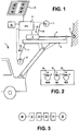
- reference numeral 1 indicates a drill rig for rock drilling, having an arm carrying a feed-beam 3.
- On the feed-beam 3 is, as conventionally, supported a to and fro movable rock drilling machine 2, which acts on a drill rod 4, which on its distal end is provided with a drill bit 5.
- the rock drilling machine 2 includes in a manner known per se a rotation device (not shown) for rotating the drill rod 4 during drilling.
- a rotation motor is hydraulically driven by a rotation fluid flow emanating from the pump 7 over the conduit 8.
- the pressure in the conduit 8 is the rotation pressure which is sensed by a pressure sensor 9.
- the rock drilling machine 2 is driven with a feed force F in its forward motion by a feed motor (not shown) being hydraulically driven by a feed flow which is generated by a pump 10 and transmitted over a feed conduit 11.
- the pressure in the feed conduit 11 is the feed pressure which is sensed by a pressure sensor 12.
- Reference numeral 6 indicates a central processing unit (CPU) which receives signal from the sensors 9 and 12 and thus monitors the pressures in these conduits.
- a percussion mechanism (not shown), inside the drilling machine housing is as usual driven by a percussion fluid flow having a percussion fluid pressure.
- the position and speed of the rock drill is determined with a length sensor (not shown) on the feed beam.
- FIG. 1 shows an underground rig but the invention can also be applied to a surface operated rig.
- 13 indicates an input device in the form of a touch screen, which is intended to communicate with the CPU in order to choose a mode that is to be used.
- six modes M1 - M6 are pre-programmed and represented with button fields on the touch screen.
- 14 indicates a memory which is connected to the CPU and which contains settings for the different modes. The memory can also be part of an internal memory in the CPU. Alternatively, values for a specific mode can be communicated to the rig over a LAN, over Internet or the like.
- Also other methods for performing entering modes can be used such as a menu in the operator program of the rig; that the rig is remote controlled for automatic entering of a mode that is to be used for a particular operating site; or that the rig over the CPU is simply connected to a set of buttons, one or more adjustment knobs etc.
- Fig. 2 an input device having a mode selector 30 for selecting one of three rock conditions, namely soft (S), medium (M) or hard (H) rock.
- S soft
- M medium
- H hard
- the device in Fig. 2 further has means for entering bit size by means of a rotation selector 31 for choosing between a suitable number of, preferably, standard bit sizes.
- a rotation selector 31 for choosing between a suitable number of, preferably, standard bit sizes.
- a suitable number of, preferably, standard bit sizes For example three (1, 2 and 3) representing 115, 125 and 140 mm in bit diameter.
- the device in Fig. 2 further has means for entering rod size.
- Reference numeral .32 indicates a rotation selector for selecting one of three (A, B and C) different rod sizes, here as an example representing 45, 51 and 60 mm in rod diameter.
- the input device in Fig. 2 could be modified, for example such that selectors for rod and bit size are included on a touch screen similar to the one in Fig. 1 .
- Fig. 3 is shown a method sequence in the form of a flow chart, wherein:
- the means related to the device according to the invention which executes the activated functions according to the invention are per se conventional control devices:
- the means for controlling the percussive mechanism can include a sensor for sensing damping pressure or feed pressure and as a response thereto control the percussion pressure and/or the stroke length of the percussive piston.
- the means for monitoring a parameter which is related to the rotation torque, for pressure or flow controlling the feed force as a response to variations of the value for that parameter is suitably on the one hand realized as software in the CPU in combination with per se known pressure control means, on the other hand realized as software in the CPU in combination with per se known fluid control means.
- the means for reducing and increasing, respectively, the feed force by altering a feed flow to a fluid motor means performing the feed in relation to a change of the parameter value is suitably realized as software in the CPU in combination with per se known fluid control means.
- the means for initiating an anti-jamming function with pre-set drilling machine parameters is suitably realized through the software in the CPU in combination with per se known mechanical setting means.
- a pressure compensated valve which means that a pressure difference over the inside and the outside of a main valve for feed shall be kept as constant as possible.
- pressure control can also be used an electronically controlled pressure limiter. When the pressure exceeds a certain level it is opened to tank and the pressure is reduced in the conduit.
- a controlled hydraulic pump can also be used.
- the anti-jam mechanism in respect of percussion drilling is based on the principle that the rotation torque level regulates the feed force level (or thrust force) in order to prevent the drill string from jamming. This is based on the theory that the torque level is proportional to the feed force supplied to the drill string. When too much feed force is applied at certain rock conditions, the torque level will elevated too high and beyond the capabilities of the rock drill rotation motor. Jamming conditions will then appear.
- the parameters in the anti-jam mechanism are pre-defined in such a way that virtually any drill operator easily can adjust the system in the direction of its optimum when the feed force is set by the system, much could be gained.
- the anti-jam process is as efficient as possible at any time in order to achieve smooth drilling and best use of energy.
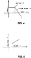
- feed force is represented as a function of torque level starting from T1: F - k(T - T1).
- T1 in the above equation is defined as a function of both bit size D and rock hardness H.
- the slope k of the curve is also a function of bit size D and rock hardness H.
- the basis for that evaluation can be examinations of the rock, the mountain, empirically obtained values during test drillings etc.
- Fig. 6 a display and input arrangement for representing different parameter values and for allowing manual adjustments.
- the input means for operator input to the system can be an override device which allows the operator, preferably within ranges, to amend a parameter value selected by the system.
- the system gives indications of recommended settings to the operator within recommended parameter ranges, whereby the operator is recommended to make adjustments within these ranges.
- Fig. 6 shows a display screen layout 33 having three parameter instruments: a rotation pressure instrument 34, a percussion pressure instrument 35 and a damping pressure instrument 36.
- the damping pressure instrument 36 can be exchanged for a feed (motor) pressure instrument 36. In that case, recommended range values for feed pressure can be provided. Like what is described above, the operator can undertake adjustments of the feed pressure settings according to the recommendations.
- each one of the instruments 35 and 36 in a semi manual mode, shows indications of recommended ranges, inside which, an operator is recommended to make adjustments.
- indicators 38.1, 38.2 and 38.3 are control level indicators indicating levels where different functions become active.
- the recommended range is indicated by a minimum limit indicator being indicated with 39.1 and a maximum limit indicator with 39.2.
- a minimum limit indicator being indicated with 39.1
- a maximum limit indicator with 39.2.
- the damping pressure is the result of feed pressure and rock hardness. Softer rock usually gives a lower damping pressure than harder rock with the same feed pressure. By increasing feed pressure, the damping pressure will increase.
- the recommended damping pressure range for the selected mode is shown in instrument 36, where a minimum limit indicator is indicated with 40.1, a maximum limit indicator with 40.2. 40.3 indicates a control level indicator corresponding to indicators 38.1, 38.2, 38.3 on instrument 34.
- ranges between the respective minimum limit indicator and maximum limit indicator are ranges, within which the operator is recommended to make adjustments.
- Input to the system can be made by a mouse-controlled cursor (not shown) pointing on up and down turned arrows adjacent to each instrument (not shown). Input could also be by pressing buttons on a separate keyboard (not shown).
- the screen can also be a touch screen for direct input of data.
- an input desired value is preferably indicated with a specific marker, e.g. similar to the indicators, in respect of a each instrument.
- the display screen layout in Fig. 6 could also indicate other parameter values in different fields (not shown here). These parameters are not subject to being influenced by the operator in this embodiment.
- a screen with the layout 33 can be the same as screen 33 in Fig. 1 or be in parallel with such a screen.
- parameters could also be entered into the system over a LAN or in any other suitable manner.
Landscapes
- Life Sciences & Earth Sciences (AREA)
- Engineering & Computer Science (AREA)
- Geology (AREA)
- Mining & Mineral Resources (AREA)
- Physics & Mathematics (AREA)
- Environmental & Geological Engineering (AREA)
- Fluid Mechanics (AREA)
- General Life Sciences & Earth Sciences (AREA)
- Geochemistry & Mineralogy (AREA)
- Earth Drilling (AREA)
- Percussive Tools And Related Accessories (AREA)
Claims (12)
- Procédé de commande d'une installation (1) de forage qui comprend un véhicule porteur doté d'au moins une poutre (3) d'avance, sur laquelle une machine (2) de forage peut être animée d'un mouvement de va et vient, des paramètres d'installation étant fixés par une unité (6) de commande et chaque mode parmi une pluralité de modes de fonctionnement (M1-M6) comprenant des réglages de fonctionnement spécifiés pour différents paramètres de fonctionnement de l'installation, chaque mode de fonctionnement (M1-M6) étant sélectionnable de telle façon que le fonctionnement de l'installation soit lié à un type particulier de roche dans laquelle le forage doit être effectué, et- chaque mode de fonctionnement (M1-M6) comprenant des réglages de fonctionnement qui sont adaptés au type de roche prédominant, caractérisé en ce que la taille du trépan est sélectionnée, et une ou plusieurs des grandeurs suivantes variant en fonction de la taille du trépan : débit de lavage, vitesse de rotation, pression d'avance, pression de percussion, relation de rapport force d'avance-couple de rotation, point de départ pour amorcer la fonction anti-coincement,- l'activation d'un mode de fonctionnement (M1-M6) activant, désactivant ou réglant également les valeurs de paramètres pour différentes fonctions de commande de forage, qui sont une ou plusieurs fonctions du groupe : surpression, lavage du trou, fonction de commande d'amortissement, rotation renforcée, fonction anti-coincement, régulation en pression de l'avance, régulation en débit de l'avance.
- Procédé selon la revendication 1, caractérisé en ce que lesdits paramètres de fonctionnement sont une pluralité de paramètres du groupe : pression du moteur d'avance, pression du moteur de rotation, vitesse de rotation, pression de percussion, débit de fluide de percussion, débit du moteur d'avance, débit du moteur de rotation, débit de fluide de lavage, niveau de régulation de pression d'amortissement.
- Procédé selon la revendication 1 ou 2, caractérisé en ce que l'activation d'un mode de fonctionnement (Ml-M6) règle des valeurs pour des fonctions de commande de forage de l'installation (1).
- Procédé selon l'une quelconque des revendications précédentes, caractérisé en ce que lesdits modes de fonctionnement (M1-M6) sont liés à un type quelconque du groupe : roche tendre, roche semi-dure, roche dure, roche meuble, roche abrasive, roche contenant un minerai.
- Procédé selon l'une quelconque des revendications précédentes, caractérisé en ce que la taille de la tige est sélectionnée.
- Dispositif de commande d'une installation (1) de forage, qui comprend un véhicule porteur doté d'au moins une poutre (3) d'avance, sur laquelle une machine (2) de forage peut être animée d'un mouvement de va et vient, une unité (6) de commande étant agencée pour régler des paramètres pour l'installation, et le dispositif comprenant un moyen (14) de mémoire servant à stocker une pluralité de modes de fonctionnement (M1-M6), chaque mode de fonctionnement (M1-M6) comprenant des réglages de fonctionnement spécifiés pour différents paramètres de fonctionnement de l'installation, chaque mode de fonctionnement (M1-M6) étant sélectionnable de telle façon que le fonctionnement de l'installation soit lié à un type particulier de roche dans laquelle le forage doit être effectué, et- chaque mode de fonctionnement (M1-M6) comprenant des réglages de fonctionnement qui sont adaptés au type de roche prédominant,caractérisé en ce que
le dispositif comprend un dispositif d'entrée servant à introduire des données liées à la taille du trépan qui est sélectionnable, et un moyen servant à faire varier une ou plusieurs des grandeurs suivantes en fonction de la taille du trépan : débit de lavage, vitesse de rotation, pression d'avance, pression de percussion, relation de rapport force d'avance-couple de rotation, point de départ pour amorcer la fonction anti-coincement,- l'activation d'un mode de fonctionnement (M1-M6) activant, désactivant ou réglant également les valeurs de paramètres pour différentes fonctions de commande de forage, qui sont une ou plusieurs fonctions du groupe : surpression, lavage du trou, fonction de commande d'amortissement, rotation renforcée, fonction anti-coincement, régulation en pression de l'avance, régulation en débit de l'avance. - Dispositif selon la revendication 6, caractérisé en ce que lesdits paramètres de fonctionnement sont une pluralité de paramètres du groupe : pression du moteur d'avance, pression du moteur de rotation, vitesse de rotation, pression de percussion, débit de fluide de percussion, débit du moteur d'avance, débit du moteur de rotation, débit de fluide de lavage, niveau de régulation de pression d'amortissement.
- Dispositif selon la revendication 6 ou 7, caractérisé en ce que lors de l'activation d'un mode de fonctionnement (M1-M6), il est fait en sorte de régler des valeurs pour des fonctions de commande de forage de l'installation.
- Dispositif selon la revendication 6, 7 ou 8, caractérisé en ce que lesdites fonctions de commande de forage sont une ou plusieurs fonctions du groupe : surpression, lavage du trou, régulation en pression de l'avance, régulation en débit de l'avance, fonction anti-coincement, fonction de commande d'amortissement, super rotation, régulation de vitesse d'avance de la pression de percussion.
- Dispositif selon l'une quelconque des revendications 6 à 9, caractérisé en ce qu'il comprend un dispositif d'entrée servant à sélectionner l'un quelconque des états de roche du groupe : roche tendre, roche semi-dure, roche dure, roche meuble, roche abrasive, roche contenant un minerai.
- Dispositif selon l'une quelconque des revendications 6 à 10, comprenant un dispositif d'entrée servant à introduire des données liées à la taille de la tige qui est sélectionnable, caractérisé par un moyen servant à faire varier une ou plusieurs des grandeurs suivantes en fonction de la taille de la tige : pression de percussion, pression du moteur d'avance.
- Installation de forage comprenant un dispositif selon l'une quelconque des revendications 6 à 11.
Applications Claiming Priority (1)
| Application Number | Priority Date | Filing Date | Title |
|---|---|---|---|
| PCT/US2007/014781 WO2009002306A1 (fr) | 2007-06-26 | 2007-06-26 | Procédé et dispositif de commande d'une installation de forage de roche |
Publications (3)
| Publication Number | Publication Date |
|---|---|
| EP2173959A1 EP2173959A1 (fr) | 2010-04-14 |
| EP2173959A4 EP2173959A4 (fr) | 2015-12-30 |
| EP2173959B1 true EP2173959B1 (fr) | 2018-11-28 |
Family
ID=40185911
Family Applications (1)
| Application Number | Title | Priority Date | Filing Date |
|---|---|---|---|
| EP07809887.8A Active EP2173959B1 (fr) | 2007-06-26 | 2007-06-26 | Procédé et dispositif de commande d'une installation de forage de roche |
Country Status (9)
| Country | Link |
|---|---|
| US (1) | US8464808B2 (fr) |
| EP (1) | EP2173959B1 (fr) |
| JP (1) | JP5789374B2 (fr) |
| CN (1) | CN101765694B (fr) |
| AU (1) | AU2007355629B2 (fr) |
| CA (1) | CA2692027C (fr) |
| ES (1) | ES2710440T3 (fr) |
| WO (1) | WO2009002306A1 (fr) |
| ZA (1) | ZA201000430B (fr) |
Families Citing this family (37)
| Publication number | Priority date | Publication date | Assignee | Title |
|---|---|---|---|---|
| WO2010149827A1 (fr) | 2009-06-26 | 2010-12-29 | Sandvik Mining And Construction Oy | Procédé de commande de forage de roche |
| US8261855B2 (en) | 2009-11-11 | 2012-09-11 | Flanders Electric, Ltd. | Methods and systems for drilling boreholes |
| FI124052B (fi) * | 2010-05-25 | 2014-02-28 | Sandvik Mining & Constr Oy | Kallionporauslaite, menetelmä sen siirtoajoon sekä nopeudensäädin |
| SE535585C2 (sv) | 2010-09-20 | 2012-10-02 | Spc Technology Ab | Förfarande och anordning för slagverkande sänkhålsborrning |
| US20120123614A1 (en) * | 2010-11-17 | 2012-05-17 | INRO Technologies Limited | Method and apparatus for virtualizing industrial vehicles to automate task execution in a physical environment |
| SE535757C2 (sv) * | 2011-04-05 | 2012-12-11 | Atlas Copco Rock Drills Ab | Anordning och förfarande för berg- och betongbearbetning |
| JP5940904B2 (ja) * | 2012-06-18 | 2016-06-29 | 古河ロックドリル株式会社 | さく孔機 |
| US9151117B2 (en) * | 2012-08-31 | 2015-10-06 | Caterpillar Global Mining Llc | Media pressure cavitation protection system for rock drills |
| US10131042B2 (en) | 2013-10-21 | 2018-11-20 | Milwaukee Electric Tool Corporation | Adapter for power tool devices |
| SE538090C2 (sv) * | 2014-02-18 | 2016-03-01 | Atlas Copco Rock Drills Ab | Bergborrmaskin och förfarande för bergborrning |
| US10603770B2 (en) | 2015-05-04 | 2020-03-31 | Milwaukee Electric Tool Corporation | Adaptive impact blow detection |
| CN110213676B (zh) | 2015-05-04 | 2022-08-19 | 米沃奇电动工具公司 | 电动工具和无线通信方法 |
| US10295990B2 (en) | 2015-05-18 | 2019-05-21 | Milwaukee Electric Tool Corporation | User interface for tool configuration and data capture |
| CN107921613B (zh) | 2015-06-02 | 2020-11-06 | 米沃奇电动工具公司 | 具有电子离合器的多速电动工具 |
| WO2016205404A1 (fr) | 2015-06-15 | 2016-12-22 | Milwaukee Electric Tool Corporation | Outil de sertissage hydraulique |
| US10380883B2 (en) | 2015-06-16 | 2019-08-13 | Milwaukee Electric Tool Corporation | Power tool profile sharing and permissions |
| US10345797B2 (en) | 2015-09-18 | 2019-07-09 | Milwaukee Electric Tool Corporation | Power tool operation recording and playback |
| US10385614B2 (en) * | 2015-09-30 | 2019-08-20 | Park Industries, Inc. | Percussive/rotating drill with blow-out, broken bit, and pressure loss detection systems |
| PL3369292T3 (pl) | 2015-10-30 | 2021-04-06 | Milwaukee Electric Tool Corporation | Zdalne sterowanie, konfiguracja i monitorowanie oświetlenia |
| US11424601B2 (en) | 2015-11-02 | 2022-08-23 | Milwaukee Electric Tool Corporation | Externally configurable worksite power distribution box |
| EP3202537B1 (fr) | 2015-12-17 | 2019-06-05 | Milwaukee Electric Tool Corporation | Système et procédé de configuration d'un outil électrique doté d'un mécanisme d'impact |
| JP7189018B2 (ja) | 2016-01-05 | 2022-12-13 | ミルウォーキー エレクトリック ツール コーポレーション | 動力工具のための振動低減システム及び方法 |
| EP3411204B1 (fr) | 2016-02-03 | 2021-07-28 | Milwaukee Electric Tool Corporation | Système et procédés pour configurer une scie alternative |
| TWM552413U (zh) | 2016-02-25 | 2017-12-01 | 米沃奇電子工具公司 | 包括輸出位置感測器之動力工具 |
| TWM555274U (zh) | 2016-06-06 | 2018-02-11 | 米沃奇電子工具公司 | 用以與動力工具裝置作連接的行動裝置 |
| US11622392B2 (en) | 2016-06-06 | 2023-04-04 | Milwaukee Electric Tool Corporation | System and method for establishing a wireless connection between power tool and mobile device |
| WO2019116331A1 (fr) * | 2017-12-15 | 2019-06-20 | Van Der Walt Jan Daniel | Test de perforatrice de roches |
| WO2019116330A1 (fr) * | 2017-12-15 | 2019-06-20 | Van Der Walt Jan Daniel | Capture de données |
| CN108222915A (zh) * | 2018-02-11 | 2018-06-29 | 北京新能正源环境科技有限公司 | 锚杆钻机的监控系统、方法及锚杆钻机 |
| CN108678764A (zh) * | 2018-05-08 | 2018-10-19 | 河北卓秋实业有限公司 | 一种掘进设备及利用该设备进行掘进的方法 |
| CN108643825A (zh) * | 2018-05-21 | 2018-10-12 | 中国水利水电第十工程局有限公司 | 一种具安全控制系统的液压凿岩钻机 |
| US11002075B1 (en) | 2018-07-31 | 2021-05-11 | J.H. Fletcher & Co. | Mine drilling system and related method |
| CN109339763A (zh) * | 2018-11-02 | 2019-02-15 | 湖南五新隧道智能装备股份有限公司 | 一种全自动凿岩机及其防卡杆控制方法及系统 |
| US11591897B2 (en) | 2019-07-20 | 2023-02-28 | Caterpillar Global Mining Equipment Llc | Anti-jam control system for mobile drilling machines |
| EP3825066A1 (fr) | 2019-11-21 | 2021-05-26 | Hilti Aktiengesellschaft | Procédé de fonctionnement d'une machine-outil guidée à la main et machine-outil guidée à la main |
| CN113216837B (zh) * | 2021-05-17 | 2022-01-14 | 河海大学 | 一种超临界流体钻爆一体化双臂凿岩台车及其操控方法 |
| CN115387777B (zh) * | 2022-08-09 | 2024-05-31 | 中煤科工集团西安研究院有限公司 | 一种基于煤岩感知的液压坑道钻机给进回转控制方法 |
Family Cites Families (24)
| Publication number | Priority date | Publication date | Assignee | Title |
|---|---|---|---|---|
| US4354233A (en) * | 1972-05-03 | 1982-10-12 | Zhukovsky Alexei A | Rotary drill automatic control system |
| SU647446A1 (ru) | 1976-05-14 | 1979-02-15 | Центральное Проектное Конструкторско-Технологическое Бюро Министерства Цветной Металлургии Казахской Сср | Перфоратор дл бурени горных пород |
| US4165789A (en) * | 1978-06-29 | 1979-08-28 | United States Steel Corporation | Drilling optimization searching and control apparatus |
| JPS5921886A (ja) * | 1982-07-27 | 1984-02-03 | ヤマトボ−リング株式会社 | 自動制御ボ−リング装置 |
| FI68293B (fi) * | 1982-11-30 | 1985-04-30 | Airam Ab Oy | Foerfarande i laonghaolbergborrning och borrstaongsystem |
| JPH0816430B2 (ja) | 1987-06-17 | 1996-02-21 | 東京電力株式会社 | 自動ボ−リング装置 |
| FR2663680B1 (fr) * | 1990-06-26 | 1992-09-11 | Eimco Secoma | Dispositif de controle d'effort d'ancrage pour glissiere de foration. |
| FI94663C (fi) * | 1994-02-28 | 1995-10-10 | Tamrock | Sovitelma kallionporauslaitteen ohjauslaitteistosta |
| JPH07293185A (ja) | 1994-04-27 | 1995-11-07 | Tokyo Riyuuki Seizo Kk | クローラドリルの制御装置及び制御方法 |
| FI104279B (fi) * | 1996-11-27 | 1999-12-15 | Tamrock Oy | Menetelmä ja sovitelma kallionporauksen syötön ohjaamiseksi |
| JPH10306676A (ja) * | 1997-04-30 | 1998-11-17 | Furukawa Co Ltd | 自動さく孔機 |
| JPH10311193A (ja) * | 1997-05-09 | 1998-11-24 | Furukawa Co Ltd | さく孔制御装置 |
| JP3488905B2 (ja) * | 1997-12-09 | 2004-01-19 | ヤマモトロックマシン株式会社 | 油圧式さく岩機の制御装置 |
| DE60006647T2 (de) * | 1999-01-13 | 2004-09-30 | Vermeer Mfg. Co., Pella | Automatisiertes bohrplanungsverfahren und vorrichtung zum horizontalen richtungsbohren |
| JP2000337074A (ja) * | 1999-05-27 | 2000-12-05 | Furukawa Co Ltd | 自動穿孔装置 |
| US6308790B1 (en) * | 1999-12-22 | 2001-10-30 | Smith International, Inc. | Drag bits with predictable inclination tendencies and behavior |
| FI115553B (fi) * | 2001-05-15 | 2005-05-31 | Sandvik Tamrock Oy | Järjestely porauksen ohjaukseen |
| FI115552B (fi) * | 2002-11-05 | 2005-05-31 | Sandvik Tamrock Oy | Järjestely kallioporauksen ohjaamiseksi |
| FI121393B (fi) * | 2003-04-11 | 2010-10-29 | Sandvik Mining & Constr Oy | Menetelmä ja järjestelmä porareikätiedon hallitsemiseksi |
| US7546884B2 (en) * | 2004-03-17 | 2009-06-16 | Schlumberger Technology Corporation | Method and apparatus and program storage device adapted for automatic drill string design based on wellbore geometry and trajectory requirements |
| CN101160449B (zh) * | 2005-02-25 | 2012-02-08 | 联邦科学和工业研究组织 | 用于控制挖掘装置的方法和系统 |
| FI123273B (fi) * | 2005-08-30 | 2013-01-31 | Sandvik Mining & Constr Oy | Käyttöliittymä kallionporauslaitteelle |
| FI119263B (fi) * | 2005-08-30 | 2008-09-15 | Sandvik Tamrock Oy | Adaptiivinen käyttöliittymä kallionporauslaitteelle |
| SE532483C2 (sv) * | 2007-04-11 | 2010-02-02 | Atlas Copco Rock Drills Ab | Metod, anordning och bergborrningsrigg för styrning av åtminstone en borrparameter |
-
2007
- 2007-06-26 AU AU2007355629A patent/AU2007355629B2/en active Active
- 2007-06-26 ES ES07809887T patent/ES2710440T3/es active Active
- 2007-06-26 CN CN200780053550.8A patent/CN101765694B/zh active Active
- 2007-06-26 CA CA2692027A patent/CA2692027C/fr active Active
- 2007-06-26 JP JP2010514709A patent/JP5789374B2/ja active Active
- 2007-06-26 EP EP07809887.8A patent/EP2173959B1/fr active Active
- 2007-06-26 US US12/452,224 patent/US8464808B2/en active Active
- 2007-06-26 WO PCT/US2007/014781 patent/WO2009002306A1/fr not_active Ceased
-
2010
- 2010-01-20 ZA ZA2010/00430A patent/ZA201000430B/en unknown
Non-Patent Citations (1)
| Title |
|---|
| None * |
Also Published As
| Publication number | Publication date |
|---|---|
| CN101765694A (zh) | 2010-06-30 |
| JP5789374B2 (ja) | 2015-10-07 |
| ZA201000430B (en) | 2011-03-30 |
| JP2010531402A (ja) | 2010-09-24 |
| CN101765694B (zh) | 2014-04-30 |
| EP2173959A4 (fr) | 2015-12-30 |
| CA2692027C (fr) | 2014-12-30 |
| AU2007355629A1 (en) | 2008-12-31 |
| CA2692027A1 (fr) | 2008-12-31 |
| AU2007355629B2 (en) | 2013-07-18 |
| WO2009002306A1 (fr) | 2008-12-31 |
| ES2710440T3 (es) | 2019-04-25 |
| US20100101862A1 (en) | 2010-04-29 |
| US8464808B2 (en) | 2013-06-18 |
| WO2009002306A8 (fr) | 2010-03-04 |
| EP2173959A1 (fr) | 2010-04-14 |
Similar Documents
| Publication | Publication Date | Title |
|---|---|---|
| EP2173959B1 (fr) | Procédé et dispositif de commande d'une installation de forage de roche | |
| CA2469179C (fr) | Procede et equipement de commande de fonctionnement d'un appareil de forage de roche | |
| EP1558836B1 (fr) | Dispositif pour commander le forage de roche | |
| EP1436486B1 (fr) | Procede et agencement de commande du forage par percussion, se basant sur le degre de contrainte determine a partir de la mesure du taux d'entrainement | |
| EP2446114B1 (fr) | Procédé et appareil de commande de forage de roche | |
| US7198117B2 (en) | Method and arrangement for controlling percussion rock drilling | |
| US6253860B1 (en) | Method and arrangement for controlling rock drilling | |
| JP2015166548A (ja) | 削岩リグ制御方法及び装置 | |
| US11448013B2 (en) | Method and apparatus for percussion drilling | |
| US6293359B1 (en) | Pressure control of a drilling apparatus | |
| WO2009123535A1 (fr) | Procédé et appareil pour ajuster et contrôler un paramètre | |
| JPH10311193A (ja) | さく孔制御装置 | |
| AU2002333928B2 (en) | Method and arrangement of controlling of percussive drilling based on the stress level determined from the measured feed rate | |
| CA2310893C (fr) | Dispositif de commande de la pression d'un appareil de forage | |
| CA2258316C (fr) | Procede et dispositif servant a commander la perforation d'un rocher | |
| AU2002333928A1 (en) | Method and arrangement of controlling of percussive drilling based on the stress level determined from the measured feed rate |
Legal Events
| Date | Code | Title | Description |
|---|---|---|---|
| PUAI | Public reference made under article 153(3) epc to a published international application that has entered the european phase |
Free format text: ORIGINAL CODE: 0009012 |
|
| 17P | Request for examination filed |
Effective date: 20100115 |
|
| AK | Designated contracting states |
Kind code of ref document: A1 Designated state(s): AT BE BG CH CY CZ DE DK EE ES FI FR GB GR HU IE IS IT LI LT LU LV MC MT NL PL PT RO SE SI SK TR |
|
| AX | Request for extension of the european patent |
Extension state: AL BA HR MK RS |
|
| DAX | Request for extension of the european patent (deleted) | ||
| RA4 | Supplementary search report drawn up and despatched (corrected) |
Effective date: 20151202 |
|
| RIC1 | Information provided on ipc code assigned before grant |
Ipc: E21B 44/02 20060101ALI20151126BHEP Ipc: E21B 6/00 20060101ALI20151126BHEP Ipc: E21B 7/02 20060101AFI20151126BHEP |
|
| STAA | Information on the status of an ep patent application or granted ep patent |
Free format text: STATUS: EXAMINATION IS IN PROGRESS |
|
| 17Q | First examination report despatched |
Effective date: 20180119 |
|
| RAP1 | Party data changed (applicant data changed or rights of an application transferred) |
Owner name: EPIROC ROCK DRILLS AKTIEBOLAG Owner name: EPIROC DRILLING SOLUTIONS LLC |
|
| GRAP | Despatch of communication of intention to grant a patent |
Free format text: ORIGINAL CODE: EPIDOSNIGR1 |
|
| STAA | Information on the status of an ep patent application or granted ep patent |
Free format text: STATUS: GRANT OF PATENT IS INTENDED |
|
| INTG | Intention to grant announced |
Effective date: 20180711 |
|
| GRAS | Grant fee paid |
Free format text: ORIGINAL CODE: EPIDOSNIGR3 |
|
| GRAA | (expected) grant |
Free format text: ORIGINAL CODE: 0009210 |
|
| STAA | Information on the status of an ep patent application or granted ep patent |
Free format text: STATUS: THE PATENT HAS BEEN GRANTED |
|
| AK | Designated contracting states |
Kind code of ref document: B1 Designated state(s): AT BE BG CH CY CZ DE DK EE ES FI FR GB GR HU IE IS IT LI LT LU LV MC MT NL PL PT RO SE SI SK TR |
|
| REG | Reference to a national code |
Ref country code: GB Ref legal event code: FG4D |
|
| REG | Reference to a national code |
Ref country code: CH Ref legal event code: EP |
|
| REG | Reference to a national code |
Ref country code: AT Ref legal event code: REF Ref document number: 1070453 Country of ref document: AT Kind code of ref document: T Effective date: 20181215 |
|
| REG | Reference to a national code |
Ref country code: DE Ref legal event code: R096 Ref document number: 602007056990 Country of ref document: DE |
|
| REG | Reference to a national code |
Ref country code: IE Ref legal event code: FG4D |
|
| REG | Reference to a national code |
Ref country code: SE Ref legal event code: TRGR |
|
| REG | Reference to a national code |
Ref country code: NL Ref legal event code: MP Effective date: 20181128 |
|
| REG | Reference to a national code |
Ref country code: LT Ref legal event code: MG4D |
|
| REG | Reference to a national code |
Ref country code: ES Ref legal event code: FG2A Ref document number: 2710440 Country of ref document: ES Kind code of ref document: T3 Effective date: 20190425 |
|
| PG25 | Lapsed in a contracting state [announced via postgrant information from national office to epo] |
Ref country code: LV Free format text: LAPSE BECAUSE OF FAILURE TO SUBMIT A TRANSLATION OF THE DESCRIPTION OR TO PAY THE FEE WITHIN THE PRESCRIBED TIME-LIMIT Effective date: 20181128 Ref country code: IS Free format text: LAPSE BECAUSE OF FAILURE TO SUBMIT A TRANSLATION OF THE DESCRIPTION OR TO PAY THE FEE WITHIN THE PRESCRIBED TIME-LIMIT Effective date: 20190328 Ref country code: BG Free format text: LAPSE BECAUSE OF FAILURE TO SUBMIT A TRANSLATION OF THE DESCRIPTION OR TO PAY THE FEE WITHIN THE PRESCRIBED TIME-LIMIT Effective date: 20190228 Ref country code: LT Free format text: LAPSE BECAUSE OF FAILURE TO SUBMIT A TRANSLATION OF THE DESCRIPTION OR TO PAY THE FEE WITHIN THE PRESCRIBED TIME-LIMIT Effective date: 20181128 |
|
| PG25 | Lapsed in a contracting state [announced via postgrant information from national office to epo] |
Ref country code: PT Free format text: LAPSE BECAUSE OF FAILURE TO SUBMIT A TRANSLATION OF THE DESCRIPTION OR TO PAY THE FEE WITHIN THE PRESCRIBED TIME-LIMIT Effective date: 20190328 Ref country code: GR Free format text: LAPSE BECAUSE OF FAILURE TO SUBMIT A TRANSLATION OF THE DESCRIPTION OR TO PAY THE FEE WITHIN THE PRESCRIBED TIME-LIMIT Effective date: 20190301 |
|
| PG25 | Lapsed in a contracting state [announced via postgrant information from national office to epo] |
Ref country code: NL Free format text: LAPSE BECAUSE OF FAILURE TO SUBMIT A TRANSLATION OF THE DESCRIPTION OR TO PAY THE FEE WITHIN THE PRESCRIBED TIME-LIMIT Effective date: 20181128 |
|
| PG25 | Lapsed in a contracting state [announced via postgrant information from national office to epo] |
Ref country code: DK Free format text: LAPSE BECAUSE OF FAILURE TO SUBMIT A TRANSLATION OF THE DESCRIPTION OR TO PAY THE FEE WITHIN THE PRESCRIBED TIME-LIMIT Effective date: 20181128 Ref country code: CZ Free format text: LAPSE BECAUSE OF FAILURE TO SUBMIT A TRANSLATION OF THE DESCRIPTION OR TO PAY THE FEE WITHIN THE PRESCRIBED TIME-LIMIT Effective date: 20181128 Ref country code: PL Free format text: LAPSE BECAUSE OF FAILURE TO SUBMIT A TRANSLATION OF THE DESCRIPTION OR TO PAY THE FEE WITHIN THE PRESCRIBED TIME-LIMIT Effective date: 20181128 |
|
| PGFP | Annual fee paid to national office [announced via postgrant information from national office to epo] |
Ref country code: PL Payment date: 20190606 Year of fee payment: 9 Ref country code: IT Payment date: 20190621 Year of fee payment: 13 |
|
| REG | Reference to a national code |
Ref country code: DE Ref legal event code: R097 Ref document number: 602007056990 Country of ref document: DE |
|
| PG25 | Lapsed in a contracting state [announced via postgrant information from national office to epo] |
Ref country code: RO Free format text: LAPSE BECAUSE OF FAILURE TO SUBMIT A TRANSLATION OF THE DESCRIPTION OR TO PAY THE FEE WITHIN THE PRESCRIBED TIME-LIMIT Effective date: 20181128 Ref country code: SK Free format text: LAPSE BECAUSE OF FAILURE TO SUBMIT A TRANSLATION OF THE DESCRIPTION OR TO PAY THE FEE WITHIN THE PRESCRIBED TIME-LIMIT Effective date: 20181128 Ref country code: EE Free format text: LAPSE BECAUSE OF FAILURE TO SUBMIT A TRANSLATION OF THE DESCRIPTION OR TO PAY THE FEE WITHIN THE PRESCRIBED TIME-LIMIT Effective date: 20181128 |
|
| PLBE | No opposition filed within time limit |
Free format text: ORIGINAL CODE: 0009261 |
|
| STAA | Information on the status of an ep patent application or granted ep patent |
Free format text: STATUS: NO OPPOSITION FILED WITHIN TIME LIMIT |
|
| PG25 | Lapsed in a contracting state [announced via postgrant information from national office to epo] |
Ref country code: SI Free format text: LAPSE BECAUSE OF FAILURE TO SUBMIT A TRANSLATION OF THE DESCRIPTION OR TO PAY THE FEE WITHIN THE PRESCRIBED TIME-LIMIT Effective date: 20181128 |
|
| PGFP | Annual fee paid to national office [announced via postgrant information from national office to epo] |
Ref country code: GB Payment date: 20190627 Year of fee payment: 13 Ref country code: ES Payment date: 20190701 Year of fee payment: 13 Ref country code: DE Payment date: 20190627 Year of fee payment: 13 Ref country code: AT Payment date: 20190603 Year of fee payment: 13 |
|
| 26N | No opposition filed |
Effective date: 20190829 |
|
| PG25 | Lapsed in a contracting state [announced via postgrant information from national office to epo] |
Ref country code: MC Free format text: LAPSE BECAUSE OF FAILURE TO SUBMIT A TRANSLATION OF THE DESCRIPTION OR TO PAY THE FEE WITHIN THE PRESCRIBED TIME-LIMIT Effective date: 20181128 |
|
| REG | Reference to a national code |
Ref country code: CH Ref legal event code: PL |
|
| REG | Reference to a national code |
Ref country code: BE Ref legal event code: MM Effective date: 20190630 |
|
| PG25 | Lapsed in a contracting state [announced via postgrant information from national office to epo] |
Ref country code: TR Free format text: LAPSE BECAUSE OF FAILURE TO SUBMIT A TRANSLATION OF THE DESCRIPTION OR TO PAY THE FEE WITHIN THE PRESCRIBED TIME-LIMIT Effective date: 20181128 |
|
| PG25 | Lapsed in a contracting state [announced via postgrant information from national office to epo] |
Ref country code: LI Free format text: LAPSE BECAUSE OF NON-PAYMENT OF DUE FEES Effective date: 20190630 Ref country code: CH Free format text: LAPSE BECAUSE OF NON-PAYMENT OF DUE FEES Effective date: 20190630 Ref country code: BE Free format text: LAPSE BECAUSE OF NON-PAYMENT OF DUE FEES Effective date: 20190630 Ref country code: LU Free format text: LAPSE BECAUSE OF NON-PAYMENT OF DUE FEES Effective date: 20190626 |
|
| REG | Reference to a national code |
Ref country code: DE Ref legal event code: R119 Ref document number: 602007056990 Country of ref document: DE |
|
| REG | Reference to a national code |
Ref country code: AT Ref legal event code: MM01 Ref document number: 1070453 Country of ref document: AT Kind code of ref document: T Effective date: 20200626 |
|
| GBPC | Gb: european patent ceased through non-payment of renewal fee |
Effective date: 20200626 |
|
| PG25 | Lapsed in a contracting state [announced via postgrant information from national office to epo] |
Ref country code: GB Free format text: LAPSE BECAUSE OF NON-PAYMENT OF DUE FEES Effective date: 20200626 Ref country code: IE Free format text: LAPSE BECAUSE OF NON-PAYMENT OF DUE FEES Effective date: 20200626 |
|
| PG25 | Lapsed in a contracting state [announced via postgrant information from national office to epo] |
Ref country code: CY Free format text: LAPSE BECAUSE OF FAILURE TO SUBMIT A TRANSLATION OF THE DESCRIPTION OR TO PAY THE FEE WITHIN THE PRESCRIBED TIME-LIMIT Effective date: 20181128 Ref country code: DE Free format text: LAPSE BECAUSE OF NON-PAYMENT OF DUE FEES Effective date: 20210101 Ref country code: AT Free format text: LAPSE BECAUSE OF NON-PAYMENT OF DUE FEES Effective date: 20200626 |
|
| PG25 | Lapsed in a contracting state [announced via postgrant information from national office to epo] |
Ref country code: HU Free format text: LAPSE BECAUSE OF FAILURE TO SUBMIT A TRANSLATION OF THE DESCRIPTION OR TO PAY THE FEE WITHIN THE PRESCRIBED TIME-LIMIT; INVALID AB INITIO Effective date: 20070626 Ref country code: MT Free format text: LAPSE BECAUSE OF FAILURE TO SUBMIT A TRANSLATION OF THE DESCRIPTION OR TO PAY THE FEE WITHIN THE PRESCRIBED TIME-LIMIT Effective date: 20181128 |
|
| PG25 | Lapsed in a contracting state [announced via postgrant information from national office to epo] |
Ref country code: IT Free format text: LAPSE BECAUSE OF NON-PAYMENT OF DUE FEES Effective date: 20200626 |
|
| REG | Reference to a national code |
Ref country code: ES Ref legal event code: FD2A Effective date: 20211105 |
|
| PG25 | Lapsed in a contracting state [announced via postgrant information from national office to epo] |
Ref country code: ES Free format text: LAPSE BECAUSE OF NON-PAYMENT OF DUE FEES Effective date: 20200627 |
|
| REG | Reference to a national code |
Ref country code: AT Ref legal event code: UEP Ref document number: 1070453 Country of ref document: AT Kind code of ref document: T Effective date: 20181128 |
|
| PGFP | Annual fee paid to national office [announced via postgrant information from national office to epo] |
Ref country code: FI Payment date: 20250520 Year of fee payment: 19 |
|
| PGFP | Annual fee paid to national office [announced via postgrant information from national office to epo] |
Ref country code: FR Payment date: 20250520 Year of fee payment: 19 |
|
| PGFP | Annual fee paid to national office [announced via postgrant information from national office to epo] |
Ref country code: SE Payment date: 20250520 Year of fee payment: 19 |