EP2174100B1 - Flow sensor with moveable magnet - Google Patents
Flow sensor with moveable magnet Download PDFInfo
- Publication number
- EP2174100B1 EP2174100B1 EP20080780832 EP08780832A EP2174100B1 EP 2174100 B1 EP2174100 B1 EP 2174100B1 EP 20080780832 EP20080780832 EP 20080780832 EP 08780832 A EP08780832 A EP 08780832A EP 2174100 B1 EP2174100 B1 EP 2174100B1
- Authority
- EP
- European Patent Office
- Prior art keywords
- magnet
- flow sensor
- chamber
- flow
- fluid
- Prior art date
- Legal status (The legal status is an assumption and is not a legal conclusion. Google has not performed a legal analysis and makes no representation as to the accuracy of the status listed.)
- Not-in-force
Links
Images

Classifications
-
- G—PHYSICS
- G01—MEASURING; TESTING
- G01F—MEASURING VOLUME, VOLUME FLOW, MASS FLOW OR LIQUID LEVEL; METERING BY VOLUME
- G01F1/00—Measuring the volume flow or mass flow of fluid or fluent solid material wherein the fluid passes through a meter in a continuous flow
- G01F1/05—Measuring the volume flow or mass flow of fluid or fluent solid material wherein the fluid passes through a meter in a continuous flow by using mechanical effects
- G01F1/20—Measuring the volume flow or mass flow of fluid or fluent solid material wherein the fluid passes through a meter in a continuous flow by using mechanical effects by detection of dynamic effects of the flow
- G01F1/22—Measuring the volume flow or mass flow of fluid or fluent solid material wherein the fluid passes through a meter in a continuous flow by using mechanical effects by detection of dynamic effects of the flow by variable-area meters, e.g. rotameters
- G01F1/24—Measuring the volume flow or mass flow of fluid or fluent solid material wherein the fluid passes through a meter in a continuous flow by using mechanical effects by detection of dynamic effects of the flow by variable-area meters, e.g. rotameters with magnetic or electric coupling to the indicating device
-
- G—PHYSICS
- G01—MEASURING; TESTING
- G01F—MEASURING VOLUME, VOLUME FLOW, MASS FLOW OR LIQUID LEVEL; METERING BY VOLUME
- G01F1/00—Measuring the volume flow or mass flow of fluid or fluent solid material wherein the fluid passes through a meter in a continuous flow
- G01F1/05—Measuring the volume flow or mass flow of fluid or fluent solid material wherein the fluid passes through a meter in a continuous flow by using mechanical effects
- G01F1/20—Measuring the volume flow or mass flow of fluid or fluent solid material wherein the fluid passes through a meter in a continuous flow by using mechanical effects by detection of dynamic effects of the flow
- G01F1/28—Measuring the volume flow or mass flow of fluid or fluent solid material wherein the fluid passes through a meter in a continuous flow by using mechanical effects by detection of dynamic effects of the flow by drag-force, e.g. vane type or impact flowmeter
Definitions
- the present application relates generally to a flow sensor for fluids and more particularly relates to a flow sensor adaptable for use with fluids of varying viscosities.
- Beverage dispensers generally combine measured ratios and/or amounts of various fluids so as to produce a desired beverage. These fluids generally can be described as micro-ingredients, macro-ingredients, and diluents. Micro-ingredients generally have high reconstitution ratios while macro-ingredients are added either at full strength or at low reconstitution ratios, typically in the range of about 1 to 1 to about 6 to 1 with respect to the diluent. Macro-ingredients have a wide range of viscosities, in the range of 1 to 10,000 centipoise. Macro-ingredients include fruit juices, concentrated extracts, dairy products, sugar syrup, high fructose corn syrup, and similar types of ingredients.
- a beverage dispenser may have a number of beverage pumps in communication with a number of flow sensors so as to provide feedback and to detect "no flow” events such as sold out packages or blocked lines.
- the flow sensors used with macro-ingredient pumps need to accommodate the wide range of viscosities described above.
- Known flow sensors typically work in a narrow range of viscosities.
- the flow sensor should be reliable, provide adequate feedback, and be easy to clean.
- US 2004/0045368 discloses an apparatus to determine the flow of a fluid, the apparatus comprising a magnetic sample movably arranged in a hollow body which can be acted upon with a working pressure of the fluid.
- the apparatus further comprises a position sensor and an electromagnet wherein the electromagnet is controlled based on information from the position sensor to hold the magnetic sample in a position and wherein the flow rate is determined based on the current required to keep the magnetic sample in the position.
- the present application thus describes a flow sensor for determining the flow rate of a fluid therethrough.
- the flow sensor includes a linear chamber for the fluid to flow therethrough, a moveable magnet positioned within the chamber, a permanent stationary magnet positioned about the chamber, and one or more sensors positioned about the chamber to determine the position of the moveable magnet therein.
- the chamber may include a number of support ribs therein to support the moveable magnet.
- the moveable magnet and the stationary magnet may have a natural repulsion.
- the fluid flowing in the chamber overcomes the natural repulsion based upon the flow rate therethrough.
- the moveable magnet and the stationary magnet may be permanent magnets.
- the sensors may be Hall effect sensors or other type of magnetic field strength sensor. The sensors may be positioned about the chamber to determine the position of the moveable magnet therein by detecting a magnetic field about the moveable magnet.
- the flow sensor further may include a number of stationary magnets of varying magnetic fields, with each of the stationary magnets accommodating a fluid of a given viscosity.
- the flow sensor further may include a sheath positioned on the stationary magnet. A number of sheaths may be used with each of the sheaths varying the magnetic field of the stationary magnet so as to accommodate a fluid of a given viscosity.
- the moveable magnet may include a ring magnet.
- the chamber may include an internal spike and the ring magnet may be positioned for movement thereon.
- the present application further describes a method of determining the flow rate of a fluid through a flow path.
- the method may include the steps of positioning a first magnet within the flow path, positioning a second magnet about the flow path, flowing the fluid through the flow path, detecting the magnetic field about the first magnet, and determining the flow rate based upon the detected magnetic field.
- the flow sensor further may include a number of second magnets of differing magnetic fields and the method may include selecting one of the second magnets based upon the viscosity of the fluid.
- the method further may include placing a steel sheath on the second magnet so as to vary the magnetic field of the second magnet.
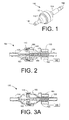
- Figs. 1-4 show an example of a flow sensor 100 as is described herein.
- the flow sensor 100 includes a chamber 110 with an inlet conduit 120 and an outlet conduit 130.
- the flow sensor chamber 110 may be made out of injection-molded plastics or similar types of substantially corrosion resistant materials.
- the chamber 110 may have an expanded diameter as compared to the inlet conduit 120 or the outlet conduit 130 for fluid flow therethrough.
- the chamber 110 may have a number of alignment ribs 140 positioned therein. Although any number or positioning of the ribs 140 may be used, four (4) ribs 140 positioned at about ninety degrees (90°) are shown.
- the chamber 110 also may have an integral stop 150 while the inlet 120 may have a tab 160 as will be described in more detail below.
- the chamber 110 preferably has a generally smooth inner geometry with large radii and few corners.
- the moveable magnet 170 Positioned within the chamber 110 and extending towards the inlet conduit 120 is a moveable magnet 170.
- the moveable magnet 170 may have a core of a permanent magnet material such as Neodymium-Iron-Boron (NdFeB), Ferrite, or similar types of permanent magnetic materials.
- the moveable magnet 170 also may have a plastic outer coating so as to be compatible with the fluids flowing thereabout.
- the moveable magnet 170 may be largely cylindrical and capsule-like in shape although any conventional shape may be used herein.
- the moveable magnet 170 may have a field strength of about 3000 to about 5000 Gauss although other ranges may be used.
- the moveable magnet 170 may be magnetized axially and in the direction of the fluid flow.
- a stationary ring magnet 180 Positioned around the chamber 110 may be a stationary ring magnet 180.
- the ring magnet 180 may encircle the chamber 110 in whole or in part.
- the stationary ring magnet 180 is shown positioned outside of the chamber 110 for ease of cleaning. Any location, however, may be used herein.
- the ring magnet 180 may be made out of Neodymium-Iron-Boron (NdFeB), Ferrite, or similar types of permanent magnetic materials.
- the ring magnet 180 may have a field strength of about 3000 to about 5000 Gauss although other ranges may be used.
- the moveable magnet 170 may be magnetized axially and in the direction of the fluid flow.
- the moveable magnet 170 and the stationary ring magnet 180 have a natural repulsion when in proximity to one another over the operational range of the moveable magnet 170 such that the repulsive forces increase as the moveable magnet 170 approaches the stationary ring magnet 180.
- the repulsion between the magnets 170, 180 creates a force in the opposite direction to that of the fluid flow coming through the inlet conduit 120.
- the magnitude of the repulsion force generally increases in a non-linear fashion as the fluid flow increases and the magnets 170, 180 move closer together.
- the moveable magnet 170 may maneuver between the integral stop 150 within the chamber 110 on one end and the tab 160 on the inlet conduit 120 on the other.
- the moveable magnet 170 may be supported within the chamber 110 via the alignment ribs 140.
- the magnets 170, 180, and the flow sensor 100 as a whole, may be used in any orientation.
- One or more detection sensors 190 may be positioned about the inlet 120.
- the detection sensors 190 may take the form of one or more Hall effect or other type of magnetic field-strength sensors.
- Other types of sensors 190 include magneto-restrictive sensors and similar types of devices.
- the detection sensors 190 detect the movement of the moveable magnet 170 within the chamber 110 as a change in the magnetic field in the vicinity of the moveable magnet 170 as described above. Signals from a number of individual sensors 190 may be averaged so as to minimize any noise in the measurement caused by vibration of the moveable magnet 170 or other interference.
- the detection sensors 190 determine the magnetic field therein and provide feedback to a pump control 195.
- the pump control 195 may be a conventional microprocessor or other type of control device.
- the pump control 195 may use a look up chart or other type of data structure to determine the flow rate based upon the detected magnetic field.
- fluid will flow through the flow sensor 100 through the inlet conduit 120, the chamber 110, and the outer conduit 130.
- the fluid may be water, a macro-ingredient, a micro-ingredient, and/or combinations thereof in liquid or gaseous form.
- the flow will overcome the repulsion between the moveable magnet 170 and the ring magnet 180. This force will move the moveable magnet 170 towards the ring magnet 180. An increase in the flow rate will move the moveable magnet 170 closer to the ring magnet 180.
- Fig. 3A shows the position of the moveable magnet 170 in a low flow situation while Fig. 3B shows the position of the moveable magnet 170 in a high flow situation.
- the change in the position of the moveable magnet 170 is detected by the detection sensors 190 based upon the strength of the magnetic field.
- the detection sensors 190 thus may provide magnetic field strength date to the pump control 195 as well as notification of no-flow events.
- the pump control 195 then may determine the flow rate therein and other flow rate conditions.
- the flow sensor 100 may be used over a wide range of viscosities. Changes in viscosity may be accommodated by changing the strength of the stationary ring magnet 180. A number of stationary rings 180 of varying magnetic field strength thus may be provided. Alternatively, a steel sheath 200 may be positioned about the ring magnet 180 as is shown in Fig. 5 . The steel sheath 220 reduces the magnetic field for use with water-like ingredients with viscosities close to about one (1) centipoise. Such water-like ingredients may not deflect the moveable magnet 170 an adequate distance so as to allow for flow detection when the moveable magnet 170 is opposed by a full strength magnetic field from the stationary ring magnet 180. The steel sheath 200 partially shorts the magnetic field so as reduce the magnetic field and the repulsive force on the moveable magnet 170 so as to accommodate the different viscosities.
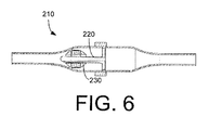
- Fig. 6 shows a further embodiment of a flow sensor 210.
- the flow sensor 210 is similar to the flow sensor 100 described above except that the alignment ribs 140 are not used. Instead, an internal spike 220 may be positioned within the chamber 110.
- a moveable magnet 230 in the form of a ring may be positioned on the spike. The moveable magnet 230 may maneuver about the spike 230 depending upon the flow conditions therethrough. Similar magnetic structures also may be used herein.
Landscapes
- Physics & Mathematics (AREA)
- Fluid Mechanics (AREA)
- General Physics & Mathematics (AREA)
- Measuring Volume Flow (AREA)
Applications Claiming Priority (2)
| Application Number | Priority Date | Filing Date | Title |
|---|---|---|---|
| US11/777,303 US7584657B2 (en) | 2007-07-13 | 2007-07-13 | Magnetic flow sensor |
| PCT/US2008/067214 WO2009012012A1 (en) | 2007-07-13 | 2008-06-17 | Flow sensor with moveable magnet |
Publications (2)
| Publication Number | Publication Date |
|---|---|
| EP2174100A1 EP2174100A1 (en) | 2010-04-14 |
| EP2174100B1 true EP2174100B1 (en) | 2015-05-06 |
Family
ID=39865184
Family Applications (1)
| Application Number | Title | Priority Date | Filing Date |
|---|---|---|---|
| EP20080780832 Not-in-force EP2174100B1 (en) | 2007-07-13 | 2008-06-17 | Flow sensor with moveable magnet |
Country Status (9)
| Country | Link |
|---|---|
| US (1) | US7584657B2 (pt) |
| EP (1) | EP2174100B1 (pt) |
| JP (1) | JP5183738B2 (pt) |
| CN (1) | CN101688797B (pt) |
| AU (1) | AU2008276392B2 (pt) |
| BR (1) | BRPI0813585A2 (pt) |
| RU (1) | RU2505787C2 (pt) |
| WO (1) | WO2009012012A1 (pt) |
| ZA (1) | ZA201000232B (pt) |
Families Citing this family (16)
| Publication number | Priority date | Publication date | Assignee | Title |
|---|---|---|---|---|
| EP2203378A2 (en) | 2007-09-06 | 2010-07-07 | The Coca-Cola Company | Systems and methods of selecting and dispensing mixed beverages |
| FR2944597B1 (fr) * | 2009-04-21 | 2011-05-13 | Airindex | Detecteur de debit de fluide ameliore |
| EP2485638B1 (en) * | 2009-10-07 | 2016-11-30 | Endophys Holdings, LLC | Pressure-sensing medical device |
| US8590562B2 (en) | 2010-12-17 | 2013-11-26 | Lincoln Industries Corporation | Fluid flow detection device |
| ITFI20120081A1 (it) * | 2012-04-20 | 2013-10-21 | Enrico Raddi | "flussostato magnetico e metodo per la rilevazione della presenza di flusso di liquido in un condotto" |
| WO2014003905A1 (en) | 2012-05-22 | 2014-01-03 | The Coca-Cola Company | Ingredient mixing module with a brushless motor for a beverage dispenser |
| WO2013176921A1 (en) | 2012-05-22 | 2013-11-28 | The Coca-Cola Company | Dispenser for beverages having a rotary micro-ingredient combination chamber |
| KR20160074203A (ko) * | 2014-12-18 | 2016-06-28 | 주식회사 엘지화학 | 점도 측정 장치 |
| US10028820B2 (en) | 2015-04-14 | 2018-07-24 | Cook Medical Technologies Llc | Carotid artery blood filter plugging alarm |
| CN105910659A (zh) * | 2015-12-17 | 2016-08-31 | 上海安钧电子科技有限公司 | 转板式磁力流量计 |
| US9664547B1 (en) * | 2016-01-05 | 2017-05-30 | Medtronic Xomed, Inc. | Flow management system |
| CN107907171B (zh) * | 2017-12-22 | 2024-04-16 | 中山市晶威电子科技有限公司 | 一种流量传感器 |
| CN109297548B (zh) * | 2018-09-29 | 2024-08-23 | 山东科尔自动化仪表股份有限公司 | 一种磁力流量计及测量方法 |
| CH718073A1 (fr) * | 2020-11-17 | 2022-05-31 | Droople Sa | Débitmètre et méthode de mesure de consommation d'eau. |
| CN114920199B (zh) * | 2021-12-30 | 2024-04-09 | 北京恒合信业技术股份有限公司 | 磁感式流量传感器 |
| CN117490782A (zh) * | 2023-12-29 | 2024-02-02 | 福建哈德仪表有限公司 | 一种可防磁干扰的涡轮流量计 |
Family Cites Families (28)
| Publication number | Priority date | Publication date | Assignee | Title |
|---|---|---|---|---|
| US2254698A (en) * | 1940-10-04 | 1941-09-02 | Gen Electric | Magnetic system |
| US3662598A (en) * | 1969-06-09 | 1972-05-16 | Jordan L Spencer | Flow control system |
| JPS559642B2 (pt) * | 1972-10-14 | 1980-03-11 | ||
| US4227409A (en) * | 1979-01-12 | 1980-10-14 | Milton Roy Company | Flowmeter |
| US4507976A (en) * | 1982-07-14 | 1985-04-02 | Morris Shamos | Flow meter with hall effect sensor and method |
| US4694161A (en) | 1985-11-04 | 1987-09-15 | Sackett Robert R | Fluid flow and level detector |
| US5079943A (en) | 1988-02-05 | 1992-01-14 | Cte Chem Tec Equipment Co. Inc. | Method of calibrating a volumetric fluid flow sensor |
| US4963857A (en) | 1989-06-26 | 1990-10-16 | Sackett Robert L | Translatable dual magnets |
| JPH0321772U (pt) * | 1989-07-13 | 1991-03-05 | ||
| US4953857A (en) * | 1989-07-27 | 1990-09-04 | Lemire Brett J | Orthopedic back support attachment for a weight lifter's bench |
| DE4027028C2 (de) * | 1990-08-27 | 1994-09-15 | Prominent Dosiertechnik Gmbh | Verfahren und Vorrichtung zur Bestimmung der Durchflußmenge eines Fluids mit einer pulsierenden Strömung |
| GB9027256D0 (en) * | 1990-12-17 | 1991-02-06 | Minnesota Mining & Mfg | Device |
| JP2929158B2 (ja) * | 1993-12-29 | 1999-08-03 | 東京計装株式会社 | 面積式流量計 |
| DE19616281C2 (de) * | 1995-04-26 | 2001-04-19 | Murray F Feller | Magnetischer Durchflußsensor |
| US5578763A (en) * | 1995-06-22 | 1996-11-26 | The Trustees Of Columbia University In The City Of New York | Electromagnetic flow meter |
| US5655568A (en) * | 1995-08-08 | 1997-08-12 | Bhargava; Raj | Passive flow regulating device |
| JPH09251029A (ja) * | 1996-03-14 | 1997-09-22 | Tokyo Rika Kogyosho:Kk | 流体検出装置 |
| RU2134405C1 (ru) * | 1997-02-10 | 1999-08-10 | Казанский государственный технический университет им.А.Н.Туполева | Расходомер-счетчик газа |
| JPH10288542A (ja) * | 1997-04-16 | 1998-10-27 | Somic Ishikawa:Kk | 流量検出装置 |
| US6619139B2 (en) * | 2001-02-16 | 2003-09-16 | Enginuity, Llc | Gas flow sensor and high pressure gaseous fuel injection system |
| ITMI20010632A1 (it) * | 2001-03-23 | 2002-09-23 | Pettinaroli Flii Spa | Misuratore ottico di portata |
| US6673051B2 (en) * | 2001-04-02 | 2004-01-06 | Hook Research Foundation | Magnetic valve bladder cycler drainage system and use method with urinary catheters |
| US6591694B2 (en) * | 2001-06-14 | 2003-07-15 | Taiwan Semiconductor Manufacturing Co., Ltd. | Flow meter with a self-illuminating floater |
| US6898984B2 (en) | 2002-08-16 | 2005-05-31 | Levitronix Llc | Measuring apparatus to determine the flow of a fluid |
| US6881507B2 (en) * | 2003-06-04 | 2005-04-19 | Milos Milacic | Method and apparatus for measuring the mass flow of hydrogen in a fuel cell |
| US7130750B1 (en) * | 2005-03-22 | 2006-10-31 | Racine Federated, Inc. | Flow meter with magnetoresistive sensors and method of measuring flow |
| DE102006008595A1 (de) * | 2006-02-24 | 2007-08-30 | Abb Patent Gmbh | Schwebekörper-Durchflussmesser |
| US7798783B2 (en) * | 2006-04-06 | 2010-09-21 | Micropump, Inc. | Magnetically driven valveless piston pumps |
-
2007
- 2007-07-13 US US11/777,303 patent/US7584657B2/en not_active Expired - Fee Related
-
2008
- 2008-06-17 WO PCT/US2008/067214 patent/WO2009012012A1/en not_active Ceased
- 2008-06-17 JP JP2010516112A patent/JP5183738B2/ja not_active Expired - Fee Related
- 2008-06-17 BR BRPI0813585-1A2A patent/BRPI0813585A2/pt not_active IP Right Cessation
- 2008-06-17 EP EP20080780832 patent/EP2174100B1/en not_active Not-in-force
- 2008-06-17 AU AU2008276392A patent/AU2008276392B2/en not_active Ceased
- 2008-06-17 CN CN2008800244507A patent/CN101688797B/zh not_active Expired - Fee Related
- 2008-06-17 RU RU2010103931/28A patent/RU2505787C2/ru active
-
2010
- 2010-01-12 ZA ZA201000232A patent/ZA201000232B/xx unknown
Also Published As
| Publication number | Publication date |
|---|---|
| ZA201000232B (en) | 2010-09-29 |
| US20090013797A1 (en) | 2009-01-15 |
| EP2174100A1 (en) | 2010-04-14 |
| JP2010533839A (ja) | 2010-10-28 |
| CN101688797B (zh) | 2013-05-29 |
| WO2009012012A1 (en) | 2009-01-22 |
| BRPI0813585A2 (pt) | 2014-12-30 |
| JP5183738B2 (ja) | 2013-04-17 |
| RU2010103931A (ru) | 2011-08-20 |
| CN101688797A (zh) | 2010-03-31 |
| AU2008276392B2 (en) | 2014-06-26 |
| HK1142671A1 (en) | 2010-12-10 |
| RU2505787C2 (ru) | 2014-01-27 |
| US7584657B2 (en) | 2009-09-08 |
| AU2008276392A1 (en) | 2009-01-22 |
Similar Documents
| Publication | Publication Date | Title |
|---|---|---|
| US7584657B2 (en) | Magnetic flow sensor | |
| US20130320116A1 (en) | Magnetic array for coupling fluid delivery components | |
| EP2694850B1 (en) | Electric valve device, in particular for a device for forming ice in a fridge | |
| EP2474014B1 (en) | Adjustable magnetic target | |
| US11448238B2 (en) | Pneumatic landfill pump cycle counter | |
| KR20150036526A (ko) | 직접 작용식 솔레노이드 작동기 | |
| US9765769B2 (en) | Sterile liquid pump with single use elements | |
| EP4097380B1 (en) | Rotary valve with encoder on rotor | |
| US10534012B2 (en) | Bidirectional flow switch | |
| CN111677899A (zh) | 带有流量检测功能的输送阀 | |
| WO2009127952A1 (en) | Volumetric flow measuring device for coffee machines | |
| HK1142671B (en) | Flow sensor with moveable magnet | |
| US10006794B2 (en) | Perpetual meter with noise damping | |
| EP3286467B1 (en) | A purge control system for discharging solids comprised in a fluid as well as a corresponding method | |
| US9989164B1 (en) | Air-operated, magnetic, non-stall air directional control valve | |
| EP3925928B1 (en) | Filling device for filling a receptacle | |
| KR101230502B1 (ko) | 혼합밸브 | |
| BRPI0813585B1 (pt) | Sensor de fluxo e método para determinar a vazão de um fluido | |
| EP3898496B1 (en) | A filling device for filling a receptacle and a filling machine | |
| US11124406B1 (en) | System and method for piston detection in a metering mechanism for use with beverage dispensing system | |
| CN107907171B (zh) | 一种流量传感器 | |
| KR20190116053A (ko) | 미생물 농축 소자 | |
| JP3201595B2 (ja) | 流量計 | |
| US20070243089A1 (en) | Check Valve for Displacement-Type Pump | |
| JP3201593B2 (ja) | 流量計 |
Legal Events
| Date | Code | Title | Description |
|---|---|---|---|
| PUAI | Public reference made under article 153(3) epc to a published international application that has entered the european phase |
Free format text: ORIGINAL CODE: 0009012 |
|
| 17P | Request for examination filed |
Effective date: 20100212 |
|
| AK | Designated contracting states |
Kind code of ref document: A1 Designated state(s): AT BE BG CH CY CZ DE DK EE ES FI FR GB GR HR HU IE IS IT LI LT LU LV MC MT NL NO PL PT RO SE SI SK TR |
|
| AX | Request for extension of the european patent |
Extension state: AL BA MK RS |
|
| DAX | Request for extension of the european patent (deleted) | ||
| 17Q | First examination report despatched |
Effective date: 20110810 |
|
| GRAP | Despatch of communication of intention to grant a patent |
Free format text: ORIGINAL CODE: EPIDOSNIGR1 |
|
| INTG | Intention to grant announced |
Effective date: 20141120 |
|
| GRAS | Grant fee paid |
Free format text: ORIGINAL CODE: EPIDOSNIGR3 |
|
| GRAA | (expected) grant |
Free format text: ORIGINAL CODE: 0009210 |
|
| AK | Designated contracting states |
Kind code of ref document: B1 Designated state(s): AT BE BG CH CY CZ DE DK EE ES FI FR GB GR HR HU IE IS IT LI LT LU LV MC MT NL NO PL PT RO SE SI SK TR |
|
| REG | Reference to a national code |
Ref country code: GB Ref legal event code: FG4D |
|
| REG | Reference to a national code |
Ref country code: CH Ref legal event code: EP |
|
| REG | Reference to a national code |
Ref country code: IE Ref legal event code: FG4D |
|
| REG | Reference to a national code |
Ref country code: AT Ref legal event code: REF Ref document number: 726029 Country of ref document: AT Kind code of ref document: T Effective date: 20150615 |
|
| REG | Reference to a national code |
Ref country code: DE Ref legal event code: R096 Ref document number: 602008038074 Country of ref document: DE Effective date: 20150618 |
|
| REG | Reference to a national code |
Ref country code: AT Ref legal event code: MK05 Ref document number: 726029 Country of ref document: AT Kind code of ref document: T Effective date: 20150506 |
|
| REG | Reference to a national code |
Ref country code: NL Ref legal event code: MP Effective date: 20150506 |
|
| REG | Reference to a national code |
Ref country code: LT Ref legal event code: MG4D |
|
| PG25 | Lapsed in a contracting state [announced via postgrant information from national office to epo] |
Ref country code: PT Free format text: LAPSE BECAUSE OF FAILURE TO SUBMIT A TRANSLATION OF THE DESCRIPTION OR TO PAY THE FEE WITHIN THE PRESCRIBED TIME-LIMIT Effective date: 20150907 Ref country code: LT Free format text: LAPSE BECAUSE OF FAILURE TO SUBMIT A TRANSLATION OF THE DESCRIPTION OR TO PAY THE FEE WITHIN THE PRESCRIBED TIME-LIMIT Effective date: 20150506 Ref country code: ES Free format text: LAPSE BECAUSE OF FAILURE TO SUBMIT A TRANSLATION OF THE DESCRIPTION OR TO PAY THE FEE WITHIN THE PRESCRIBED TIME-LIMIT Effective date: 20150506 Ref country code: FI Free format text: LAPSE BECAUSE OF FAILURE TO SUBMIT A TRANSLATION OF THE DESCRIPTION OR TO PAY THE FEE WITHIN THE PRESCRIBED TIME-LIMIT Effective date: 20150506 Ref country code: HR Free format text: LAPSE BECAUSE OF FAILURE TO SUBMIT A TRANSLATION OF THE DESCRIPTION OR TO PAY THE FEE WITHIN THE PRESCRIBED TIME-LIMIT Effective date: 20150506 Ref country code: NO Free format text: LAPSE BECAUSE OF FAILURE TO SUBMIT A TRANSLATION OF THE DESCRIPTION OR TO PAY THE FEE WITHIN THE PRESCRIBED TIME-LIMIT Effective date: 20150806 |
|
| PG25 | Lapsed in a contracting state [announced via postgrant information from national office to epo] |
Ref country code: BG Free format text: LAPSE BECAUSE OF FAILURE TO SUBMIT A TRANSLATION OF THE DESCRIPTION OR TO PAY THE FEE WITHIN THE PRESCRIBED TIME-LIMIT Effective date: 20150806 Ref country code: GR Free format text: LAPSE BECAUSE OF FAILURE TO SUBMIT A TRANSLATION OF THE DESCRIPTION OR TO PAY THE FEE WITHIN THE PRESCRIBED TIME-LIMIT Effective date: 20150807 Ref country code: LV Free format text: LAPSE BECAUSE OF FAILURE TO SUBMIT A TRANSLATION OF THE DESCRIPTION OR TO PAY THE FEE WITHIN THE PRESCRIBED TIME-LIMIT Effective date: 20150506 Ref country code: AT Free format text: LAPSE BECAUSE OF FAILURE TO SUBMIT A TRANSLATION OF THE DESCRIPTION OR TO PAY THE FEE WITHIN THE PRESCRIBED TIME-LIMIT Effective date: 20150506 Ref country code: IS Free format text: LAPSE BECAUSE OF FAILURE TO SUBMIT A TRANSLATION OF THE DESCRIPTION OR TO PAY THE FEE WITHIN THE PRESCRIBED TIME-LIMIT Effective date: 20150906 |
|
| PG25 | Lapsed in a contracting state [announced via postgrant information from national office to epo] |
Ref country code: IT Free format text: LAPSE BECAUSE OF FAILURE TO SUBMIT A TRANSLATION OF THE DESCRIPTION OR TO PAY THE FEE WITHIN THE PRESCRIBED TIME-LIMIT Effective date: 20150506 Ref country code: EE Free format text: LAPSE BECAUSE OF FAILURE TO SUBMIT A TRANSLATION OF THE DESCRIPTION OR TO PAY THE FEE WITHIN THE PRESCRIBED TIME-LIMIT Effective date: 20150506 Ref country code: DK Free format text: LAPSE BECAUSE OF FAILURE TO SUBMIT A TRANSLATION OF THE DESCRIPTION OR TO PAY THE FEE WITHIN THE PRESCRIBED TIME-LIMIT Effective date: 20150506 |
|
| REG | Reference to a national code |
Ref country code: CH Ref legal event code: PL |
|
| REG | Reference to a national code |
Ref country code: DE Ref legal event code: R097 Ref document number: 602008038074 Country of ref document: DE |
|
| PG25 | Lapsed in a contracting state [announced via postgrant information from national office to epo] |
Ref country code: MC Free format text: LAPSE BECAUSE OF FAILURE TO SUBMIT A TRANSLATION OF THE DESCRIPTION OR TO PAY THE FEE WITHIN THE PRESCRIBED TIME-LIMIT Effective date: 20150506 Ref country code: PL Free format text: LAPSE BECAUSE OF FAILURE TO SUBMIT A TRANSLATION OF THE DESCRIPTION OR TO PAY THE FEE WITHIN THE PRESCRIBED TIME-LIMIT Effective date: 20150506 Ref country code: SK Free format text: LAPSE BECAUSE OF FAILURE TO SUBMIT A TRANSLATION OF THE DESCRIPTION OR TO PAY THE FEE WITHIN THE PRESCRIBED TIME-LIMIT Effective date: 20150506 Ref country code: RO Free format text: LAPSE BECAUSE OF NON-PAYMENT OF DUE FEES Effective date: 20150506 Ref country code: CZ Free format text: LAPSE BECAUSE OF FAILURE TO SUBMIT A TRANSLATION OF THE DESCRIPTION OR TO PAY THE FEE WITHIN THE PRESCRIBED TIME-LIMIT Effective date: 20150506 |
|
| PLBE | No opposition filed within time limit |
Free format text: ORIGINAL CODE: 0009261 |
|
| STAA | Information on the status of an ep patent application or granted ep patent |
Free format text: STATUS: NO OPPOSITION FILED WITHIN TIME LIMIT |
|
| REG | Reference to a national code |
Ref country code: IE Ref legal event code: MM4A |
|
| 26N | No opposition filed |
Effective date: 20160209 |
|
| PG25 | Lapsed in a contracting state [announced via postgrant information from national office to epo] |
Ref country code: LI Free format text: LAPSE BECAUSE OF NON-PAYMENT OF DUE FEES Effective date: 20150630 Ref country code: IE Free format text: LAPSE BECAUSE OF NON-PAYMENT OF DUE FEES Effective date: 20150617 Ref country code: CH Free format text: LAPSE BECAUSE OF NON-PAYMENT OF DUE FEES Effective date: 20150630 |
|
| REG | Reference to a national code |
Ref country code: FR Ref legal event code: PLFP Year of fee payment: 9 |
|
| PG25 | Lapsed in a contracting state [announced via postgrant information from national office to epo] |
Ref country code: SI Free format text: LAPSE BECAUSE OF FAILURE TO SUBMIT A TRANSLATION OF THE DESCRIPTION OR TO PAY THE FEE WITHIN THE PRESCRIBED TIME-LIMIT Effective date: 20150506 |
|
| PG25 | Lapsed in a contracting state [announced via postgrant information from national office to epo] |
Ref country code: BE Free format text: LAPSE BECAUSE OF FAILURE TO SUBMIT A TRANSLATION OF THE DESCRIPTION OR TO PAY THE FEE WITHIN THE PRESCRIBED TIME-LIMIT Effective date: 20150506 |
|
| PG25 | Lapsed in a contracting state [announced via postgrant information from national office to epo] |
Ref country code: MT Free format text: LAPSE BECAUSE OF FAILURE TO SUBMIT A TRANSLATION OF THE DESCRIPTION OR TO PAY THE FEE WITHIN THE PRESCRIBED TIME-LIMIT Effective date: 20150506 |
|
| REG | Reference to a national code |
Ref country code: FR Ref legal event code: PLFP Year of fee payment: 10 |
|
| PG25 | Lapsed in a contracting state [announced via postgrant information from national office to epo] |
Ref country code: HU Free format text: LAPSE BECAUSE OF FAILURE TO SUBMIT A TRANSLATION OF THE DESCRIPTION OR TO PAY THE FEE WITHIN THE PRESCRIBED TIME-LIMIT; INVALID AB INITIO Effective date: 20080617 |
|
| PG25 | Lapsed in a contracting state [announced via postgrant information from national office to epo] |
Ref country code: SE Free format text: LAPSE BECAUSE OF FAILURE TO SUBMIT A TRANSLATION OF THE DESCRIPTION OR TO PAY THE FEE WITHIN THE PRESCRIBED TIME-LIMIT Effective date: 20150506 Ref country code: CY Free format text: LAPSE BECAUSE OF FAILURE TO SUBMIT A TRANSLATION OF THE DESCRIPTION OR TO PAY THE FEE WITHIN THE PRESCRIBED TIME-LIMIT Effective date: 20150506 Ref country code: NL Free format text: LAPSE BECAUSE OF FAILURE TO SUBMIT A TRANSLATION OF THE DESCRIPTION OR TO PAY THE FEE WITHIN THE PRESCRIBED TIME-LIMIT Effective date: 20150506 |
|
| PG25 | Lapsed in a contracting state [announced via postgrant information from national office to epo] |
Ref country code: TR Free format text: LAPSE BECAUSE OF FAILURE TO SUBMIT A TRANSLATION OF THE DESCRIPTION OR TO PAY THE FEE WITHIN THE PRESCRIBED TIME-LIMIT Effective date: 20150506 |
|
| PG25 | Lapsed in a contracting state [announced via postgrant information from national office to epo] |
Ref country code: LU Free format text: LAPSE BECAUSE OF NON-PAYMENT OF DUE FEES Effective date: 20150617 |
|
| REG | Reference to a national code |
Ref country code: FR Ref legal event code: PLFP Year of fee payment: 11 |
|
| REG | Reference to a national code |
Ref country code: DE Ref legal event code: R082 Ref document number: 602008038074 Country of ref document: DE |
|
| PGFP | Annual fee paid to national office [announced via postgrant information from national office to epo] |
Ref country code: FR Payment date: 20230523 Year of fee payment: 16 Ref country code: DE Payment date: 20230523 Year of fee payment: 16 |
|
| PGFP | Annual fee paid to national office [announced via postgrant information from national office to epo] |
Ref country code: GB Payment date: 20230523 Year of fee payment: 16 |
|
| REG | Reference to a national code |
Ref country code: DE Ref legal event code: R119 Ref document number: 602008038074 Country of ref document: DE |
|
| GBPC | Gb: european patent ceased through non-payment of renewal fee |
Effective date: 20240617 |
|
| PG25 | Lapsed in a contracting state [announced via postgrant information from national office to epo] |
Ref country code: DE Free format text: LAPSE BECAUSE OF NON-PAYMENT OF DUE FEES Effective date: 20250101 |
|
| PG25 | Lapsed in a contracting state [announced via postgrant information from national office to epo] |
Ref country code: FR Free format text: LAPSE BECAUSE OF NON-PAYMENT OF DUE FEES Effective date: 20240630 |
|
| PG25 | Lapsed in a contracting state [announced via postgrant information from national office to epo] |
Ref country code: GB Free format text: LAPSE BECAUSE OF NON-PAYMENT OF DUE FEES Effective date: 20240617 |