EP2174637A2 - Maschine zum Befüllen von Kapseln mit einem Produkt - Google Patents
Maschine zum Befüllen von Kapseln mit einem Produkt Download PDFInfo
- Publication number
- EP2174637A2 EP2174637A2 EP10152327A EP10152327A EP2174637A2 EP 2174637 A2 EP2174637 A2 EP 2174637A2 EP 10152327 A EP10152327 A EP 10152327A EP 10152327 A EP10152327 A EP 10152327A EP 2174637 A2 EP2174637 A2 EP 2174637A2
- Authority
- EP
- European Patent Office
- Prior art keywords
- machine
- cam
- piston
- product
- relative
- Prior art date
- Legal status (The legal status is an assumption and is not a legal conclusion. Google has not performed a legal analysis and makes no representation as to the accuracy of the status listed.)
- Granted
Links
- 239000002775 capsule Substances 0.000 title description 8
- 239000000825 pharmaceutical preparation Substances 0.000 description 10
- 229940127557 pharmaceutical product Drugs 0.000 description 10
- 238000012423 maintenance Methods 0.000 description 3
- 238000004140 cleaning Methods 0.000 description 2
- 241000237983 Trochidae Species 0.000 description 1
- 230000007797 corrosion Effects 0.000 description 1
- 238000005260 corrosion Methods 0.000 description 1
- 230000005484 gravity Effects 0.000 description 1
- 238000005507 spraying Methods 0.000 description 1
- 230000000087 stabilizing effect Effects 0.000 description 1
- 229910001220 stainless steel Inorganic materials 0.000 description 1
- 239000010935 stainless steel Substances 0.000 description 1
- 238000005406 washing Methods 0.000 description 1
- XLYOFNOQVPJJNP-UHFFFAOYSA-N water Substances O XLYOFNOQVPJJNP-UHFFFAOYSA-N 0.000 description 1
Images



Classifications
-
- A—HUMAN NECESSITIES
- A61—MEDICAL OR VETERINARY SCIENCE; HYGIENE
- A61J—CONTAINERS SPECIALLY ADAPTED FOR MEDICAL OR PHARMACEUTICAL PURPOSES; DEVICES OR METHODS SPECIALLY ADAPTED FOR BRINGING PHARMACEUTICAL PRODUCTS INTO PARTICULAR PHYSICAL OR ADMINISTERING FORMS; DEVICES FOR ADMINISTERING FOOD OR MEDICINES ORALLY; BABY COMFORTERS; DEVICES FOR RECEIVING SPITTLE
- A61J3/00—Devices or methods specially adapted for bringing pharmaceutical products into particular physical or administering forms
- A61J3/07—Devices or methods specially adapted for bringing pharmaceutical products into particular physical or administering forms into the form of capsules or similar small containers for oral use
- A61J3/071—Devices or methods specially adapted for bringing pharmaceutical products into particular physical or administering forms into the form of capsules or similar small containers for oral use into the form of telescopically engaged two-piece capsules
- A61J3/074—Filling capsules; Related operations
Definitions
- the present invention relates to a machine for filling containers with a product.
- the present invention relates to a machine for filling capsules with a powdered pharmaceutical product, to which the following description refers purely by way of example.
- a machine for filling capsules with a powdered pharmaceutical product comprising a conveying device, which is movable continuously along a given path and has a number of pockets, each for receiving a respective bottom shell of a relative capsule; a container containing the product; and a metering wheel mounted to rotate continuously about a respective longitudinal axis.
- the metering wheel has a number of metering devices, each of which is movable with the metering wheel along a portion of said path, in time with a relative bottom shell, to withdraw the product from said container and feed the product into the bottom shell, and comprises a cylinder and a piston moving vertically with respect to each other.
- the cylinder and piston are moved with respect to each other by respective actuating devices, each of which comprises at least one cam located over said container, and at least one tappet cooperating with the cam.
- the piston actuating device also comprises at least one spring fitted to the piston and interposed between the piston and the cylinder to keep the relative tappet normally in contact with the relative cam.
- the powdered pharmaceutical product scattered about the metering wheel must be stabilized to prevent it being inhaled by machine maintenance and cleaning personnel.
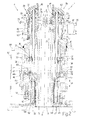
- Number 1 in Figures 1 and 2 indicates as a whole a machine for filling known capsules 2 with a powdered pharmaceutical product.
- Each capsule 2 comprises a substantially cup-shaped bottom shell 3, and a top shell (not shown) fitted to bottom shell 3.
- Machine 1 comprises a metering wheel 4, in turn comprising a tubular vertical upright 5, which has a longitudinal axis 6, extends upwards from a fixed frame 7 of machine 1, and is engaged by a shaft 8, which extends inside upright 5, coaxially with axis 6, and is connected in rotary manner to upright 5 to rotate continuously, with respect to upright 5 and under the control of a known actuating device 9, about axis 6.
- Shaft 8 supports a feed drum 10 comprising a substantially cylindrical casing 11, which is coaxial with axis 6, is positioned with its concavity facing downwards, is bounded laterally by a wall 12 extending about upright 5 and comprising a narrow top portion 13 and a wide bottom portion 14, and is closed at one end by an end wall 15, which is substantially perpendicular to axis 6 and fixed to one end of shaft 8 projecting outwards of upright 5.
- a sprocket 16 is formed on the outer surface of portion 13, is coaxial with axis 6, and forms part of a known conveying device 17 for feeding each bottom shell 3 along a given path P.
- Device 17 comprises a chain conveyor 18, which is looped about a number of sprockets (of which only sprocket 16 is shown in Figures 1 and 2 ) driven by device 9, and has a number of pockets 19, which are substantially cup-shaped with their concavity facing upwards, are equally spaced along conveyor 18, each receive a respective bottom shell 3 with its concavity facing upwards, and are fed continuously along path P by conveyor 18.
- Wheel 4 also comprises an annular container 20 containing the powdered pharmaceutical product, and which extends over sprocket 16 and is fitted in rotary manner to frame 7 to rotate continuously, with respect to frame 7 and under the control of a known actuating device not shown, about a respective longitudinal axis 21 parallel to axis 6, and at an angular speed substantially differing from the angular speed of drum 10 and, therefore, of sprocket 16.
- the powdered pharmaceutical product is fed into container 20 by a known hopper 22, which has a longitudinal axis 23 parallel to axes 6 and 21, is bounded at the bottom by an end wall 24 perpendicular to axis 23, houses a known mixing device 25 for mixing the pharmaceutical product, and has a feed conduit 26 extending downwards from hopper 22, projecting inside container 20, and fixed to hopper 22 at an opening 27 formed through wall 24 and parallel to axis 23.
- Drum 10 has a number of metering devices 28 equally spaced about axis 6 and fed continuously about axis 6 by drum 10. Each device 28 is conveyed by drum 10 in time with a relative pocket 19 along a portion of path P extending between a pickup station 29, where device 28 withdraws a given quantity of pharmaceutical product from container 20, and a filling station 30, where device 28 feeds the withdrawn pharmaceutical product into relative bottom shell 3.
- Each device 28 comprises a substantially cylindrical sleeve 31, which has a longitudinal axis 32 substantially parallel to axis 6, extends through portion 13 of drum 10, and is connected in axially-sliding manner to drum 10 to perform, with respect to drum 10 and under the control of an actuating device 33, straight movements in a direction 34 parallel to axes 6 and 32.
- Device 33 comprises a cam 35 common to sleeves 31 of all the metering devices 28; and a tappet roller 36 carried by sleeve 31 and engaging cam 35.
- Sleeve 31 is also connected in angularly-fixed manner to drum 10 by a tappet roller 37, which is carried by sleeve 31 and engages a relative slot 38, formed through portion 14 and parallel to direction 34, to prevent rotation of sleeve 31 about axis 32.
- a cylinder 39 is fixed to the top end of sleeve 31, has a longitudinal axis 40 substantially parallel to axes 32, and comprises a wide top portion 41 and a narrow bottom portion 42 connected to each other at a shoulder 43, which is perpendicular to axis 40 and through which is formed at least one opening 44.
- Device 28 also comprises a shaft 45, which is fitted inside sleeve 31, coaxially with axis 32, projects outwards of sleeve 31, and is connected in axially-sliding manner to sleeve 31 to perform, with respect to sleeve 31 and under the control of an actuating device 46, straight movements in direction 34.
- a shaft 45 which is fitted inside sleeve 31, coaxially with axis 32, projects outwards of sleeve 31, and is connected in axially-sliding manner to sleeve 31 to perform, with respect to sleeve 31 and under the control of an actuating device 46, straight movements in direction 34.
- Device 46 comprises a cam 47 common to shafts 45 of all the metering devices 28; and a tappet roller 48, which is fitted to shaft 45, is smaller in diameter than the width of cam 47 measured parallel to direction 34, and is maintained contacting a top wall of cam 47 by a pneumatic push device 49 for pushing shafts 45 upwards in direction 34.
- device 49 comprises a substantially cylindrical casing 50, which is coaxial with axis 6, is fixed, with its concavity facing upwards, to the bottom end of casing 11, and is bounded laterally by a wall 51 extending about upright 5.
- Casing 50 comprises a number of cavities 52, which are equal in number to metering devices 28, are equally spaced about axis 6 with the same spacing as devices 28, are formed in wall 51, parallel to direction 34, and are closed at the top by an annular flange 53 projecting radially inwards from the inner surface of drum 10 to define respective pneumatic chambers 54.
- Each chamber 54 is engaged in sliding manner by the bottom end of a relative shaft 45, and communicates pneumatically with a known compressed-air pneumatic device (not shown) by means of a relative pneumatic circuit 55.
- Circuit 55 comprises a radial conduit 56 formed through wall 51; an annular manifold 57 formed on the outer surface of upright 5, coaxially with axis 6, and connected in fluidtight manner to conduit 56 by two annular seals 58 fitted to the inner surface of wall 51, coaxially with axis 6; and an axial conduit 59 formed in drum 10, parallel to direction 34, and connected to said compressed-air pneumatic device (not shown) with the interposition of a solenoid valve 60.
- conduits 59 are equally spaced about axis 6, and each differ in length, measured parallel to direction 34, from the other conduits 59; and manifolds 57 are aligned with one another in direction 34; circuits 55 are completely independent of one another, and are connectable selectively to said compressed-air pneumatic device (not shown) by relative solenoid valves 60.
- Each shaft 45 is connected in angularly-fixed manner to drum 10 by a tappet roller 61 carried by shaft 45 and engaging relative slot 38 to prevent rotation of shaft 45 about axis 32.
- a substantially cylindrical piston 63 is fixed to the top end of shaft 45, projects downwards from bracket 62, engages relative cylinder 39 in sliding manner, and has a diameter approximately equal to but no larger than the diameter of narrow bottom portion 42 of cylinder 39.
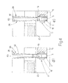
- cylinder 39 and piston 63 of metering device 28 considered are first lowered in direction 34 by respective cams 35 and 47 into contact with the top surface of the product inside container 20 ( Figure 4a ); piston 63 is then maintained contacting the top surface of the product by means of a further cam (not shown) projecting beneath cam 47 and engaged by a tappet roller 64 carried by shaft 45 ( Figures 4a and 4b ), while cylinder 39 is lowered into the product by cam 35 to define the correct amount of product to be withdrawn ( Figure 4b ); cylinder 39 and piston 63 are again lowered by respective cams 35 and 47 in time with each other, so as to move cylinder 39 into contact with container 20 ( Figure 4c ); and piston 63 is lowered further, to compact the product contained between cylinder 39 and piston 63 ( Figure 4c ), by a cam 65 projecting beneath can 47 and engaged by roller 64.
- piston 63 is lowered, to discharge the withdrawn product into relative bottom shell 3 ( Figure 4e ), by a cam 66 projecting beneath cam 47 and engaged by roller 64.
- Actuating devices 33 of sleeves 31, and actuating devices 46 of shafts 45 i.e. cams 35, 47, 65, 66, the cam (not shown) mounted at pickup station 29 to keep piston 63 in contact with the top surface of the product ( Figures 4a and 4b ), tappet rollers 36, 37, 48, 61, 64, and push device 49, are housed in a casing 67, which is fitted to frame 7 of machine 1, beneath container 20, is substantially parallelepiped-shaped, is bounded at the top by a wall 68 perpendicular to axis 6, and through which upright 5, shaft 8, and drum 10 project outwards of casing 67, and also houses solenoid valves 60 and said actuating device (not shown) of container 20.
- Actuating devices 33, 46 being housed inside casing 67, the powdered pharmaceutical product scattered about metering wheel 4 may therefore be stabilized easily at the end of each operating cycle of machine 1, thus permitting troublefree cleaning and maintenance of machine 1.
- Machine 1 also has the further advantage of pneumatic push device 49 enabling selective control of the operation of each metering device 28. More specifically, when a solenoid valve 60 disconnects pneumatic circuit 55 of relative metering device 28 from said compressed-air pneumatic device (not shown), relative piston 63 remains by force of gravity in a lowered position completely closing the narrow bottom portion 42 of relative cylinder 39.
- each metering device 28 can be prevented from withdrawing the product from container 20 when:
- solenoid valves 60 are eliminated, and chambers 54 are connected permanently to said compressed-air pneumatic device (not shown).
- the narrow bottom portion 42 of each cylinder 39 is closed, to prevent withdrawal of the product from container 20 in the aforementioned situations, by two deflecting cams, which are mounted at pickup station 29, and are inserted selectively along the paths of respective tappet rollers 36 and 48 in lieu of respective cams 35 and 47.
- the deflecting cams are designed to keep each piston 63 in the lowered position closing the narrow bottom portion 42 of relative cylinder 39, and, at pickup station 29, to move piston 63 and relative cylinder 39 over container 20 to prevent withdrawal of the product from container 20.
Landscapes
- Health & Medical Sciences (AREA)
- Chemical & Material Sciences (AREA)
- Medicinal Chemistry (AREA)
- Pharmacology & Pharmacy (AREA)
- Life Sciences & Earth Sciences (AREA)
- Animal Behavior & Ethology (AREA)
- General Health & Medical Sciences (AREA)
- Public Health (AREA)
- Veterinary Medicine (AREA)
- Basic Packing Technique (AREA)
Applications Claiming Priority (1)
| Application Number | Priority Date | Filing Date | Title |
|---|---|---|---|
| EP05425934A EP1803432B1 (de) | 2005-12-29 | 2005-12-29 | Vorrichtung zum Befüllen von Kapseln mit einem Produkt |
Related Parent Applications (1)
| Application Number | Title | Priority Date | Filing Date |
|---|---|---|---|
| EP05425934.6 Division | 2005-12-29 |
Publications (3)
| Publication Number | Publication Date |
|---|---|
| EP2174637A2 true EP2174637A2 (de) | 2010-04-14 |
| EP2174637A3 EP2174637A3 (de) | 2011-11-30 |
| EP2174637B1 EP2174637B1 (de) | 2013-02-13 |
Family
ID=36294957
Family Applications (2)
| Application Number | Title | Priority Date | Filing Date |
|---|---|---|---|
| EP10152327A Expired - Lifetime EP2174637B1 (de) | 2005-12-29 | 2005-12-29 | Maschine zum Befüllen von Kapseln mit einem Produkt |
| EP05425934A Expired - Lifetime EP1803432B1 (de) | 2005-12-29 | 2005-12-29 | Vorrichtung zum Befüllen von Kapseln mit einem Produkt |
Family Applications After (1)
| Application Number | Title | Priority Date | Filing Date |
|---|---|---|---|
| EP05425934A Expired - Lifetime EP1803432B1 (de) | 2005-12-29 | 2005-12-29 | Vorrichtung zum Befüllen von Kapseln mit einem Produkt |
Country Status (5)
| Country | Link |
|---|---|
| US (1) | US7640953B2 (de) |
| EP (2) | EP2174637B1 (de) |
| JP (1) | JP4885700B2 (de) |
| CN (1) | CN1994258A (de) |
| DE (1) | DE602005020334D1 (de) |
Families Citing this family (16)
| Publication number | Priority date | Publication date | Assignee | Title |
|---|---|---|---|---|
| DE102007031856A1 (de) * | 2007-07-09 | 2009-01-15 | Robert Bosch Gmbh | Vorrichtung zum Dosieren von pulverförmigem Füllgut |
| EP2090279B1 (de) * | 2008-02-18 | 2012-06-27 | MG2 S.r.l. | Maschine zum Füllen von Behältern mit mindestens einem Produkt |
| DE102008011733A1 (de) * | 2008-02-28 | 2009-09-03 | GM Global Technology Operations, Inc., Detroit | Kraftstoffbefüllvorrichtung |
| EP2100581A1 (de) * | 2008-03-12 | 2009-09-16 | MG2 S.r.l | Maschine zum Füllen von Behältern mit mindestens einem strombetriebenen Produkt |
| IT1394026B1 (it) * | 2009-05-11 | 2012-05-25 | Mg 2 Srl | Macchina per il riempimento di capsule con prodotti farmaceutici |
| US8359815B2 (en) * | 2009-05-11 | 2013-01-29 | Mg 2—S.R.L. | Machine for filling capsules with pharmaceutical products |
| IT1402461B1 (it) * | 2010-11-03 | 2013-09-13 | Mg 2 Srl | Metodo e macchina per il riempimento di capsule o simili con almeno due prodotti, in particolare prodotti farmaceutici in granuli |
| US9321881B2 (en) | 2011-08-12 | 2016-04-26 | Air Products And Chemicals, Inc. | Liquid methylenedianiline compositions |
| BR112015010601B1 (pt) * | 2012-11-09 | 2022-07-19 | Civitas Therapeutics, Inc. | Composição farmacêutica e uso da composição |
| ITBO20130178A1 (it) * | 2013-04-19 | 2014-10-20 | Mg 2 Srl | Macchina rotativa continua per il riempimento di capsule con prodotti farmaceutici |
| ES2602497T3 (es) * | 2014-08-14 | 2017-02-21 | Capsugel Belgium Nv | Aparato y proceso para verter materiales particulados |
| EP3015416B1 (de) * | 2014-10-31 | 2016-12-28 | Sidel Participations S.A.S. | Verteiler für eine Fülleinheit zum Befüllen von mehreren Artikeln mit einem fließfähigen Produkt |
| GB201620628D0 (en) * | 2016-12-05 | 2017-01-18 | 3P Innovation Ltd | Capsule Filler |
| CN112105331B (zh) * | 2018-01-31 | 2022-09-20 | 星德科技术有限公司 | 用于配量产品的装置 |
| CN108773824A (zh) * | 2018-09-17 | 2018-11-09 | 陈文静 | 一种用于饮用类食品包装的灌装机 |
| US20250170025A1 (en) * | 2022-01-19 | 2025-05-29 | Capsugel Belgium Nv | Device for dosing solid particulate material |
Family Cites Families (15)
| Publication number | Priority date | Publication date | Assignee | Title |
|---|---|---|---|---|
| DE1117471B (de) * | 1958-02-07 | 1961-11-16 | Hoefliger & Karg | Fuell- und Schliessmaschine fuer zweiteilige Kapseln |
| US3847191A (en) * | 1971-08-23 | 1974-11-12 | T Aronson | Means and methods for measuring and dispensing equal amounts of powdered material |
| US3893492A (en) * | 1973-08-06 | 1975-07-08 | John E Nohren | Apparatus and method for accurately dispensing and consolidating powdered material into receptacles |
| IT1033874B (it) * | 1975-04-07 | 1979-08-10 | Zanasi Nigris Spa | Procedimento e dispositivo per il dosaggio di prodotti pastosi piu o meno densi,da immettere in un qualsivoglia contenitore |
| IT1203137B (it) | 1978-11-09 | 1989-02-15 | Facchini Libero | Macchina opercolatrice a movimento continuo per il confezionamento di prodotti pulverulenti o granulari |
| IT1174815B (it) * | 1983-09-08 | 1987-07-01 | Mg 2 Spa | Macchina per il dosaggio di una quantita' prefissata di polvere all'interno di un contenitore |
| IT1245757B (it) * | 1991-01-15 | 1994-10-14 | Mg 2 Spa | Macchina per il dosaggio di prodotti farmaceutici in polvere. |
| US5111642A (en) * | 1991-01-23 | 1992-05-12 | Macofar S.P.A. | Machine for the dosage of powders in capsules, in particular for the pharmaceutical industry |
| ITBO940175A1 (it) * | 1994-04-22 | 1995-10-22 | Ima Spa | Dispositivo per la teleregolazione del volume di dosatori montati su una giostra, particolarmente per le macchine adibite al |
| IT1304780B1 (it) * | 1998-12-03 | 2001-03-29 | Ima Spa | Apparato per rilevare funzioni relative alla massa di tutte le dosi diprodotto da confezionare in capsule di gelatina dura, per rilevare |
| DE10001068C1 (de) * | 2000-01-13 | 2001-05-31 | Bosch Gmbh Robert | Vorrichtung zum Dosieren und Abgeben von Pulver in Hartgelatinekapseln oder dergleichen |
| GB0014082D0 (en) * | 2000-06-10 | 2000-08-02 | Glaxo Group Ltd | Method and apparatus for transferring a defined quantity of powder |
| GB0202912D0 (en) * | 2002-02-07 | 2002-03-27 | Meridica Ltd | Method and apparatus for introducing powder into a pocket |
| US7449342B2 (en) * | 2002-11-04 | 2008-11-11 | Transform Pharmaceuticals, Inc. | Methods of manipulating small amounts of solids |
| DE20313807U1 (de) * | 2003-09-03 | 2003-11-06 | Harro Höfliger Verpackungsmaschinen GmbH, 71573 Allmersbach | Vorrichtung zum Befüllen von Behältnissen, wie insbesondere von Hartgelatinekapseln |
-
2005
- 2005-12-29 DE DE602005020334T patent/DE602005020334D1/de not_active Expired - Lifetime
- 2005-12-29 EP EP10152327A patent/EP2174637B1/de not_active Expired - Lifetime
- 2005-12-29 EP EP05425934A patent/EP1803432B1/de not_active Expired - Lifetime
-
2006
- 2006-12-22 US US11/644,409 patent/US7640953B2/en not_active Expired - Fee Related
- 2006-12-25 JP JP2006347705A patent/JP4885700B2/ja not_active Expired - Fee Related
- 2006-12-26 CN CNA2006101682183A patent/CN1994258A/zh active Pending
Non-Patent Citations (1)
| Title |
|---|
| None |
Also Published As
| Publication number | Publication date |
|---|---|
| US7640953B2 (en) | 2010-01-05 |
| EP1803432A1 (de) | 2007-07-04 |
| US20070169839A1 (en) | 2007-07-26 |
| EP1803432B1 (de) | 2010-03-31 |
| EP2174637B1 (de) | 2013-02-13 |
| JP2007182260A (ja) | 2007-07-19 |
| JP4885700B2 (ja) | 2012-02-29 |
| CN1994258A (zh) | 2007-07-11 |
| DE602005020334D1 (de) | 2010-05-12 |
| EP2174637A3 (de) | 2011-11-30 |
Similar Documents
| Publication | Publication Date | Title |
|---|---|---|
| EP2090279B1 (de) | Maschine zum Füllen von Behältern mit mindestens einem Produkt | |
| EP1803432B1 (de) | Vorrichtung zum Befüllen von Kapseln mit einem Produkt | |
| JP5043504B2 (ja) | 容器を少なくとも1つの顆粒製品で充填するための機械 | |
| EP1982686B1 (de) | Vorrichtung und Verfahren zur Füllung von Kapseln | |
| CN102100638B (zh) | 用于对胶囊填充药剂的间歇式旋转机器 | |
| CN102100636A (zh) | 用于对胶囊填充药剂的间歇式旋转机器 | |
| US20090229705A1 (en) | Machine for filling containers with at least one powdered product | |
| CN102100639A (zh) | 用于对胶囊填充药剂的间歇式旋转机器 | |
| JP2012140181A (ja) | 少なくとも2つの製品、特に顆粒状の医薬製品をカプセルなどに充填する充填方法及び充填機 | |
| US5743069A (en) | Metering machine | |
| US7621390B2 (en) | Method and device for conveying articles on a machine for filling capsules with at least one pharmaceutical product | |
| US6585013B2 (en) | Machine for filling capsules with at least one product | |
| US6595249B2 (en) | Machine for filling capsules with a powdered product |
Legal Events
| Date | Code | Title | Description |
|---|---|---|---|
| PUAI | Public reference made under article 153(3) epc to a published international application that has entered the european phase |
Free format text: ORIGINAL CODE: 0009012 |
|
| AC | Divisional application: reference to earlier application |
Ref document number: 1803432 Country of ref document: EP Kind code of ref document: P |
|
| AK | Designated contracting states |
Kind code of ref document: A2 Designated state(s): DE IT |
|
| PUAL | Search report despatched |
Free format text: ORIGINAL CODE: 0009013 |
|
| RIC1 | Information provided on ipc code assigned before grant |
Ipc: A61J 3/07 20060101AFI20110930BHEP |
|
| AK | Designated contracting states |
Kind code of ref document: A3 Designated state(s): DE IT |
|
| RIC1 | Information provided on ipc code assigned before grant |
Ipc: A61J 3/07 20060101AFI20111024BHEP |
|
| 17P | Request for examination filed |
Effective date: 20120530 |
|
| GRAP | Despatch of communication of intention to grant a patent |
Free format text: ORIGINAL CODE: EPIDOSNIGR1 |
|
| GRAS | Grant fee paid |
Free format text: ORIGINAL CODE: EPIDOSNIGR3 |
|
| GRAA | (expected) grant |
Free format text: ORIGINAL CODE: 0009210 |
|
| AC | Divisional application: reference to earlier application |
Ref document number: 1803432 Country of ref document: EP Kind code of ref document: P |
|
| AK | Designated contracting states |
Kind code of ref document: B1 Designated state(s): DE IT |
|
| REG | Reference to a national code |
Ref country code: DE Ref legal event code: R096 Ref document number: 602005038179 Country of ref document: DE Effective date: 20130411 |
|
| PLBE | No opposition filed within time limit |
Free format text: ORIGINAL CODE: 0009261 |
|
| STAA | Information on the status of an ep patent application or granted ep patent |
Free format text: STATUS: NO OPPOSITION FILED WITHIN TIME LIMIT |
|
| 26N | No opposition filed |
Effective date: 20131114 |
|
| REG | Reference to a national code |
Ref country code: DE Ref legal event code: R097 Ref document number: 602005038179 Country of ref document: DE Effective date: 20131114 |
|
| REG | Reference to a national code |
Ref country code: DE Ref legal event code: R119 Ref document number: 602005038179 Country of ref document: DE |
|
| REG | Reference to a national code |
Ref country code: DE Ref legal event code: R119 Ref document number: 602005038179 Country of ref document: DE Effective date: 20140701 |
|
| PG25 | Lapsed in a contracting state [announced via postgrant information from national office to epo] |
Ref country code: DE Free format text: LAPSE BECAUSE OF NON-PAYMENT OF DUE FEES Effective date: 20140701 |
|
| PG25 | Lapsed in a contracting state [announced via postgrant information from national office to epo] |
Ref country code: IT Free format text: LAPSE BECAUSE OF NON-PAYMENT OF DUE FEES Effective date: 20130213 |
|
| PG25 | Lapsed in a contracting state [announced via postgrant information from national office to epo] |
Ref country code: IT Free format text: LAPSE BECAUSE OF NON-PAYMENT OF DUE FEES Effective date: 20131229 |