EP2174752B1 - Verriegelungsvorrichtung mit angelenkten Spannarmen, insbesondere zum Spannen von Werkstücken - Google Patents
Verriegelungsvorrichtung mit angelenkten Spannarmen, insbesondere zum Spannen von Werkstücken Download PDFInfo
- Publication number
- EP2174752B1 EP2174752B1 EP20090012624 EP09012624A EP2174752B1 EP 2174752 B1 EP2174752 B1 EP 2174752B1 EP 20090012624 EP20090012624 EP 20090012624 EP 09012624 A EP09012624 A EP 09012624A EP 2174752 B1 EP2174752 B1 EP 2174752B1
- Authority
- EP
- European Patent Office
- Prior art keywords
- arms
- pair
- main shaft
- arm
- shaft
- Prior art date
- Legal status (The legal status is an assumption and is not a legal conclusion. Google has not performed a legal analysis and makes no representation as to the accuracy of the status listed.)
- Not-in-force
Links
Images



Classifications
-
- B—PERFORMING OPERATIONS; TRANSPORTING
- B25—HAND TOOLS; PORTABLE POWER-DRIVEN TOOLS; MANIPULATORS
- B25B—TOOLS OR BENCH DEVICES NOT OTHERWISE PROVIDED FOR, FOR FASTENING, CONNECTING, DISENGAGING, OR HOLDING
- B25B5/00—Clamps
- B25B5/06—Arrangements for positively actuating jaws
- B25B5/12—Arrangements for positively actuating jaws using toggle links
- B25B5/122—Arrangements for positively actuating jaws using toggle links with fluid drive
Definitions
- the present invention refers to clamping devices with articulated levers, and provided with at least one swingably mounted clamping arm in order to allow at least one workpiece to be locked with respect to the body of the device, when the latter is fixed in a predetermined position.
- US-4 793 602 concerns such a clamping device provided with a pair of clamping arms swingably mounted about two parallel axes separate with respect to the body of the device.
- the two arms are susceptible to make a simultaneous and symmetrical movement between a back rest position and an advanced locking position with respect to the body, as a result of the sliding of a stem controlled by a pneumatic cylinder associated to the body of the device.
- the two arms are both connected to the same end of the stem through respective connecting rods, from opposite sides of the body of the device with respect to the stem.
- the clamping device of this document suffers from the drawback of not allowing an irreversible movement condition of the arms to be reached when the arms are in their advanced locking position, due to which both arms could move towards their back positions following to the application of a push to one of them tending to bring it in the back position, with the consequent release of the workpiece to be locked.
- this device is generally cumbersome and not very versatile, being inadequate for allowing the locking of workpieces positioned in different orientations when the body of the device is fixed in a predetermined position.
- the invention concerns a clamping device of the type mentioned in the preamble of the attached claim 1.
- Such a device is known from the Italian Patent application No. MI2002A001915 . It comprises a pair of arms swingably supported by the body of the device about respective parallel and separate axes, both axes being arranged on the same side of the body with respect to the stem that controls their movement. Each arm is associated to a corresponding toggle device, as a result of which the movement of the arms in their advanced position is irreversible. While one of the arms is connected to the control stem in such a way that its swinging movement is controlled directly by the sliding of the stem with respect to the body, the movement of the other arm is controlled by means of a linkage connected to the rotation axis of the first arm, the linkage being disposed outside the body of the device.
- EP-A-1 398 114 discloses a clamping device according to independent claim 1.
- one object of the invention is a device having the features defined in the attached claims.
- the device of the invention has a particularly compact structure which is therefore absolutely fit for operating in small spaces.
- the linkage that controls the movement of the secondary arm of the device is connected directly to the control stem and is arranged within the body, as a result of which there are not further movable elements protruding from the body other than the swingable arms. In this way, the linkage constituting the control mechanism of the secondary arm is effectively protected by the body of the device.
- the main shaft and the secondary shaft both have axial ends protruding from the body, which comprise shaped formations adapted to engage corresponding seats formed in the branches of said arms, in order to allow the arms to be mounted according to a plurality of different positions.
- the structure of the device allows the two swingable arms to be mounted according a plurality of different angular positions, in such a manner that it can be adapted to a plurality of locking configurations of different or differently oriented workpieces, also in the case the body of the device is fixed in the same position.
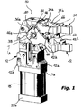
- a clamping device with articulated levers which can be used for locking workpieces, such as sheet metal elements, for example during welding operations, is designated 10 as a whole.
- the device 10 comprises a box-shaped body 12, which is defined by two shaped half-shells 12a and 12b coupled to one another.
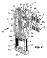
- a control stem 14 of the device 10 is axially slidably mounted between the two half-shells 12a and 12b, to the lower end 14a of which, with reference to the figures, a piston 16 of an actuator 18 is fixed, which is normally a pneumatic actuator, arranged below the body 12.
- the piston 16 is slidably and sealingly mounted in a chamber 20 extending between an upper head 21a connected to the half-shells 12a and 12b, and a bottom wall 21b, for actuating the stem 14 according to an alternating movement as a consequence of the feeding of a pressurized fluid from opposite sides of the piston 16 through feeding/discharge ducts 22a and 22b.
- the crank 30 is rigidly rotationally connected to a tubular main shaft 32 having axis A, whose axial ends protrude from opposite sides with respect to the body 12.
- a respective branch 34a, 34b of a first fork arm 34 of the device 10 is keyed.
- the axial ends of the tubular shaft 32 have a square cross-section and on the two branches 34a and 34b of the arm 34 respective coaxial seats of correspondingly square shape are formed, in order to allow the arm 34 to be positioned in one of a plurality of prefixed angular positions with respect to the shaft 32, as a result of the fixing by screws of respective removable clamping staples 36a and 36b.
- the assembly formed by the first pair of connecting rods 26 and by the crank 30 constitutes a toggle articulation of the first arm 34, whose function is to make the advanced operative position of the first arm 34 shown in figures 1 to 4 irreversible, in such a manner that the arm 34 cannot move from such position towards its back position in consequence of to a stress applied on it from the outside.
- a second shaft 38 extends coaxially to the axis A inside the tubular shaft 32, the axial ends of said second shaft protruding from opposite sides with respect to the ends of the shaft 32, for allowing the branches 42a and 42b of a second clamping arm 42 to be fixed.
- each of the branches 42a, 42b of the second arm 42 has a corresponding square seat 44 adapted to be engaged by a formation 40.
- the second arm 42 can be positioned according to one of a plurality of prefixed angular positions with respect to the shaft 38, following to the screw fixing of respective removable clamping staples 46a and 46b.
- a bracket 50 radially projecting from the shaft 38 and constituting a second crank of the device 10 is rotationally fixed, for example by means of a screw radial with respect to the axis A.
- the crank 50 has a transverse hole at its end opposite to the shaft 38, which is engaged by a pin 52 parallel to the axis A.
- the opposite ends of the pin 52 are rotatably inserted in a pair of holes of a second pair of connecting rods 54 each of which has a further hole for the engagement of a further pin 55 parallel to pin 52.
- the bracket 50 is conveniently formed in one piece with the shaft 38, for example by casting, in such a manner that the second crank of the device 10 consists of an appendage integral with the central portion of the shaft 38, that cantilevers radially with respect to axis A.
- the central part of the pin 55 is rotatably engaged in a first hole of a pair of generally S-shaped auxiliary rods 56, each of which has a second hole in which a respective end of a pin 60 is inserted which diametrically crosses the stem 14 in an intermediate portion thereof between the ends 14a and 14b.
- the assembly formed by the crank 50, by the second pair of connecting rods 54 and by the two auxiliary rods 56 constitutes a toggle articulation of the second arm 42, whose function is to make the advanced operative position of the second arm 42 shown in figures 1 to 4 irreversible, in such a way that the arm 42 in this position cannot move towards its back position as a result of stress applied on it from the outside.
- a counter element 62 is connected to the body 12, which is fixed through screws in a seat 64, and on which the branches 34a and 34b of the arm 34 and the branches 42a and 42b of the arm 42 rest from opposite sides, respectively, by means of adjustable supports constituted by screws 66.
- both arms 34 and 42 are in their advanced operative positions for clamping a workpiece (not shown).
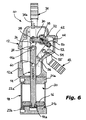
- the piston 16 moves towards the bottom wall 21b thus axially driving the stem 14 downwards.
- the sliding of the stem 14 causes, by means of the pair of auxiliary rods 56 and of the second pair of connecting rods 54, an angular movement of the second crank 50 and of the corresponding shaft 38, with the consequent rotation of the second clamping arm 42 that moves towards its back rest position.
- the corresponding toggle articulation constituted by the crank 50, by the pair of connecting rods 54 and by the two rods 56 must pass a "dead center position" that makes the advanced position of the arm 42 irreversible.
- both clamping arms 34 and 42 reach the respective rest positions shown in figures 5 and 6 .
- Figures 7 and 8 show the device 10 with the corresponding arms 34 and 42 mounted in another angular position, in their advanced or clamping positions and in their back or opening positions, respectively.
- the different mounting configuration is easily reached following to the removal of the clamping staples 36a and 36b of the arms 34a and 34b, and of the clamping staples 46a and 46b of the arms 42a and 42b, to the new positioning of the arms 34 and 42 with respect to the square ends of the shafts 32 and 38, and to the clamping of the staples 36a, 36b, 46a and 46b in the new position of the arms 34 and 42.
- the counter element 62 is fixed in the seat 68 formed in the body 12, by means of the fixing thereof through screws, in such a manner that it stands in a position interposed between the arms 34 and 42, so as to allow the arms 34 and 42 to rest on it from opposite sides in their new advanced operative position.
Landscapes
- Engineering & Computer Science (AREA)
- Mechanical Engineering (AREA)
- Jigs For Machine Tools (AREA)
- Manipulator (AREA)
Claims (11)
- Klemmvorrichtung mit Lenkhebeln, insbesondere zum Einspannen von Werkstücken, umfassend:- ein Gehäuse (12), in dem ein Schaft (14) axial gleitend gelagert ist, wobei die Gleitbewegung über Steuermittel (16, 18) erfolgt, die in dem Gehäuse (12) angeordnet sind,- eine Hauptwelle (32), die um eine Rotationsachse (A) drehbar ist, welche quer zu dem Schaft (14) verläuft und mit diesem über einen ersten Gelenkmechanismus (26, 30) verbunden ist,- einen ersten Klemmarm (34), der mit der Hauptwelle (32) verbunden ist und relativ zu dem Gehäuse (12) zwischen einer zurückgezogenen Ruhestellung und einer vorgerückten Arbeitsstellung schwenkbar ist,- einen zweiten Klemmarm (42), der in dem Gehäuse (12) angeordnet ist und simultan mit dem ersten Klemmarm (34) zwischen einer zurückgezogenen Ruhestellung und einer vorgerückten Arbeitsstellung schwenkbar ist, wobei die Schwenkbewegung über ein Kurbelgetriebe (50, 54, 56) gesteuert wird, das einen zweiten Gelenkmechanismus aufweist,
dadurch gekennzeichnet, dass der zweite Arm (42) mit einer Sekundärwelle (38) verbunden ist, die koaxial zu der Hauptwelle (32) drehbar ist derart, dass beide Arme (34, 42) um dieselbe Achse (A) schwenkbar sind. - Klemmvorrichtung nach Anspruch 1, dadurch gekennzeichnet, dass die Hauptwelle (32) rohrförmig ist und sich die Sekundärwelle (42) innerhalb dieser erstreckt.
- Klemmvorrichtung nach Anspruch 1, dadurch gekennzeichnet, dass mit der Hauptwelle (32) eine erste Kurbel (30) fest verbunden ist, die über ein Paar von Pleuelstangen (26) mit dem Steuerschaft (14) verbunden ist.
- Klemmvorrichtung nach einem der Ansprüche 1 bis 3, dadurch gekennzeichnet, dass das Kurbelgetriebe (50, 54, 56) direkt mit dem Steuerschaft (14) verbunden ist.
- Klemmvorrichtung nach Anspruch 4, dadurch gekennzeichnet, dass das gesamte Kurbelgetriebe (50, 54, 56) in dem Gehäuse (12) untergebracht ist.
- Klemmvorrichtung nach einem der vorhergehenden Ansprüche, dadurch gekennzeichnet, dass das Kurbelgetriebe (50, 54, 56) mit einer zweiten, auf der Sekundärwelle (38) befestigten Kurbel (50) verbunden ist und eine Paar von Pleuelstangen (54) sowie ein Paar von Hilfspleueln (56) aufweist, wobei das Paar der Pleuelstangen (54) an einem Ende mit der Kurbel (50) und am anderen Ende über Bolzen (52, 55) mit dem Paar der Hilfspleuel (56) verbunden ist, von denen ein Ende über einen weiteren Bolzen (60) mit dem Steuerschaft (14) verbunden ist.
- Klemmvorrichtung nach Anspruch 6, dadurch gekennzeichnet, dass die zweite Kurbel (50) integraler Bestandteil der Sekundärwelle (38) ist, von der sie von einem Mittelteil radial auskragend absteht.
- Klemmvorrichtung nach Anspruch 6 oder 7, dadurch gekennzeichnet, dass sowohl die Hauptwelle (32) als auch die Sekundärwelle (38) mit ihren axialen Enden aus dem Gehäuse (12) vorstehen und formschlüssig in entsprechende Sitze in Abschnitten (34a, 34b, 42a, 42b) der Arme (34, 42) eingreifen derart, dass diese in verschiedenen Positionen angebracht werden können.
- Klemmvorrichtung nach Anspruch 8, dadurch gekennzeichnet, dass die Formschlussverbindungen vierkantig sind.
- Klemmvorrichtung nach einem der vorhergehenden Ansprüche, dadurch gekennzeichnet, dass das Gehäuse (12) mehrere Sitze (64, 68) zur wahlweisen Fixierung eines Gegenelements (62) hat, an dem beide Arme (34, 42) in den vorgerückten Arbeitsstellungen zum Anschlag kommen.
- Klemmvorrichtung nach Anspruch 10, dadurch gekennzeichnet, dass zwischen jedem Abschnitt (34a, 34b, 42a, 42b) der Arme (34, 42) und dem Gegenelement (62) ein einstellbares Tragelement (66) eingesetzt ist.
Applications Claiming Priority (1)
| Application Number | Priority Date | Filing Date | Title |
|---|---|---|---|
| ITTO2008A000735A IT1391391B1 (it) | 2008-10-08 | 2008-10-08 | Dispositivo di chiusura a leve articolate, particolarmente per il bloccaggio di pezzi. |
Publications (2)
| Publication Number | Publication Date |
|---|---|
| EP2174752A1 EP2174752A1 (de) | 2010-04-14 |
| EP2174752B1 true EP2174752B1 (de) | 2014-04-02 |
Family
ID=40872335
Family Applications (1)
| Application Number | Title | Priority Date | Filing Date |
|---|---|---|---|
| EP20090012624 Not-in-force EP2174752B1 (de) | 2008-10-08 | 2009-10-06 | Verriegelungsvorrichtung mit angelenkten Spannarmen, insbesondere zum Spannen von Werkstücken |
Country Status (2)
| Country | Link |
|---|---|
| EP (1) | EP2174752B1 (de) |
| IT (1) | IT1391391B1 (de) |
Families Citing this family (2)
| Publication number | Priority date | Publication date | Assignee | Title |
|---|---|---|---|---|
| JP6119052B2 (ja) * | 2014-04-01 | 2017-04-26 | Smc株式会社 | クランプ装置 |
| CN110179288B (zh) * | 2019-05-13 | 2024-05-28 | 陈大伟 | 一种方便调节的多功能床护栏 |
Family Cites Families (6)
| Publication number | Priority date | Publication date | Assignee | Title |
|---|---|---|---|---|
| US4728137A (en) * | 1986-07-22 | 1988-03-01 | American Engineering And Trade, Inc. | Compound toggle robotic gripper |
| US4793602A (en) * | 1987-10-26 | 1988-12-27 | De-Sta-Co Division, Dover Resources, Inc. | Locking power clamp |
| CH692778A5 (de) * | 1997-05-07 | 2002-10-31 | Komax Holding Ag | Greifer. |
| US6290210B1 (en) * | 1999-06-01 | 2001-09-18 | Aladdin Engineering & Manufacturing | Clamping and lifting mechanism |
| US6412845B1 (en) * | 2000-07-07 | 2002-07-02 | Btm Corporation | Sealed gripper |
| DE10242058B4 (de) * | 2002-09-11 | 2006-01-05 | Nothelfer Gmbh | Kniehebelspannvorrichtung |
-
2008
- 2008-10-08 IT ITTO2008A000735A patent/IT1391391B1/it active
-
2009
- 2009-10-06 EP EP20090012624 patent/EP2174752B1/de not_active Not-in-force
Also Published As
| Publication number | Publication date |
|---|---|
| EP2174752A1 (de) | 2010-04-14 |
| ITTO20080735A1 (it) | 2010-04-09 |
| IT1391391B1 (it) | 2011-12-13 |
Similar Documents
| Publication | Publication Date | Title |
|---|---|---|
| CN110444417B (zh) | 双电源转换开关及其切换机构 | |
| EP2040887B1 (de) | Greifer mit mittlerem träger | |
| EP1830022B1 (de) | Gesteuerte Verschlussklemme | |
| US7155954B2 (en) | Pliers for crimping work pieces | |
| KR20080089660A (ko) | 유압 구동식 프레스 장치 및 설비물의 프레스 방법 | |
| EP2174752B1 (de) | Verriegelungsvorrichtung mit angelenkten Spannarmen, insbesondere zum Spannen von Werkstücken | |
| CN101855036A (zh) | 用于斜切锯的斜切锁定组件 | |
| US20120260491A1 (en) | Setting device, supply module for the setting device, and a joining method for connecting at least two components | |
| JP6434638B2 (ja) | 枢動可能アームの精密位置決めのための関節式レバー又はカム型作動装置 | |
| MX2012004942A (es) | Dispositivo de sujecion. | |
| CN102666023B (zh) | 夹紧设备 | |
| TWI290109B (en) | Actuator unit for a hydraulic brake | |
| CN102883835A (zh) | 旋锻机的工具单元 | |
| EP1524080B1 (de) | Verriegelungsvorrichtung mit einem Gelenkhebel zum Spannen von Werkstücken | |
| EP2241402B1 (de) | Vorrichtung zum Verriegeln von Werkstücken | |
| EP3078453B1 (de) | Betätigungsvorrichtung vom gelenkhebel- oder nockentyp zur genauen positionierung eines schwenkbaren arms | |
| EP2177319B1 (de) | Vorrichtung zum Stoppen der Oszillation des Arms eines Handhabungsgeräts mit schwenkbarem Hebel | |
| EP3587094B1 (de) | Formstempel für eine kartonherstellungsmaschine | |
| US4208901A (en) | Rivet tongs | |
| EP3296035B1 (de) | Crimpvorrichtung zum anpressen von rohrverbindungen auf flexiblen rohren | |
| JP4672393B2 (ja) | 皿取り加工装置 | |
| ITMO20130276A1 (it) | Braccio portautensili per macchine smontagomme | |
| SK500022011A3 (sk) | Method for bending pipes and similar products and device for making the same | |
| US11361919B2 (en) | Switch device with at least one electric switch element and a camshaft | |
| TW200916225A (en) | Device for automatically adjusting control cams in a forging machine |
Legal Events
| Date | Code | Title | Description |
|---|---|---|---|
| PUAI | Public reference made under article 153(3) epc to a published international application that has entered the european phase |
Free format text: ORIGINAL CODE: 0009012 |
|
| AK | Designated contracting states |
Kind code of ref document: A1 Designated state(s): AT BE BG CH CY CZ DE DK EE ES FI FR GB GR HR HU IE IS IT LI LT LU LV MC MK MT NL NO PL PT RO SE SI SK SM TR |
|
| AX | Request for extension of the european patent |
Extension state: AL BA RS |
|
| 17P | Request for examination filed |
Effective date: 20101006 |
|
| GRAP | Despatch of communication of intention to grant a patent |
Free format text: ORIGINAL CODE: EPIDOSNIGR1 |
|
| INTG | Intention to grant announced |
Effective date: 20130618 |
|
| GRAS | Grant fee paid |
Free format text: ORIGINAL CODE: EPIDOSNIGR3 |
|
| GRAA | (expected) grant |
Free format text: ORIGINAL CODE: 0009210 |
|
| AK | Designated contracting states |
Kind code of ref document: B1 Designated state(s): AT BE BG CH CY CZ DE DK EE ES FI FR GB GR HR HU IE IS IT LI LT LU LV MC MK MT NL NO PL PT RO SE SI SK SM TR |
|
| REG | Reference to a national code |
Ref country code: GB Ref legal event code: FG4D |
|
| REG | Reference to a national code |
Ref country code: AT Ref legal event code: REF Ref document number: 659792 Country of ref document: AT Kind code of ref document: T Effective date: 20140415 Ref country code: CH Ref legal event code: EP |
|
| REG | Reference to a national code |
Ref country code: IE Ref legal event code: FG4D |
|
| REG | Reference to a national code |
Ref country code: DE Ref legal event code: R096 Ref document number: 602009022880 Country of ref document: DE Effective date: 20140515 |
|
| REG | Reference to a national code |
Ref country code: AT Ref legal event code: MK05 Ref document number: 659792 Country of ref document: AT Kind code of ref document: T Effective date: 20140402 |
|
| REG | Reference to a national code |
Ref country code: NL Ref legal event code: VDEP Effective date: 20140402 |
|
| REG | Reference to a national code |
Ref country code: LT Ref legal event code: MG4D |
|
| PG25 | Lapsed in a contracting state [announced via postgrant information from national office to epo] |
Ref country code: LT Free format text: LAPSE BECAUSE OF FAILURE TO SUBMIT A TRANSLATION OF THE DESCRIPTION OR TO PAY THE FEE WITHIN THE PRESCRIBED TIME-LIMIT Effective date: 20140402 Ref country code: NO Free format text: LAPSE BECAUSE OF FAILURE TO SUBMIT A TRANSLATION OF THE DESCRIPTION OR TO PAY THE FEE WITHIN THE PRESCRIBED TIME-LIMIT Effective date: 20140702 Ref country code: CY Free format text: LAPSE BECAUSE OF FAILURE TO SUBMIT A TRANSLATION OF THE DESCRIPTION OR TO PAY THE FEE WITHIN THE PRESCRIBED TIME-LIMIT Effective date: 20140402 Ref country code: GR Free format text: LAPSE BECAUSE OF FAILURE TO SUBMIT A TRANSLATION OF THE DESCRIPTION OR TO PAY THE FEE WITHIN THE PRESCRIBED TIME-LIMIT Effective date: 20140703 Ref country code: CZ Free format text: LAPSE BECAUSE OF FAILURE TO SUBMIT A TRANSLATION OF THE DESCRIPTION OR TO PAY THE FEE WITHIN THE PRESCRIBED TIME-LIMIT Effective date: 20140402 Ref country code: NL Free format text: LAPSE BECAUSE OF FAILURE TO SUBMIT A TRANSLATION OF THE DESCRIPTION OR TO PAY THE FEE WITHIN THE PRESCRIBED TIME-LIMIT Effective date: 20140402 Ref country code: FI Free format text: LAPSE BECAUSE OF FAILURE TO SUBMIT A TRANSLATION OF THE DESCRIPTION OR TO PAY THE FEE WITHIN THE PRESCRIBED TIME-LIMIT Effective date: 20140402 Ref country code: BG Free format text: LAPSE BECAUSE OF FAILURE TO SUBMIT A TRANSLATION OF THE DESCRIPTION OR TO PAY THE FEE WITHIN THE PRESCRIBED TIME-LIMIT Effective date: 20140702 Ref country code: IS Free format text: LAPSE BECAUSE OF FAILURE TO SUBMIT A TRANSLATION OF THE DESCRIPTION OR TO PAY THE FEE WITHIN THE PRESCRIBED TIME-LIMIT Effective date: 20140802 |
|
| PG25 | Lapsed in a contracting state [announced via postgrant information from national office to epo] |
Ref country code: PL Free format text: LAPSE BECAUSE OF FAILURE TO SUBMIT A TRANSLATION OF THE DESCRIPTION OR TO PAY THE FEE WITHIN THE PRESCRIBED TIME-LIMIT Effective date: 20140402 Ref country code: SE Free format text: LAPSE BECAUSE OF FAILURE TO SUBMIT A TRANSLATION OF THE DESCRIPTION OR TO PAY THE FEE WITHIN THE PRESCRIBED TIME-LIMIT Effective date: 20140402 Ref country code: ES Free format text: LAPSE BECAUSE OF FAILURE TO SUBMIT A TRANSLATION OF THE DESCRIPTION OR TO PAY THE FEE WITHIN THE PRESCRIBED TIME-LIMIT Effective date: 20140402 Ref country code: LV Free format text: LAPSE BECAUSE OF FAILURE TO SUBMIT A TRANSLATION OF THE DESCRIPTION OR TO PAY THE FEE WITHIN THE PRESCRIBED TIME-LIMIT Effective date: 20140402 Ref country code: HR Free format text: LAPSE BECAUSE OF FAILURE TO SUBMIT A TRANSLATION OF THE DESCRIPTION OR TO PAY THE FEE WITHIN THE PRESCRIBED TIME-LIMIT Effective date: 20140402 Ref country code: AT Free format text: LAPSE BECAUSE OF FAILURE TO SUBMIT A TRANSLATION OF THE DESCRIPTION OR TO PAY THE FEE WITHIN THE PRESCRIBED TIME-LIMIT Effective date: 20140402 |
|
| PG25 | Lapsed in a contracting state [announced via postgrant information from national office to epo] |
Ref country code: PT Free format text: LAPSE BECAUSE OF FAILURE TO SUBMIT A TRANSLATION OF THE DESCRIPTION OR TO PAY THE FEE WITHIN THE PRESCRIBED TIME-LIMIT Effective date: 20140804 |
|
| REG | Reference to a national code |
Ref country code: DE Ref legal event code: R097 Ref document number: 602009022880 Country of ref document: DE |
|
| PG25 | Lapsed in a contracting state [announced via postgrant information from national office to epo] |
Ref country code: SK Free format text: LAPSE BECAUSE OF FAILURE TO SUBMIT A TRANSLATION OF THE DESCRIPTION OR TO PAY THE FEE WITHIN THE PRESCRIBED TIME-LIMIT Effective date: 20140402 Ref country code: BE Free format text: LAPSE BECAUSE OF FAILURE TO SUBMIT A TRANSLATION OF THE DESCRIPTION OR TO PAY THE FEE WITHIN THE PRESCRIBED TIME-LIMIT Effective date: 20140402 Ref country code: DK Free format text: LAPSE BECAUSE OF FAILURE TO SUBMIT A TRANSLATION OF THE DESCRIPTION OR TO PAY THE FEE WITHIN THE PRESCRIBED TIME-LIMIT Effective date: 20140402 Ref country code: RO Free format text: LAPSE BECAUSE OF FAILURE TO SUBMIT A TRANSLATION OF THE DESCRIPTION OR TO PAY THE FEE WITHIN THE PRESCRIBED TIME-LIMIT Effective date: 20140402 Ref country code: EE Free format text: LAPSE BECAUSE OF FAILURE TO SUBMIT A TRANSLATION OF THE DESCRIPTION OR TO PAY THE FEE WITHIN THE PRESCRIBED TIME-LIMIT Effective date: 20140402 |
|
| PLBE | No opposition filed within time limit |
Free format text: ORIGINAL CODE: 0009261 |
|
| STAA | Information on the status of an ep patent application or granted ep patent |
Free format text: STATUS: NO OPPOSITION FILED WITHIN TIME LIMIT |
|
| 26N | No opposition filed |
Effective date: 20150106 |
|
| REG | Reference to a national code |
Ref country code: DE Ref legal event code: R097 Ref document number: 602009022880 Country of ref document: DE Effective date: 20150106 |
|
| PG25 | Lapsed in a contracting state [announced via postgrant information from national office to epo] |
Ref country code: LU Free format text: LAPSE BECAUSE OF FAILURE TO SUBMIT A TRANSLATION OF THE DESCRIPTION OR TO PAY THE FEE WITHIN THE PRESCRIBED TIME-LIMIT Effective date: 20141006 Ref country code: MC Free format text: LAPSE BECAUSE OF FAILURE TO SUBMIT A TRANSLATION OF THE DESCRIPTION OR TO PAY THE FEE WITHIN THE PRESCRIBED TIME-LIMIT Effective date: 20140402 |
|
| REG | Reference to a national code |
Ref country code: CH Ref legal event code: PL |
|
| GBPC | Gb: european patent ceased through non-payment of renewal fee |
Effective date: 20141006 |
|
| REG | Reference to a national code |
Ref country code: IE Ref legal event code: MM4A |
|
| PG25 | Lapsed in a contracting state [announced via postgrant information from national office to epo] |
Ref country code: SI Free format text: LAPSE BECAUSE OF FAILURE TO SUBMIT A TRANSLATION OF THE DESCRIPTION OR TO PAY THE FEE WITHIN THE PRESCRIBED TIME-LIMIT Effective date: 20140402 Ref country code: CH Free format text: LAPSE BECAUSE OF NON-PAYMENT OF DUE FEES Effective date: 20141031 Ref country code: GB Free format text: LAPSE BECAUSE OF NON-PAYMENT OF DUE FEES Effective date: 20141006 Ref country code: LI Free format text: LAPSE BECAUSE OF NON-PAYMENT OF DUE FEES Effective date: 20141031 |
|
| REG | Reference to a national code |
Ref country code: FR Ref legal event code: ST Effective date: 20150630 |
|
| PG25 | Lapsed in a contracting state [announced via postgrant information from national office to epo] |
Ref country code: FR Free format text: LAPSE BECAUSE OF NON-PAYMENT OF DUE FEES Effective date: 20141031 |
|
| PG25 | Lapsed in a contracting state [announced via postgrant information from national office to epo] |
Ref country code: IE Free format text: LAPSE BECAUSE OF NON-PAYMENT OF DUE FEES Effective date: 20141006 |
|
| PG25 | Lapsed in a contracting state [announced via postgrant information from national office to epo] |
Ref country code: SM Free format text: LAPSE BECAUSE OF FAILURE TO SUBMIT A TRANSLATION OF THE DESCRIPTION OR TO PAY THE FEE WITHIN THE PRESCRIBED TIME-LIMIT Effective date: 20140402 |
|
| PG25 | Lapsed in a contracting state [announced via postgrant information from national office to epo] |
Ref country code: HU Free format text: LAPSE BECAUSE OF FAILURE TO SUBMIT A TRANSLATION OF THE DESCRIPTION OR TO PAY THE FEE WITHIN THE PRESCRIBED TIME-LIMIT; INVALID AB INITIO Effective date: 20091006 Ref country code: MT Free format text: LAPSE BECAUSE OF FAILURE TO SUBMIT A TRANSLATION OF THE DESCRIPTION OR TO PAY THE FEE WITHIN THE PRESCRIBED TIME-LIMIT Effective date: 20140402 Ref country code: TR Free format text: LAPSE BECAUSE OF FAILURE TO SUBMIT A TRANSLATION OF THE DESCRIPTION OR TO PAY THE FEE WITHIN THE PRESCRIBED TIME-LIMIT Effective date: 20140402 |
|
| PGFP | Annual fee paid to national office [announced via postgrant information from national office to epo] |
Ref country code: DE Payment date: 20171213 Year of fee payment: 9 |
|
| PGFP | Annual fee paid to national office [announced via postgrant information from national office to epo] |
Ref country code: IT Payment date: 20171026 Year of fee payment: 9 |
|
| PG25 | Lapsed in a contracting state [announced via postgrant information from national office to epo] |
Ref country code: MK Free format text: LAPSE BECAUSE OF FAILURE TO SUBMIT A TRANSLATION OF THE DESCRIPTION OR TO PAY THE FEE WITHIN THE PRESCRIBED TIME-LIMIT Effective date: 20140402 |
|
| REG | Reference to a national code |
Ref country code: DE Ref legal event code: R119 Ref document number: 602009022880 Country of ref document: DE |
|
| PG25 | Lapsed in a contracting state [announced via postgrant information from national office to epo] |
Ref country code: DE Free format text: LAPSE BECAUSE OF NON-PAYMENT OF DUE FEES Effective date: 20190501 |
|
| PG25 | Lapsed in a contracting state [announced via postgrant information from national office to epo] |
Ref country code: IT Free format text: LAPSE BECAUSE OF NON-PAYMENT OF DUE FEES Effective date: 20181006 |