EP2174827A2 - Appareil coulissant de siège de véhicule - Google Patents
Appareil coulissant de siège de véhicule Download PDFInfo
- Publication number
- EP2174827A2 EP2174827A2 EP09171654A EP09171654A EP2174827A2 EP 2174827 A2 EP2174827 A2 EP 2174827A2 EP 09171654 A EP09171654 A EP 09171654A EP 09171654 A EP09171654 A EP 09171654A EP 2174827 A2 EP2174827 A2 EP 2174827A2
- Authority
- EP
- European Patent Office
- Prior art keywords
- rail
- portions
- wall portions
- protector
- terms
- Prior art date
- Legal status (The legal status is an assumption and is not a legal conclusion. Google has not performed a legal analysis and makes no representation as to the accuracy of the status listed.)
- Granted
Links
Images


Classifications
-
- B—PERFORMING OPERATIONS; TRANSPORTING
- B60—VEHICLES IN GENERAL
- B60N—SEATS SPECIALLY ADAPTED FOR VEHICLES; VEHICLE PASSENGER ACCOMMODATION NOT OTHERWISE PROVIDED FOR
- B60N2/00—Seats specially adapted for vehicles; Arrangement or mounting of seats in vehicles
- B60N2/02—Seats specially adapted for vehicles; Arrangement or mounting of seats in vehicles the seat or part thereof being movable, e.g. adjustable
- B60N2/04—Seats specially adapted for vehicles; Arrangement or mounting of seats in vehicles the seat or part thereof being movable, e.g. adjustable the whole seat being movable
- B60N2/06—Seats specially adapted for vehicles; Arrangement or mounting of seats in vehicles the seat or part thereof being movable, e.g. adjustable the whole seat being movable slidable
- B60N2/07—Slide construction
- B60N2/0722—Constructive details
- B60N2/0725—Closing members for covering the slide
-
- B—PERFORMING OPERATIONS; TRANSPORTING
- B60—VEHICLES IN GENERAL
- B60N—SEATS SPECIALLY ADAPTED FOR VEHICLES; VEHICLE PASSENGER ACCOMMODATION NOT OTHERWISE PROVIDED FOR
- B60N2/00—Seats specially adapted for vehicles; Arrangement or mounting of seats in vehicles
- B60N2/02—Seats specially adapted for vehicles; Arrangement or mounting of seats in vehicles the seat or part thereof being movable, e.g. adjustable
- B60N2/04—Seats specially adapted for vehicles; Arrangement or mounting of seats in vehicles the seat or part thereof being movable, e.g. adjustable the whole seat being movable
- B60N2/06—Seats specially adapted for vehicles; Arrangement or mounting of seats in vehicles the seat or part thereof being movable, e.g. adjustable the whole seat being movable slidable
- B60N2/07—Slide construction
- B60N2/0722—Constructive details
- B60N2/0727—Stop members for limiting sliding movement
Definitions
- the present invention relates to a vehicle seat sliding apparatus.
- JP-A-2005-8065 JP-A-2006-298104
- These apparatuses each include a lower rail and an upper rail connected to the lower rail so as to be movable with respect to the lower rail.
- the vehicle seat sliding apparatus described, for example, in JP-A-2005-8065 includes a leg bracket attached to a lower surface of the rear portion of the lower rail with a screw and a leg cover fixed to a peripheral edge portion of the leg bracket. Therefore, the rear end portion of the lower rail is covered with the leg bracket and the leg cover (hereinafter, referred to also as "protector" for convenience).
- the rear end portion of the lower rail is covered with two components (the leg bracket and the leg cover) and a process to tighten the leg bracket is required , so that increase in number of components and in number of manufacturing steps is inevitable. Therefore, mounting a single piece of protector on the rear end portion of the lower rail and covering the same is studied by the present applicant.
- the protector since the protector is supposed to come off easily if it is simply mounted on the rear end portion of the lower rail, it is preferable to provide an adequate locking device between the lower rail and the protector.
- a locking hole is formed on the lower rail and a locking claw which can be fitted into the locking hole is formed on the protector. Accordingly, by fitting the locking claw in the locking hole when mounting the protector on the rear end portion of the lower rail, the protector can be prevented from coming apart.
- a first aspect of the invention provides a vehicle seat sliding apparatus including: a first rail adapted to be fixed to any one of a vehicle floor and a seat; a second rail adapted to be fixed to the other one of the vehicle floor and the seat and adapted to be connected to the first rail so as to be capable of relative movement with respect to the first rail,
- the first rail including: a pair of side wall portions juxtaposed on both sides in terms of the widthwise direction; a connecting wall portion connecting proximal ends of the both side wall portions; and first folded-back wall portions protruded from distal ends of the both side wall portions in the widthwise direction and then folded back toward proximal end sides of the side wall portions
- the second rail including: a pair of second folded-back wall portions protruded from both sides in the widthwise direction and then folded back so as to be surrounded by the side wall portions and the first folded-back wall portions, an in-rail functional portion formed at an end portion of the first rail in terms of the longitudinal direction so as to
- the protector to be mounted at an end portion of the first rail in terms of the longitudinal direction can be prevented from coming apart further reliably by the fitting between the recessed portions and the projections. Also, since the process for preventing the protector from coming apart does not have to be performed excessively on the first rail, the number of steps in process work can be reduced correspondingly.
- a second aspect of the invention is directed to the vehicle seat sliding apparatus of the first aspect, wherein the protector includes a connecting wall fitting portion adapted to be mounted to the connecting wall portion and a pair of portions-to-be-mounted-on-the-side-walls provided so as to extend upright from both ends of the connecting wall fitting portion in terms of the widthwise direction and adapted to be fitted to at least the pair of side wall portions respectively, the in-rail functional portions are provided at portions of the both side wall portions on the side of an opening of the first rail, and the projections are provided at portions of the both portions-to-be-mounted-on-the-side-walls on the side of the opening of the protector.
- a third aspect of the invention is directed to the vehicle seat sliding apparatus of the second aspect, wherein the both portions-to-be-mounted-on-the-side-walls are formed with slits adapted to accelerate the opening on the opening side thereof.
- the opening on the opening side of the both portions-to-be-mounted-on-the-side-walls is accelerated by the slits, so that it is recognized further easily.
- a fourth aspect of the invention is directed to the vehicle seat sliding apparatus of any of the first to third aspects, wherein the projections are molded partly in the proximity of or in abutment with the in-rail functional portions in association with the fitting with the recessed portions.
- the projections interfere with the portions of the first rail where the in-rail processing portions should exist and the protector is deformed, so that the unprocessed state can be viewed.
- a fifth aspect of the invention is directed to the vehicle seat sliding apparatus of any of the first to fourth aspects, which further includes a rolling element adapted to be interposed between the first and second rails so as to be in abutment with one of the first and second folded-back wall portions and slidably support the second rail with respect to the first rail, wherein the in-rail functional portions are stoppers adapted to prevent the rolling elements from coming apart in terms of the longitudinal direction of the first rail.
- the rolling elements are prevented from coming apart in terms of the longitudinal direction of the first rail by the stoppers as the in-rail functional portions.
- the vehicle seat sliding apparatus in which the protector adapted to cover the end of the rail is prevented from coming apart further reliably without increasing the number of steps in the process work is provided.
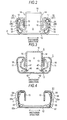
- Fig. 1 and Fig. 2 are a perspective view and a front view showing a vehicle seat sliding apparatus 1 according to an embodiment which is mounted on a vehicle such as an automotive vehicle.
- a lower rail 3 as a first rail is fixed to a vehicle floor 2 in a state of extending in the fore-and-aft direction of the vehicle
- an upper rail 4 as a second rail is mounted on the lower rail 3 so as to be movable relatively to the lower rail 3.
- the lower rail 3 and the upper rail 4 are disposed in pairs respectively in the widthwise direction of a vehicle seat. Then, a seat which forms a seating portion for an occupant is fixed to and supported by the both upper rails 4. The relative movement of the lower rail 3 and the upper rail 4 is normally restricted by a locking member (not shown), and the restriction is released by applying an operating force to the locking member.
- the lower rail 3 includes a pair of side wall portions 11 extending upright from both sides thereof in terms of the widthwise direction and a bottom wall portion 12 as a connecting wall portion which connects proximal ends (lower ends) of the each side wall portion 11. Then, folded-back wall portions 13 as first folded-back wall portions which are formed to protrude inward in terms of the widthwise direction and then folded backward toward the proximal end sides of the side wall portions 11 are formed continuously from distal ends (upper ends) of the respective side wall portions 11.
- the lower rail 3 defines an internal space S opening upward (see Fig. 2 ).
- the upper rail 4 includes a pair of side wall portions 14 extending in the vertical direction between the both folded-back wall portions 13 of the lower rail 3 and a lid wall portion 15 connecting proximal ends (upper ends) of the side wall portions 14.
- folded-back wall portions 16 as second folded-back wall portions which are formed to protrude outward in terms of the widthwise direction and then folded so as to be surrounded by the side wall portions 11 and the folded-back wall portions 13 are formed continuously from distal ends (lower ends) of the respective side wall portions 14.
- the lower rail 3 and the upper rail 4 each include a U-shaped rail cross section with opening sides butted against to each other, and are prevented from coming apart from each other in the longitudinal direction mainly by the engagement of the folded-back wall portions 13 and 16.
- the rail cross section formed by the lower rail 3 and the upper rail 4 assumes so-called a box shape in a rectangular shape.
- retainers 18 each for holding a pair of rolling elements 17 formed of a spherical member and arranged in the vertical direction.
- the each respective rolling element 17 is interposed between the upper end and the lower end of the side wall portion 11 in a state of being abutted against the folded-back wall portion 16.
- the retainers 18 on the respective sides in terms of the widthwise direction are arranged in pair apart from each other on one side and the other side (the lower left side and the upper right side in Fig. 1 ) with the intermediary of a center portion of the lower rail 3 in terms of the longitudinal direction.
- the retainers 18 are arranged symmetrically in terms of the widthwise direction.
- the upper rail 4 is supported so as to be slidable in the longitudinal direction (the fore-and-aft direction of the vehicle) with respect to the lower rail 3 in a state of rolling the rolling elements 17 with respect to the lower rail 3.
- the each side wall portion 11 is formed with a stopper 31 as in-rail functional portions which project into the internal space S to achieve a predetermined function at both end portions thereof in terms of the longitudinal direction.
- the stoppers 31 disposed on the both side wall portions 11 are arranged symmetrically in terms of the widthwise direction.
- the each stopper 31 is cut and raised so that an upper end projects into the internal space S about a lower end as a starting point at an upper side portion of the side wall portion 11 (that is, a portion on the side of the opening of the lower rail 3) and is formed so as to block the path of movement of the each retainer 18 in the longitudinal direction (direction orthogonal to the paper plane) of the lower rail 3 or the like.
- the each stopper 31 functions as a member to prevent the retainer 18 (the rolling element 17) from coming apart in the longitudinal direction of the lower rail 3 or the like.
- a locking hole 32 as a recessed portion is formed around the each stopper 31 in association with the formation (cut and raise) of the stopper 31.
- the each locking hole 32 has a U-shape opened downward according to an outline of the stopper 31.
- the each side wall portion 11 opens in the rail width direction via the locking hole 32, and in appearance, is formed to be depressed inward in the rail width direction by the stopper 31.
- a stopper 36 and a through hole 37 which are similar to the stopper 31 and the locking hole 32 are formed at an intermediate portion of the each side wall portion 11 in terms of the longitudinal direction.
- the each stopper 36 also functions as a member to prevent the retainer 18 (the rolling element 17) from coming apart in the longitudinal direction of the lower rail 3 or the like.
- the stoppers 31 and 36 which prevent the retainer 18 from coming apart are formed by mounting the retainer 18 between the lower rail 3 and the upper rail 4 and then applying a bending process in a state in which the locking hole 32 and the through hole 37 are formed on the lower rail 3 in advance. Therefore, the stoppers 31 and 36 do not interfere with the retainer 18 when it is mounted.
- the each side wall portion 11 is formed with a lock hole 33 which opens in the rail width direction on the lower side of the stopper 31 (the locking hole 32).
- the lower rail 3 is formed with a pair of cut-and-raised strips 41 arranged on the bottom wall portion 12 symmetrically in terms of the widthwise direction at a center portion in terms of the longitudinal direction of the lower rail 3.
- the pair of the cut-and-raised strips 41 are cut and raised at a predetermined angle so as to assume the shape of slanting eyebrows reducing the distance toward the upper ends thereof, and project into the internal space S.
- the respective cut-and-raised strips 41 extend in the longitudinal direction of the lower rail 3, that is, in the direction of the relative movement of the lower rail 3 and the upper rail 4.
- incised portions 42 are formed in association with the formation of the cut-and-raised strips 41 (cut and raised portions) around the respective cut-and-raised strips 41.
- a pair of cut-and-raised strips 46 arranged symmetrically in the widthwise direction are formed at the connecting portion between the side wall portions 14 and the folded-back wall portions 16.
- the pair of the cut-and-raised strips 46 are cut and raised at a predetermined angle so as to assume the shape of slanting eyebrows reducing the distance toward the lower ends thereof, and project into the internal space S.
- the respective cut-and-raised strips 46 extend in the direction of the relative movement of the lower rail 3 and the upper rail 4.
- incised portions 47 are formed in association with the formation of the cut-and-raised strips 46 (cut and raised portions) around the respective cut-and-raised strips 46.
- both cut-and-raised strips 41 and 46 are arranged so that the respective opposed surfaces are able to come into abutment with each other in the direction of the relative movement of the lower rail 3 and the upper rail 4. Therefore, the both cut-and-raised strips 41 and 46, being engaged with each other in association with the relative movement of the lower rail 3 and the upper rail 4, restrict the range which allows the relative movement of the lower rail 3 and the upper rail 4.
- the lower rail 3 is provided with a resin-made protector 51 which covers an end thereof in terms of the longitudinal direction mounted thereon.
- the protector 51 includes a portion-to-be-mounted-on-the-bottom-wall 52 as a connecting wall fitting portion which is mounted on the bottom wall portion 12 in a state of being abutted against a distal end surface of the bottom wall portion 12 in terms of the longitudinal direction, and a pair of portions-to-be-mounted-on-the-side-walls 53 which extend upright from both ends of the portion-to-be-mounted-on-the-bottom-wall 52 in terms of the widthwise direction and are mounted on the both side wall portions 11 and the folded-back wall portion 13 respectively in a state of being abutted against a distal end surfaces of the pair of side wall portions 11 in terms of the longitudinal direction and the distal end surfaces of the proximal end portions of the folded-back wall portions 13.
- the portion-to-be-mounted-on-the-bottom-wall 52 includes an upper extending strip 52a which is brought into a press contact with the upper surface of the bottom wall portion 12 at the center portion in terms of the widthwise direction.
- the respective portions-to-be-mounted-on-the-side-walls 53 have side extending strips 53a which come into a press contact with the outer side surfaces of the proximal end portions of the side wall portions 11 and the folded-back wall portions 13, and each include a projection 54 and a locking claw 55 projecting from the side extending strip 53a inward in terms of the widthwise direction so as to oppose the locking hole 32 and the lock hole 33.
- the projections 54 are provided on the side of the opening of the protector 51 at the both portions-to-be-mounted-on-the-side-walls 53 (side extending strips 53a).
- the protector 51 to be mounted on the end portion of the lower rail 3 in terms of the longitudinal direction is connected to the lower rail 3 by the projections 54 and the locking claws 55 being fitted to the locking holes 32 and the lock holes 33 respectively when the lower rail 3 is being press-fitted to the upper extending strip 52a and the both side extending strips 53a.
- the projections 54 are formed partly in the proximity of or in abutment with the outer side surfaces of the stoppers 31 in association with the fitting with the locking holes 32. Also, as shown in Figs. 5A and 5B , the side extending strips 53a each are formed with a slit 56 extending between the projection 54 and the locking claw 55 from the distal end of the lower rail 3 in terms of the longitudinal direction in the longitudinal direction. Therefore, as shown in Figs. 6A and 6B , in a state in which the process of the stoppers 31 by cutting and raising is not performed, the projections 54 interfere with a portions P of the lower rail 3 where the stoppers 31 should exist, so that the projections 54 and the locking holes 32 cannot be fitted completely and hence the protectors 51 are deformed.
- the protectors 51 are resiliently deformed so that portions of the respective portions-to-be-mounted-on-the-side-walls 53 upper from the slits 56 are lifted with respect to the portions lower than the slits 56, and the opening sides of the both portions-to-be-mounted-on-the-side-walls 53 open.
- the slits 56 accelerate the both portions-to-be-mounted-on-the-side-walls 53 on the opening side to open. Therefore, the unprocessed state of the stoppers 31 can easily be viewed.
- the recessed portion (locking hole 32) formed around the stopper 31 does not have to be opened in the widthwise direction and, for example, it may be the recessed portion depressed in the widthwise direction.
- a protector provided with projections which are fitted to the incised portions 42 as the recessed portions formed around the cut-and-raised strips 41 as the in-rail functional portion is also applicable.
- it may be a protector mounted at the end portion of the upper rail 4 in terms of the longitudinal direction.
- projections which are to be fitted into the incised portions 47 as the recessed portions formed around the cut-and-raised strips 46 as the in-rail functional portions may be provided in the protector.
- the protector may be mounted at both ends of the rail in terms of the longitudinal direction or may be mounted one of the ends thereof.
- the cross-sectional shape of the lower rail 3 is shown simply as an example.
- the folded-back wall portions 13 may be protruded outward in terms of the rail width direction.
- the cross-sectional shape of the upper rail 4 is shown simply as an example.
- the folded-back wall portions 16 may be protruded inward in terms of the rail width direction.
- the cross section of the upper rail 4 is not limited to the U-shape, but may be an inverted T-shape.
- the shape or the number of the rolling elements 17 may be changed as needed. Also the rolling elements 17 may be interposed independently between the lower rail 3 and the upper rail 4 without being held by the retainers 18.
- the positional relation between the lower rail 3 and the upper rail 4 may be upside down.
- a configuration in which the upper rail 4 is fixed to the vehicle floor 2 and the lower rail 3 is fixed to the seat is also applicable.
- the lower rail 3 and the upper rail 4 may be adapted to be disposed one each or three or more each for the seat.
- the direction of movement of the seat in association with the movement of upper rail 4 with respect to the lower rail 3 may be, for example, the fore-and-aft direction or the widthwise direction of the vehicle.
- the second rail includes a stopper portion
- the in-rail functional portion is a cut-and-raised strip which engages the stopper portion in association with the relative movement between the first and second rails and restricts the allowable range of the relative movement between the first and second rails.
- the allowable range of the relative movement between the first and second rails can be restricted by the cut-and-raised strip as the in-rail functional portion.
- a vehicle seat sliding apparatus includes: a first rail adapted to be fixed to any one of a vehicle floor and a seat; and a second rail adapted to be fixed to the other one of the vehicle floor and the seat and adapted to be connected to the first rail so as to be capable of relative movement with respect to the first rail.
- the first rail includes: a pair of side wall portions juxtaposed on both sides in terms of the widthwise direction; a connecting wall portion connecting proximal ends of the both side wall portions; and first folded-back wall portions protruded from distal ends of the both side wall portions in the widthwise direction and then folded back toward proximal end sides of the side wall portions.
- the second rail includes: a pair of second folded-back wall portions protruded from both sides in the widthwise direction and then folded back so as to be surrounded by the side wall portions and the first folded-back wall portions; an in-rail functional portion formed at an end portion of the first rail in terms of the longitudinal direction so as to project into an internal space formed by the first rail to achieve a predetermined function; a recessed portion formed around the in-rail functional portion in association with the formation of the in-rail functional portion; and a protector adapted to be mounted on an end portion of the first rail in terms of the longitudinal direction and cover the end portion thereof.
- the protector is formed with a projection adapted to fit the recessed portion to couple the protector and the first rail.
Landscapes
- Engineering & Computer Science (AREA)
- Aviation & Aerospace Engineering (AREA)
- Transportation (AREA)
- Mechanical Engineering (AREA)
- Seats For Vehicles (AREA)
- Train Traffic Observation, Control, And Security (AREA)
Applications Claiming Priority (1)
| Application Number | Priority Date | Filing Date | Title |
|---|---|---|---|
| JP2008263016A JP5277850B2 (ja) | 2008-10-09 | 2008-10-09 | 車両用シートスライド装置 |
Publications (3)
| Publication Number | Publication Date |
|---|---|
| EP2174827A2 true EP2174827A2 (fr) | 2010-04-14 |
| EP2174827A3 EP2174827A3 (fr) | 2014-10-22 |
| EP2174827B1 EP2174827B1 (fr) | 2015-10-21 |
Family
ID=41667207
Family Applications (1)
| Application Number | Title | Priority Date | Filing Date |
|---|---|---|---|
| EP09171654.8A Active EP2174827B1 (fr) | 2008-10-09 | 2009-09-29 | Appareil coulissant de siège de véhicule |
Country Status (4)
| Country | Link |
|---|---|
| US (1) | US7815159B2 (fr) |
| EP (1) | EP2174827B1 (fr) |
| JP (1) | JP5277850B2 (fr) |
| CN (1) | CN101716895B (fr) |
Cited By (5)
| Publication number | Priority date | Publication date | Assignee | Title |
|---|---|---|---|---|
| FR2994902A1 (fr) * | 2012-08-28 | 2014-03-07 | Faurecia Sieges Automobile | Glissiere et procede de realisation d'une glissiere pour siege de vehicule automobile |
| CN104071039A (zh) * | 2013-03-27 | 2014-10-01 | 李尔公司 | 座椅轨道端盖和行进阻挡座椅位置传感器 |
| WO2016096486A1 (fr) * | 2014-12-16 | 2016-06-23 | Johnson Controls Metals and Mechanisms GmbH & Co. KG | Recouvrement pour une paire de rails d'un siège de véhicule ajustable en longueur, ainsi que paire de rails |
| US9469217B2 (en) | 2013-09-30 | 2016-10-18 | Toyota Boshoku Kabushiki Kaisha | Vehicle seat |
| US10259346B2 (en) | 2016-07-22 | 2019-04-16 | Toyota Boshoku Kabushiki Kaisha | Seat sliding device |
Families Citing this family (23)
| Publication number | Priority date | Publication date | Assignee | Title |
|---|---|---|---|---|
| GB0616733D0 (en) * | 2006-08-23 | 2006-10-04 | Accuride Int Ltd | A sliding support assembly |
| JP2009101955A (ja) * | 2007-10-25 | 2009-05-14 | Aisin Seiki Co Ltd | 車両用シートスライド装置 |
| JP5293026B2 (ja) * | 2008-09-12 | 2013-09-18 | アイシン精機株式会社 | 車両用パワーシート装置 |
| FR2958230B1 (fr) * | 2010-04-02 | 2012-04-13 | Faurecia Sieges Automobile | Glissiere pour siege de vehicule et siege comportant une telle glissiere. |
| FR2962384B1 (fr) * | 2010-07-08 | 2012-09-07 | Faurecia Sieges Automobile | Glissiere de siege de vehicule |
| KR101316439B1 (ko) * | 2010-11-30 | 2013-10-08 | 주식회사 동희산업 | 펜턴트형 조정식 오르간 엑셀 페달장치 |
| DE102010055244B4 (de) * | 2010-12-20 | 2012-08-30 | Keiper Gmbh & Co. Kg | Längseinstellbarer Fahrzeugsitz |
| US20120186375A1 (en) * | 2011-01-20 | 2012-07-26 | Summer Infant (Usa), Inc. | Manual Height Adjustable Assembly For A Crib |
| FR2973747B1 (fr) * | 2011-04-05 | 2013-05-03 | Faurecia Sieges Automobile | Entretoise et profile pour glissiere de siege de vehicule automobile |
| DE102012201584B4 (de) * | 2012-02-03 | 2021-04-01 | Lear Corporation | Sitzschienenanordnung mit wählbaren Endanschlag-Positionen und Verfahren zum Ausbilden einer Sitzschienenanordnung |
| US9387779B2 (en) | 2012-10-25 | 2016-07-12 | Lear Corporation | Seat track assembly having selectable end stop positions |
| JP6237304B2 (ja) * | 2014-02-12 | 2017-11-29 | アイシン精機株式会社 | 車両用シートスライド装置 |
| US10160350B2 (en) | 2015-06-30 | 2018-12-25 | Brose Fahrzeugteile Gmbh & Co. Kg, Coburg | Adjusting device for longitudinal adjustment of a vehicle seat and method for assembly |
| CN108136939B (zh) * | 2015-08-03 | 2021-02-05 | 延锋安道拓座椅机械部件有限公司 | 用于可纵向调节的座椅的轨道的止动件 |
| US10005376B2 (en) * | 2016-03-08 | 2018-06-26 | Honda Motor Co., Ltd. | Vehicle seat |
| DE102016208364B4 (de) * | 2016-05-17 | 2021-11-18 | Lear Corporation | Sitzschienenanordnung und Verfahren zur Herstellung einer Sitzschienenanordnung |
| JP6861491B2 (ja) | 2016-09-16 | 2021-04-21 | シロキ工業株式会社 | シートトラック |
| DE102016225818B4 (de) * | 2016-09-21 | 2021-05-12 | Adient Luxembourg Holding S.À R.L. | Längseinsteller sowie Fahrzeugsitz |
| DE102016225822A1 (de) * | 2016-09-21 | 2018-03-22 | Adient Luxembourg Holding S.a.r.l. | Sitzschienenpaar für einen Fahrzeugsitz |
| US10950977B2 (en) * | 2018-12-18 | 2021-03-16 | Lear Corporation | Track assembly for a vehicle component |
| DE102019120364B4 (de) * | 2019-03-20 | 2021-11-04 | Adient Engineering and IP GmbH | Endkappe für eine schiene sowie längseinsteller |
| JP7378301B2 (ja) * | 2020-01-23 | 2023-11-13 | 株式会社Tf-Metal | シートスライド装置 |
| JP7558853B2 (ja) * | 2021-03-18 | 2024-10-01 | トヨタ紡織精工株式会社 | シートスライド装置 |
Citations (2)
| Publication number | Priority date | Publication date | Assignee | Title |
|---|---|---|---|---|
| JP2005008065A (ja) | 2003-06-19 | 2005-01-13 | Nhk Spring Co Ltd | 車両用シートのスライドレール構造 |
| JP2006298104A (ja) | 2005-04-19 | 2006-11-02 | Shiroki Corp | シートトラック装置 |
Family Cites Families (15)
| Publication number | Priority date | Publication date | Assignee | Title |
|---|---|---|---|---|
| US5209447A (en) * | 1991-11-15 | 1993-05-11 | Tachi-S Co., Ltd. | Cover structure for slide rail in seat adjuster |
| JP3148801B2 (ja) * | 1996-05-22 | 2001-03-26 | 池田物産株式会社 | シートスライド装置 |
| JPH115467A (ja) * | 1997-06-16 | 1999-01-12 | Oi Seisakusho Co Ltd | シートスライド装置 |
| JPH11129789A (ja) * | 1997-10-27 | 1999-05-18 | Ikeda Bussan Co Ltd | パワーシートスライド装置 |
| JPH11189076A (ja) * | 1997-12-25 | 1999-07-13 | Aisin Seiki Co Ltd | 車両用シートスライド装置 |
| JPH11301316A (ja) * | 1998-04-23 | 1999-11-02 | Tachi S Co Ltd | シート・トラック |
| FR2847530B1 (fr) * | 2002-11-25 | 2005-03-11 | Faurecia Sieges Automobile | Glissiere pour siege de vehicule automobile et siege de vehicule comprenant une telle glissiere |
| JP4220348B2 (ja) * | 2003-10-20 | 2009-02-04 | シロキ工業株式会社 | シートトラック |
| FR2863959B1 (fr) * | 2003-12-18 | 2006-04-07 | Faurecia Sieges Automobile | Glissiere pour siege de vehicule et siege de vehicule comprenant une telle glissiere |
| JP4521638B2 (ja) * | 2005-03-22 | 2010-08-11 | 株式会社今仙電機製作所 | シートレール装置 |
| JP4797625B2 (ja) * | 2005-12-28 | 2011-10-19 | アイシン精機株式会社 | 車両用シートスライド装置 |
| JP4939810B2 (ja) * | 2006-01-27 | 2012-05-30 | 富士機工株式会社 | 車両のシートスライド装置 |
| KR100781502B1 (ko) * | 2006-02-08 | 2007-11-30 | 다이모스(주) | 차량용 시트레일 |
| JP2008179265A (ja) * | 2007-01-25 | 2008-08-07 | Fuji Kiko Co Ltd | 車両のシートスライド装置 |
| DE102008034788B4 (de) * | 2008-02-28 | 2012-06-14 | Lear Corporation | Sitzanordnung und Längs-Sitzverstellvorrichtung für einen Fahrzeugsitz |
-
2008
- 2008-10-09 JP JP2008263016A patent/JP5277850B2/ja active Active
-
2009
- 2009-09-27 CN CN2009101750803A patent/CN101716895B/zh active Active
- 2009-09-29 EP EP09171654.8A patent/EP2174827B1/fr active Active
- 2009-09-29 US US12/569,358 patent/US7815159B2/en active Active
Patent Citations (2)
| Publication number | Priority date | Publication date | Assignee | Title |
|---|---|---|---|---|
| JP2005008065A (ja) | 2003-06-19 | 2005-01-13 | Nhk Spring Co Ltd | 車両用シートのスライドレール構造 |
| JP2006298104A (ja) | 2005-04-19 | 2006-11-02 | Shiroki Corp | シートトラック装置 |
Cited By (11)
| Publication number | Priority date | Publication date | Assignee | Title |
|---|---|---|---|---|
| FR2994902A1 (fr) * | 2012-08-28 | 2014-03-07 | Faurecia Sieges Automobile | Glissiere et procede de realisation d'une glissiere pour siege de vehicule automobile |
| CN104071039A (zh) * | 2013-03-27 | 2014-10-01 | 李尔公司 | 座椅轨道端盖和行进阻挡座椅位置传感器 |
| US20140291473A1 (en) * | 2013-03-27 | 2014-10-02 | Lear Corporation | Seat track end cap and travel stop seat position sensor |
| US9102245B2 (en) * | 2013-03-27 | 2015-08-11 | Lear Corporation | Seat track end cap and travel stop seat position sensor |
| CN104071039B (zh) * | 2013-03-27 | 2016-11-23 | 李尔公司 | 座椅轨道端盖和行进阻挡座椅位置传感器 |
| US9469217B2 (en) | 2013-09-30 | 2016-10-18 | Toyota Boshoku Kabushiki Kaisha | Vehicle seat |
| DE102014219233B4 (de) * | 2013-09-30 | 2020-09-03 | Toyota Boshoku Kabushiki Kaisha | Fahrzeugsitz |
| WO2016096486A1 (fr) * | 2014-12-16 | 2016-06-23 | Johnson Controls Metals and Mechanisms GmbH & Co. KG | Recouvrement pour une paire de rails d'un siège de véhicule ajustable en longueur, ainsi que paire de rails |
| US10399464B2 (en) | 2014-12-16 | 2019-09-03 | Adient Luxembourg Holding S.à. r. l. | Cover for a rail pair of a longitudinally adjustable vehicle seat and rail pair |
| US10259346B2 (en) | 2016-07-22 | 2019-04-16 | Toyota Boshoku Kabushiki Kaisha | Seat sliding device |
| DE102017212372B4 (de) | 2016-07-22 | 2022-02-24 | Toyota Boshoku Kabushiki Kaisha | Sitzgleitvorrichtung |
Also Published As
| Publication number | Publication date |
|---|---|
| CN101716895B (zh) | 2012-11-21 |
| JP2010089689A (ja) | 2010-04-22 |
| JP5277850B2 (ja) | 2013-08-28 |
| US20100090084A1 (en) | 2010-04-15 |
| EP2174827B1 (fr) | 2015-10-21 |
| CN101716895A (zh) | 2010-06-02 |
| EP2174827A3 (fr) | 2014-10-22 |
| US7815159B2 (en) | 2010-10-19 |
Similar Documents
| Publication | Publication Date | Title |
|---|---|---|
| EP2174827B1 (fr) | Appareil coulissant de siège de véhicule | |
| EP2177391B1 (fr) | Appareil coulissant de siège de véhicule | |
| JP5181595B2 (ja) | 車両用シートスライド装置 | |
| US7594635B2 (en) | Seat sliding apparatus for vehicle | |
| US8490941B2 (en) | Seat slide apparatus for vehicle | |
| US8201798B2 (en) | Seat slide apparatus for vehicle | |
| US9446698B2 (en) | Vehicle seat | |
| EP2189324B1 (fr) | Dispositif de coulissement de siège de véhicule | |
| JP2013052842A (ja) | 車両用シートスライド装置 | |
| US10099589B2 (en) | Headrest guide | |
| KR20060124684A (ko) | 모듈 홀더에 커넥터 모듈을 체결시키기 위한 장치 | |
| US20050082794A1 (en) | Air bag module with adjustable cover | |
| JPH0884634A (ja) | ヘッドレスト高さ調整装置 | |
| JP2008302895A (ja) | 自動車のピラートリム取付構造 | |
| JP4414019B2 (ja) | 配線ダクトカバーの外れ止め装置 | |
| JPH0546970Y2 (fr) | ||
| JP5188271B2 (ja) | カバー構造 | |
| JPH0616831Y2 (ja) | 車両用灰皿の組付部構造 | |
| KR20100027260A (ko) | 자동차용 시트의 헤드레스트 폴 가이드 부쉬 | |
| JP2001001801A (ja) | 車両用シート | |
| KR20180039413A (ko) | 차량용 슬라이딩 암레스트 | |
| JP2006231989A (ja) | ボックス用リッドの取付構造 | |
| JPH099422A (ja) | ボックス | |
| JP2009001141A (ja) | シートベルトショルダーアンカー装置の組付構造 | |
| JPH0512255U (ja) | 車両座席用スライドレール装置 |
Legal Events
| Date | Code | Title | Description |
|---|---|---|---|
| PUAI | Public reference made under article 153(3) epc to a published international application that has entered the european phase |
Free format text: ORIGINAL CODE: 0009012 |
|
| AK | Designated contracting states |
Kind code of ref document: A2 Designated state(s): AT BE BG CH CY CZ DE DK EE ES FI FR GB GR HR HU IE IS IT LI LT LU LV MC MK MT NL NO PL PT RO SE SI SK SM TR |
|
| AX | Request for extension of the european patent |
Extension state: AL BA RS |
|
| PUAL | Search report despatched |
Free format text: ORIGINAL CODE: 0009013 |
|
| AK | Designated contracting states |
Kind code of ref document: A3 Designated state(s): AT BE BG CH CY CZ DE DK EE ES FI FR GB GR HR HU IE IS IT LI LT LU LV MC MK MT NL NO PL PT RO SE SI SK SM TR |
|
| AX | Request for extension of the european patent |
Extension state: AL BA RS |
|
| RIC1 | Information provided on ipc code assigned before grant |
Ipc: B60N 2/07 20060101AFI20140916BHEP |
|
| 17P | Request for examination filed |
Effective date: 20141006 |
|
| RBV | Designated contracting states (corrected) |
Designated state(s): AT BE BG CH CY CZ DE DK EE ES FI FR GB GR HR HU IE IS IT LI LT LU LV MC MK MT NL NO PL PT RO SE SI SK SM TR |
|
| GRAP | Despatch of communication of intention to grant a patent |
Free format text: ORIGINAL CODE: EPIDOSNIGR1 |
|
| INTG | Intention to grant announced |
Effective date: 20150417 |
|
| GRAS | Grant fee paid |
Free format text: ORIGINAL CODE: EPIDOSNIGR3 |
|
| GRAA | (expected) grant |
Free format text: ORIGINAL CODE: 0009210 |
|
| AK | Designated contracting states |
Kind code of ref document: B1 Designated state(s): AT BE BG CH CY CZ DE DK EE ES FI FR GB GR HR HU IE IS IT LI LT LU LV MC MK MT NL NO PL PT RO SE SI SK SM TR |
|
| REG | Reference to a national code |
Ref country code: GB Ref legal event code: FG4D Ref country code: NL Ref legal event code: MP Effective date: 20151021 |
|
| REG | Reference to a national code |
Ref country code: CH Ref legal event code: EP |
|
| REG | Reference to a national code |
Ref country code: AT Ref legal event code: REF Ref document number: 756381 Country of ref document: AT Kind code of ref document: T Effective date: 20151115 |
|
| REG | Reference to a national code |
Ref country code: IE Ref legal event code: FG4D |
|
| REG | Reference to a national code |
Ref country code: DE Ref legal event code: R096 Ref document number: 602009034318 Country of ref document: DE |
|
| REG | Reference to a national code |
Ref country code: LT Ref legal event code: MG4D |
|
| REG | Reference to a national code |
Ref country code: AT Ref legal event code: MK05 Ref document number: 756381 Country of ref document: AT Kind code of ref document: T Effective date: 20151021 |
|
| PG25 | Lapsed in a contracting state [announced via postgrant information from national office to epo] |
Ref country code: IS Free format text: LAPSE BECAUSE OF FAILURE TO SUBMIT A TRANSLATION OF THE DESCRIPTION OR TO PAY THE FEE WITHIN THE PRESCRIBED TIME-LIMIT Effective date: 20160221 Ref country code: NL Free format text: LAPSE BECAUSE OF FAILURE TO SUBMIT A TRANSLATION OF THE DESCRIPTION OR TO PAY THE FEE WITHIN THE PRESCRIBED TIME-LIMIT Effective date: 20151021 Ref country code: NO Free format text: LAPSE BECAUSE OF FAILURE TO SUBMIT A TRANSLATION OF THE DESCRIPTION OR TO PAY THE FEE WITHIN THE PRESCRIBED TIME-LIMIT Effective date: 20160121 Ref country code: HR Free format text: LAPSE BECAUSE OF FAILURE TO SUBMIT A TRANSLATION OF THE DESCRIPTION OR TO PAY THE FEE WITHIN THE PRESCRIBED TIME-LIMIT Effective date: 20151021 Ref country code: LT Free format text: LAPSE BECAUSE OF FAILURE TO SUBMIT A TRANSLATION OF THE DESCRIPTION OR TO PAY THE FEE WITHIN THE PRESCRIBED TIME-LIMIT Effective date: 20151021 Ref country code: IT Free format text: LAPSE BECAUSE OF FAILURE TO SUBMIT A TRANSLATION OF THE DESCRIPTION OR TO PAY THE FEE WITHIN THE PRESCRIBED TIME-LIMIT Effective date: 20151021 Ref country code: ES Free format text: LAPSE BECAUSE OF FAILURE TO SUBMIT A TRANSLATION OF THE DESCRIPTION OR TO PAY THE FEE WITHIN THE PRESCRIBED TIME-LIMIT Effective date: 20151021 |
|
| PG25 | Lapsed in a contracting state [announced via postgrant information from national office to epo] |
Ref country code: LV Free format text: LAPSE BECAUSE OF FAILURE TO SUBMIT A TRANSLATION OF THE DESCRIPTION OR TO PAY THE FEE WITHIN THE PRESCRIBED TIME-LIMIT Effective date: 20151021 Ref country code: SE Free format text: LAPSE BECAUSE OF FAILURE TO SUBMIT A TRANSLATION OF THE DESCRIPTION OR TO PAY THE FEE WITHIN THE PRESCRIBED TIME-LIMIT Effective date: 20151021 Ref country code: GR Free format text: LAPSE BECAUSE OF FAILURE TO SUBMIT A TRANSLATION OF THE DESCRIPTION OR TO PAY THE FEE WITHIN THE PRESCRIBED TIME-LIMIT Effective date: 20160122 Ref country code: PT Free format text: LAPSE BECAUSE OF FAILURE TO SUBMIT A TRANSLATION OF THE DESCRIPTION OR TO PAY THE FEE WITHIN THE PRESCRIBED TIME-LIMIT Effective date: 20160222 Ref country code: FI Free format text: LAPSE BECAUSE OF FAILURE TO SUBMIT A TRANSLATION OF THE DESCRIPTION OR TO PAY THE FEE WITHIN THE PRESCRIBED TIME-LIMIT Effective date: 20151021 Ref country code: PL Free format text: LAPSE BECAUSE OF FAILURE TO SUBMIT A TRANSLATION OF THE DESCRIPTION OR TO PAY THE FEE WITHIN THE PRESCRIBED TIME-LIMIT Effective date: 20151021 Ref country code: AT Free format text: LAPSE BECAUSE OF FAILURE TO SUBMIT A TRANSLATION OF THE DESCRIPTION OR TO PAY THE FEE WITHIN THE PRESCRIBED TIME-LIMIT Effective date: 20151021 |
|
| REG | Reference to a national code |
Ref country code: DE Ref legal event code: R097 Ref document number: 602009034318 Country of ref document: DE |
|
| PG25 | Lapsed in a contracting state [announced via postgrant information from national office to epo] |
Ref country code: CZ Free format text: LAPSE BECAUSE OF FAILURE TO SUBMIT A TRANSLATION OF THE DESCRIPTION OR TO PAY THE FEE WITHIN THE PRESCRIBED TIME-LIMIT Effective date: 20151021 |
|
| REG | Reference to a national code |
Ref country code: FR Ref legal event code: PLFP Year of fee payment: 8 |
|
| PLBE | No opposition filed within time limit |
Free format text: ORIGINAL CODE: 0009261 |
|
| STAA | Information on the status of an ep patent application or granted ep patent |
Free format text: STATUS: NO OPPOSITION FILED WITHIN TIME LIMIT |
|
| PG25 | Lapsed in a contracting state [announced via postgrant information from national office to epo] |
Ref country code: RO Free format text: LAPSE BECAUSE OF FAILURE TO SUBMIT A TRANSLATION OF THE DESCRIPTION OR TO PAY THE FEE WITHIN THE PRESCRIBED TIME-LIMIT Effective date: 20151021 Ref country code: SK Free format text: LAPSE BECAUSE OF FAILURE TO SUBMIT A TRANSLATION OF THE DESCRIPTION OR TO PAY THE FEE WITHIN THE PRESCRIBED TIME-LIMIT Effective date: 20151021 Ref country code: DK Free format text: LAPSE BECAUSE OF FAILURE TO SUBMIT A TRANSLATION OF THE DESCRIPTION OR TO PAY THE FEE WITHIN THE PRESCRIBED TIME-LIMIT Effective date: 20151021 Ref country code: EE Free format text: LAPSE BECAUSE OF FAILURE TO SUBMIT A TRANSLATION OF THE DESCRIPTION OR TO PAY THE FEE WITHIN THE PRESCRIBED TIME-LIMIT Effective date: 20151021 Ref country code: SM Free format text: LAPSE BECAUSE OF FAILURE TO SUBMIT A TRANSLATION OF THE DESCRIPTION OR TO PAY THE FEE WITHIN THE PRESCRIBED TIME-LIMIT Effective date: 20151021 |
|
| 26N | No opposition filed |
Effective date: 20160722 |
|
| PG25 | Lapsed in a contracting state [announced via postgrant information from national office to epo] |
Ref country code: SI Free format text: LAPSE BECAUSE OF FAILURE TO SUBMIT A TRANSLATION OF THE DESCRIPTION OR TO PAY THE FEE WITHIN THE PRESCRIBED TIME-LIMIT Effective date: 20151021 |
|
| PG25 | Lapsed in a contracting state [announced via postgrant information from national office to epo] |
Ref country code: BE Free format text: LAPSE BECAUSE OF FAILURE TO SUBMIT A TRANSLATION OF THE DESCRIPTION OR TO PAY THE FEE WITHIN THE PRESCRIBED TIME-LIMIT Effective date: 20151021 |
|
| PG25 | Lapsed in a contracting state [announced via postgrant information from national office to epo] |
Ref country code: MC Free format text: LAPSE BECAUSE OF FAILURE TO SUBMIT A TRANSLATION OF THE DESCRIPTION OR TO PAY THE FEE WITHIN THE PRESCRIBED TIME-LIMIT Effective date: 20151021 |
|
| REG | Reference to a national code |
Ref country code: CH Ref legal event code: PL |
|
| GBPC | Gb: european patent ceased through non-payment of renewal fee |
Effective date: 20160929 |
|
| REG | Reference to a national code |
Ref country code: IE Ref legal event code: MM4A |
|
| PG25 | Lapsed in a contracting state [announced via postgrant information from national office to epo] |
Ref country code: GB Free format text: LAPSE BECAUSE OF NON-PAYMENT OF DUE FEES Effective date: 20160929 Ref country code: CH Free format text: LAPSE BECAUSE OF NON-PAYMENT OF DUE FEES Effective date: 20160930 Ref country code: IE Free format text: LAPSE BECAUSE OF NON-PAYMENT OF DUE FEES Effective date: 20160929 Ref country code: LI Free format text: LAPSE BECAUSE OF NON-PAYMENT OF DUE FEES Effective date: 20160930 |
|
| REG | Reference to a national code |
Ref country code: FR Ref legal event code: PLFP Year of fee payment: 9 |
|
| PG25 | Lapsed in a contracting state [announced via postgrant information from national office to epo] |
Ref country code: LU Free format text: LAPSE BECAUSE OF NON-PAYMENT OF DUE FEES Effective date: 20160929 |
|
| REG | Reference to a national code |
Ref country code: DE Ref legal event code: R084 Ref document number: 602009034318 Country of ref document: DE |
|
| PG25 | Lapsed in a contracting state [announced via postgrant information from national office to epo] |
Ref country code: CY Free format text: LAPSE BECAUSE OF FAILURE TO SUBMIT A TRANSLATION OF THE DESCRIPTION OR TO PAY THE FEE WITHIN THE PRESCRIBED TIME-LIMIT Effective date: 20151021 Ref country code: HU Free format text: LAPSE BECAUSE OF FAILURE TO SUBMIT A TRANSLATION OF THE DESCRIPTION OR TO PAY THE FEE WITHIN THE PRESCRIBED TIME-LIMIT; INVALID AB INITIO Effective date: 20090929 |
|
| PG25 | Lapsed in a contracting state [announced via postgrant information from national office to epo] |
Ref country code: MT Free format text: LAPSE BECAUSE OF NON-PAYMENT OF DUE FEES Effective date: 20160930 Ref country code: TR Free format text: LAPSE BECAUSE OF FAILURE TO SUBMIT A TRANSLATION OF THE DESCRIPTION OR TO PAY THE FEE WITHIN THE PRESCRIBED TIME-LIMIT Effective date: 20151021 Ref country code: MK Free format text: LAPSE BECAUSE OF FAILURE TO SUBMIT A TRANSLATION OF THE DESCRIPTION OR TO PAY THE FEE WITHIN THE PRESCRIBED TIME-LIMIT Effective date: 20151021 |
|
| PG25 | Lapsed in a contracting state [announced via postgrant information from national office to epo] |
Ref country code: BG Free format text: LAPSE BECAUSE OF FAILURE TO SUBMIT A TRANSLATION OF THE DESCRIPTION OR TO PAY THE FEE WITHIN THE PRESCRIBED TIME-LIMIT Effective date: 20151021 |
|
| REG | Reference to a national code |
Ref country code: FR Ref legal event code: PLFP Year of fee payment: 10 |
|
| REG | Reference to a national code |
Ref country code: DE Ref legal event code: R081 Ref document number: 602009034318 Country of ref document: DE Owner name: TOYOTA BOSHOKU KABUSHIKI KAISHA, KARIYA-SHI, JP Free format text: FORMER OWNER: AISIN SEIKI K.K., KARIYA-SHI, AICHI, JP |
|
| PGFP | Annual fee paid to national office [announced via postgrant information from national office to epo] |
Ref country code: DE Payment date: 20250805 Year of fee payment: 17 |
|
| PGFP | Annual fee paid to national office [announced via postgrant information from national office to epo] |
Ref country code: FR Payment date: 20250808 Year of fee payment: 17 |