EP2174834A2 - Mänovrierhilfsvorrichtung - Google Patents
Mänovrierhilfsvorrichtung Download PDFInfo
- Publication number
- EP2174834A2 EP2174834A2 EP09012775A EP09012775A EP2174834A2 EP 2174834 A2 EP2174834 A2 EP 2174834A2 EP 09012775 A EP09012775 A EP 09012775A EP 09012775 A EP09012775 A EP 09012775A EP 2174834 A2 EP2174834 A2 EP 2174834A2
- Authority
- EP
- European Patent Office
- Prior art keywords
- image
- ship
- bird
- eye view
- moving
- Prior art date
- Legal status (The legal status is an assumption and is not a legal conclusion. Google has not performed a legal analysis and makes no representation as to the accuracy of the status listed.)
- Withdrawn
Links
- 238000001514 detection method Methods 0.000 claims description 2
- 235000004522 Pentaglottis sempervirens Nutrition 0.000 abstract description 81
- 230000000007 visual effect Effects 0.000 description 26
- 238000000034 method Methods 0.000 description 22
- 230000009466 transformation Effects 0.000 description 18
- 238000003384 imaging method Methods 0.000 description 12
- XLYOFNOQVPJJNP-UHFFFAOYSA-N water Substances O XLYOFNOQVPJJNP-UHFFFAOYSA-N 0.000 description 10
- 230000003287 optical effect Effects 0.000 description 6
- 239000011159 matrix material Substances 0.000 description 4
- 230000003247 decreasing effect Effects 0.000 description 3
- 238000010586 diagram Methods 0.000 description 2
- 238000009434 installation Methods 0.000 description 2
- 230000007423 decrease Effects 0.000 description 1
- 230000001131 transforming effect Effects 0.000 description 1
Images


Classifications
-
- B—PERFORMING OPERATIONS; TRANSPORTING
- B63—SHIPS OR OTHER WATERBORNE VESSELS; RELATED EQUIPMENT
- B63B—SHIPS OR OTHER WATERBORNE VESSELS; EQUIPMENT FOR SHIPPING
- B63B49/00—Arrangements of nautical instruments or navigational aids
-
- B—PERFORMING OPERATIONS; TRANSPORTING
- B60—VEHICLES IN GENERAL
- B60R—VEHICLES, VEHICLE FITTINGS, OR VEHICLE PARTS, NOT OTHERWISE PROVIDED FOR
- B60R2300/00—Details of viewing arrangements using cameras and displays, specially adapted for use in a vehicle
- B60R2300/10—Details of viewing arrangements using cameras and displays, specially adapted for use in a vehicle characterised by the type of camera system used
- B60R2300/102—Details of viewing arrangements using cameras and displays, specially adapted for use in a vehicle characterised by the type of camera system used using 360 degree surveillance camera system
-
- B—PERFORMING OPERATIONS; TRANSPORTING
- B60—VEHICLES IN GENERAL
- B60R—VEHICLES, VEHICLE FITTINGS, OR VEHICLE PARTS, NOT OTHERWISE PROVIDED FOR
- B60R2300/00—Details of viewing arrangements using cameras and displays, specially adapted for use in a vehicle
- B60R2300/10—Details of viewing arrangements using cameras and displays, specially adapted for use in a vehicle characterised by the type of camera system used
- B60R2300/105—Details of viewing arrangements using cameras and displays, specially adapted for use in a vehicle characterised by the type of camera system used using multiple cameras
-
- B—PERFORMING OPERATIONS; TRANSPORTING
- B60—VEHICLES IN GENERAL
- B60R—VEHICLES, VEHICLE FITTINGS, OR VEHICLE PARTS, NOT OTHERWISE PROVIDED FOR
- B60R2300/00—Details of viewing arrangements using cameras and displays, specially adapted for use in a vehicle
- B60R2300/30—Details of viewing arrangements using cameras and displays, specially adapted for use in a vehicle characterised by the type of image processing
- B60R2300/303—Details of viewing arrangements using cameras and displays, specially adapted for use in a vehicle characterised by the type of image processing using joined images, e.g. multiple camera images
-
- B—PERFORMING OPERATIONS; TRANSPORTING
- B60—VEHICLES IN GENERAL
- B60R—VEHICLES, VEHICLE FITTINGS, OR VEHICLE PARTS, NOT OTHERWISE PROVIDED FOR
- B60R2300/00—Details of viewing arrangements using cameras and displays, specially adapted for use in a vehicle
- B60R2300/30—Details of viewing arrangements using cameras and displays, specially adapted for use in a vehicle characterised by the type of image processing
- B60R2300/304—Details of viewing arrangements using cameras and displays, specially adapted for use in a vehicle characterised by the type of image processing using merged images, e.g. merging camera image with stored images
- B60R2300/305—Details of viewing arrangements using cameras and displays, specially adapted for use in a vehicle characterised by the type of image processing using merged images, e.g. merging camera image with stored images merging camera image with lines or icons
-
- B—PERFORMING OPERATIONS; TRANSPORTING
- B60—VEHICLES IN GENERAL
- B60R—VEHICLES, VEHICLE FITTINGS, OR VEHICLE PARTS, NOT OTHERWISE PROVIDED FOR
- B60R2300/00—Details of viewing arrangements using cameras and displays, specially adapted for use in a vehicle
- B60R2300/60—Details of viewing arrangements using cameras and displays, specially adapted for use in a vehicle characterised by monitoring and displaying vehicle exterior scenes from a transformed perspective
- B60R2300/607—Details of viewing arrangements using cameras and displays, specially adapted for use in a vehicle characterised by monitoring and displaying vehicle exterior scenes from a transformed perspective from a bird's eye viewpoint
Definitions
- the present invention relates to a maneuvering assisting apparatus. More particularly, the present invention relates to a maneuvering assisting apparatus for assisting in maneuvering a moving object by displaying a bird's eye view image of the moving object on a monitor screen
- a plurality of cameras are installed in a vehicle, and an image of which the view point is above the vehicle is created based on output of these cameras.
- the image thus created is displayed on a monitor screen.
- Four corner sensors are installed one each at four corners of the vehicle. When an obstacle approaching the vehicle is sensed by any of these corner sensors, a predetermined mark is displayed on the monitor screen corresponding to an installation position of the corner sensor that has sensed the obstacle. This allows a driver to recognize an existence of the obstacle through the monitor screen.
- a primary object of the present invention is to provide a maneuvering assisting apparatus capable of improving maneuverability.
- a maneuvering assisting apparatus comprises: an imager, arranged in a downward attitude in a moving object, which captures surroundings of the moving object; a creator which creates a surrounding image representing in an aerially viewed manner the surroundings of the moving object, based on output of the imager; and a first multiplexer which transparently multiplexes a first moving-object image representing at least an extension of the aerially viewed moving object, onto the surrounding image created by the creator.
- the first moving-object image representing at least the extension of the aerially viewed moving object is multiplexed onto the surrounding image representing in an aerially viewed manner the surroundings of the moving object, a positional relationship between the moving object and its surroundings becomes clear. Moreover, when the first moving-object image is transparently multiplexed, a blind spot in the surroundings of the moving object is decreased. As a result, a maneuverability of the moving object is improved.
- the first moving-object image is equivalent to an image representing a whole of the aerially viewed moving object
- a second multiplexer which multiplexes a second moving-object image representing one portion ofthe aerially viewed moving object, onto the surrounding image created by the creator.
- the second multiplexer non-transparently multiplexes the second moving-object image.
- the moving object is equivalent to a ship, and a size of one portion of the moving object represented by the second moving-object image is equivalent to a size of a cut-out surface obtained by cutting out the moving object with a draft line.
- a maneuvering assisting apparatus further comprised are: an inclination detector which detects a change in inclination and/or altitude of the moving object; and a corrector which corrects the size of one portion of the moving object represented by the second moving-object image, with reference to a detection result of the inclination detector.
- a ship-maneuvering assisting apparatus 10 of this embodiment shown in Figure 1 includes four cameras C_1 to C_4. Each of the cameras C_1 to C_4 outputs object scene images P_1 to P_4 in synchronization with a common timing signal at every 1/30 seconds. The outputted object scene images P_1 to P_4 are fetched by an image processing circuit 12.
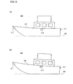
- the ship-maneuvering assisting apparatus 10 is loaded in a ship 100 shown in Figure 2(A) and Figure 2(B) , and Figure 3(A) and Figure 3(B) .
- the ship 100 is configured by a ship hull 102, a cabin 104, and a navigation bridge 106.
- a cross section, obtained by cutting the ship hull 102 orthogonal to a height direction, has a width that increases concurrently with an increase in altitude.
- the cabin 104 is formed in a box shape at a substantially center of a top surface of the ship hull 102, and the navigation bridge 106 is formed in a box shape at a top-surface center of the cabin 104.
- a width of the cabin 104 is smaller than that of the top surface of the ship hull 102, and a width of the navigation bridge 106 is also smaller than that of the cabin 104.
- the camera C_1 is installed at a leading end, i.e., a bow, ofthe ship hull 102, and the camera C_2 is installed at a substantially center in a length direction of a starboard upper portion of the ship hull 102. Furthermore, the camera C_3 is installed at an upper portion center of a rear surface of the ship hull 102, and the camera C_4 is installed at a substantially center in a length direction of a port upper portion of the ship hull 102.
- An optical axis of the camera C_1 extends obliquely downward forward of the ship hull 102, and an optical axis of the camera C_2 extends obliquely downward rightward ofthe ship hull 102.
- an optical axis of the camera C_3 extends obliquely downward rearward of the ship hull 102
- an optical axis of the camera C_4 extends obliquely downward leftward of the ship hull 102.
- the camera C_1 has a visual field VW_1 capturing a front side of the ship hull 102
- the camera C_2 has a visual field VW_2 capturing a right side of the ship hull 102
- the camera C_3 has a visual field VW_3 capturing a rear side of the ship hull 102
- the camera C_4 has a visual field VW_4 capturing a left side of the ship hull 102.
- the visual fields VW_1 and VW_2 have a common visual field VW_12
- the visual fields VW_2 and VW_3 have a common visual field VW_23
- the visual fields VW_3 and VW_4 have a common visual field VW_34
- the visual fields VW_4 and VW_1 have a common visual field VW_41.
- the visual field VW_1 captures both an outer panel of a front portion of the ship hull 102 and a water surface (sea surface) WS forward ofthe ship hull 102, over a draft line DL (see Figure 3(B) ) in the front portion of the ship hull 102.
- the visual field VW_2 captures both an outer panel of the starboard of the ship hull 102 and the water surface WS rightward of the ship hull 102, over the draft line DL of the starboard of the ship hull 102.
- the visual field VW_3 captures both an outer panel of a rear portion of the ship hull 102 and the water surface WS rearward of the ship hull 102, over the draft line DL of the rear portion of the ship hull 102.
- the visual field VW_4 captures both an outer panel of the port of the ship hull 102 and the water surface WS leftward of the ship hull 102, over the draft line DL on the port of the ship hull 102.
- a situation around the draft line DL of the ship hull 102 is comprehended by the cameras C_1 to C_4.
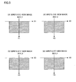
- a CPU 12p arranged in the image processing circuit 12 produces a bird's eye view image BEV_1 shown in Figure 5(A) based on the object scene image P_1 outputted from the camera C_1, and produces a bird's eye view image BEV_2 shown in Figure 5(B) based on the object scene image P_2 outputted from the camera C_2.
- the CPU 12p further produces a bird's eye view image BEV_3 shown in Figure 5(C) based on the object scene image P_3 outputted from the camera C_3, and a bird's eye view image BEV_4 shown in Figure 5(D) based on the object scene image P_4 outputted from the camera C_4.
- the bird's eye view image BEV_1 is equivalent to an image captured by a virtual camera looking down on the visual field VW_1 in a perpendicular direction
- the bird's eye view image BEV_2 is equivalent to an image captured by a virtual camera looking down on the visual field VW_2 in a perpendicular direction
- the bird's eye view image BEV_3 is equivalent to an image captured by a virtual camera looking down on the visual field VW_3 in a perpendicular direction
- the bird's eye view image BEV_4 is equivalent to an image captured by a virtual camera looking down on the visual field VW_4 in a perpendicular direction.
- the bird's eye view image BEV_1 has a bird's eye view coordinate system (X1, Y1)
- the bird's eye view image BEV_2 has a bird's eye view coordinate system (X2, Y2)
- the bird's eye view image BEV_3 has a bird's eye view coordinate system (X3, Y3)
- the bird's eye view image BEV_4 has a bird's eye view coordinate system (X4, Y4).
- the bird's eye views BEV_1 to BEV_4 are created based on an assumption that the water surface WS is an origin in the height direction. Furthermore, the created bird's eye views BEV_1 to BEV_4 are held in a work area W1 of a memory 12m.
- the CPU 12p respectively combines the bird's eye view images BEV_1 to BEV_4 through a coordinate transformation.
- the bird's eye view images BEV_2 to BEV_4 are rotated and/or moved by using the bird's eye view image BEV_1 as a reference.
- a whole-circumference bird's eye view image shown in Figure 6 is obtained in a work area W2 of the memory 12m.
- an overlapping area OL_12 is equivalent to an area in which the common visual field VW_12 is reproduced
- an overlapping area OL_23 is equivalent to an area in which the common visual field VW_23 is reproduced
- an overlapping area OL_34 is equivalent to an area in which the common visual field VW_34 is reproduced
- an overlapping area OL_41 is equivalent to an area in which the common visual field VW_41 is reproduced.
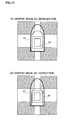
- the CPU 12p multiplexes a graphic image ST or SC that imitates an upper portion of the ship 100, onto a center of the whole-circumference bird's eye view image on the work area W2, cuts out one portion of an image in which the overlapping areas OL_12 to OL_41 are positioned at four corners, and then, outputs one portion of the cut-out image, i.e., the ship-maneuvering assisting image, toward the display device 16.
- the graphic image ST is equivalent to an image representing a whole of the aerially viewed ship 100, and is transparently (translucently) multiplexed onto the whole-circumference bird's eye view image.
- a contour of the graphic image ST is emphatically depicted by using a bold line.
- the graphic image SC is equivalent to an image representing one portion of the aerially viewed ship 100, and is non-transparently multiplexed onto the whole-circumference bird's eye view image from above the graphic image ST
- a size of one portion of the ship 100 represented by the graphic image GC is equivalent to a size of a cut-out surface obtained by cutting the ship 100 with the draft line DL.
- the bird's eye view images BEV_1 to BEV_4 are created according to the following procedure. It is noted that because each of the bird's eye view images BEV_1 to BEV_4 is created according to the same procedure, a procedure for creating the bird's eye view image BEV_3 is described as a representative example of the procedure for creating the bird's eye view images BEV_1 to BEV_4.
- the camera C_3 is placed, obliquely downward rearward, at an upper end center of a rear surface of the ship hull 102. If an angle of depression of the camera C_3 is assumed as " ⁇ d", an angle ⁇ shown in Figure 8 is equivalent to "180 degrees- ⁇ d". Furthermore, the angle ⁇ is defined in a range of 90 degrees ⁇ 180 degrees.
- Figure 9 shows a relationship among a camera coordinate system (X, Y, Z), a coordinate system (Xp, Yp) on an imaging surface S of the camera C_3, and a world coordinate system (Xw, Yw, Zw).
- the camera coordinate system (X, Y, Z) is a three-dimensional coordinate system having an X axis, Y axis, and Z axis as coordinate axes.
- the coordinate system (Xp, Yp) is a two-dimensional coordinate system having an Xp axis and Yp axis as coordinate axes.
- the world coordinate system (Xw, Yw, Zw) is a three-dimensional coordinate system having an Xw axis, Yw axis, and Zw axis as coordinate axes.
- an optical center of the camera C3 is an origin O.
- the Z axis is defined in an optical axis direction
- the X axis is defined in a direction orthogonal to the Z axis and parallel to the water surface WS
- the Y axis is defined in a direction orthogonal to the Z axis and X axis.
- a center of the imaging surface S is an origin O.
- the Xp axis is defined in a lateral direction of the imaging surface S and the Yp axis is defined in a vertical direction of the imaging surface S.
- an intersecting point between a perpendicular line passing through the origin O of the camera coordinate system (X, Y, Z) and the water surface WS is an origin Ow
- the Yw axis is defined in a direction vertical to the water surface WS
- the Xw axis is defined in a direction parallel to the X axis of the camera coordinate system (X, Y, Z)
- the Zw axis is defined in a direction orthogonal to the Xw axis and Yw axis.
- a distance from the Xw axis to the X axis is "h"
- an obtuse angle formed by the Zw axis and Z axis is equivalent to the above described angle ⁇ .
- Equation 3 shows a transformation equation for transformation between the coordinates (xp, yp) of the coordinate system (Xp, Yp) on the imaging surface S and the coordinates (xw, yw) of the two-dimensional water surface coordinate system (Xw, Zw).
- xp yp fxw h ⁇ sin ⁇ ⁇ + zwcos ⁇ ⁇ hcos ⁇ ⁇ - zwsin ⁇ ⁇ ⁇ f h ⁇ sin ⁇ ⁇ + zwcos ⁇ ⁇
- a bird's eye view coordinate system (X3, Y3) or coordinate system of the bird's eye view image BEV_3 shown in Figure 5(C) is defined.
- the bird's eye view coordinate system (X3, Y3) is a two-dimensional coordinate system having an X3 axis and Y3 axis as coordinate axes.
- coordinates in the bird's eye view coordinate system (X3, Y3) are written as (x3, y3)
- a position of each pixel forming the bird's eye view image BEV_3 is represented by coordinates (x3, y3).
- "x3" and "y3" respectively indicate an X3-axis component and a Y3-axis component in the bird's eye view coordinate system (X3, Y3).
- a projection from the two-dimensional coordinate system (Xw, Zw) that represents the water surface WS, onto the bird's eye view coordinate system (X3, Y3) is equivalent to a so-called parallel projection.
- a height of a virtual camera i.e., a height of a virtual view point
- Equation 4 a transformation equation for transformation between the coordinates (xw, zw) of the two-dimensional coordinate system (Xw, Zw) and the coordinates (x3, y3) of the bird's eye view coordinate system (X3, Y3) is represented by Equation 4 below.
- a height H of the virtual camera is previously determined.
- Equation 7 is equivalent to a transformation equation for transformation of the coordinates (xp, yp) of the coordinate system (Xp, Yp) on the imaging surface S into the coordinates (x3, y3) of the bird's eye view coordinate system (X3, Y3).
- the coordinates (xp, yp) of the coordinate system (Xp, Yp) on the imaging surface S represent the coordinates of the object scene image P_3 captured by the camera C_3. Therefore, the object scene image P_3 from the camera C_3 is transformed into the bird's eye view image BEV_3 by using Equation 7.
- the object scene image P_3 firstly undergoes an image process, such as a lens distortion correction, and is then transformed into the bird's eye view image BEV_3 using Equation 7.
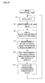
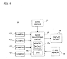
- the CPU 12p specifically executes a plurality of tasks in parallel, including an image processing task shown in Figure 10 . It is noted that a control program corresponding to these tasks is stored in a flash memory 14 (see Figure 1 ).
- the object scene images P_1 to P_4 are fetched from the cameras C_1 to C_4, respectively.
- the bird's eye view images BEV_1 to BEV_4 are created, and the created bird's eye view images BEV_1 to BEV_4 are secured in the work area W1.
- the bird's eye view images BEV_1 to BEV_4 created in the step S3 are combined together to create a whole-circumference bird's eye view image, and the created whole-circumference bird's eye view image is secured in the work area W2.
- a step S7 the translucent graphic image ST representing a whole of the aerially viewed ship 100 is multiplexed onto the whole-circumference bird's eye view image secured in the work area W2.
- the graphic image SG representing one portion of the aerially viewed ship 100 is additionally multiplexed onto the whole-circumference bird's eye view image secured in the work area W2.
- a step S11 one portion of the whole-circumference bird's eye view image onto which the graphic images ST and SG are multiplexed is cut out from the work area W2, and this cut-out image is outputted toward the display device 16 as the ship-maneuvering assisting image.
- each of the cameras C_1 to C_4 is arranged in a downward attitude on the side surfaces of the ship hull 102, and in this attitude, captures the surroundings of the ship 100.
- the CPU 12p creates a whole-circumference bird's eye view image (surrounding image) that represents in an aerially viewed manner the surroundings of the ship 100, based on the output of the cameras C_1 to C_4 (S3 to S5). Furthermore, the CPU 12p transparently multiplexes the graphic image ST that represents at least the extension of the aerially viewed ship 100, onto the whole-circumference bird's eye view image (S7).
- the graphic image ST that represents at least the extension of the aerially viewed ship 100 is multiplexed onto the whole-circumference bird's eye view image that represents in an aerially viewed manner the surroundings of the ship 100, the positional relationship between the ship 100 and its surroundings becomes clear. Furthermore, when the graphic image ST is transparently multiplexed, the blind spot in the surroundings of the ship 100 is decreased. As a result, a maneuverability of the ship 100 improves.
- attitude information about the cameras C_1 to C_4 (specifically, the definition of the XYZ axes shown in Figure 9 ) that is referenced for creating the bird's eye view images BEV_1 to BEV_4 is fixed regardless of rocking of the ship hull 102 (i.e., a change in inclination and/or altitude of the ship hull 102).
- a shape of the graphic image SC is also fixed.
- a gyro sensor 20 for sensing the rocking of the ship hull 102 may be optionally added as shown in Figure 11 so that the attitude information of the cameras C_1 to C_4 and the shape of the graphic image SC are corrected based on output of the gyro sensor 20.
- the CPU 12p In order to correct the attitude information of the cameras C_1 to C_4 and the shape of the graphic image SC as described above, the CPU 12p further executes a graphic-image correcting task shown in Figure 14 .
- a step 521 the inclination and altitude of the ship hull 102 are calculated based on the output of the gyro sensor 20.
- a step S23 the definition of the XYZ axes allocated to each of the cameras C_1 to C_4 is corrected with reference to the inclination and the altitude calculated in the step S21.
- the corrected XYZ axes are reflected in the process in the step S3 shown in Figure 10 , and as a result, the deviation among the bird's eye view images BEV_1 to BEV_4 is prevented.
- a deviation amount from a reference value of the inclination of the ship hull 102 is calculated as " ⁇ SW”
- a deviation amount from a reference value of the altitude of the ship hull 102 is calculated as "AHT”.
- a step S29 based on the calculated deviation amounts ⁇ SW and ⁇ HT, it is determined whether or not the rocking of the ship hull 102 is large.
- the deviation amount ⁇ SW exceeds a threshold value TH1 or the deviation amount ⁇ HT exceeds a threshold value TH2, it is determined that the rocking is large, and when the deviation amount ⁇ SW is equal to less than the threshold value TH1 or the deviation amount ⁇ HT is equal or less than the threshold value TH2, it is determined that the rocking is small.
- the shape of the graphic image SC is initialized in a step S33, and the process returns to the step S21. If YES is determined in the step S29, the process proceeds to a step S31 in which the shape of the graphic image SC is corrected in consideration of the rocking of the ship hull 102.
- the corrected shape of the graphic image SC is equivalent to the cross-sectional shape obtained by cutting the ship hull 102 with the draft line DL of the rocked ship hull 102. Thereby, the deviation between the shape of the graphic image SC and the cross-sectional shape of the ship hull 102 at the draft line DL is prevented
- the process in the step S31 is reflected in the process in the step S9 shown in Figure 10 . Upon completion of the process in the step S3 1, the process returns to the step S21.
- the graphic image ST representing a whole of the aerially viewed ship 100 is transparently multiplexed onto the whole-circumference bird's eye view image (see Figure 7 ).
- an outline image SL that represents the extension (outline) of the aerially viewed ship 100 may optionally be multiplexed onto the whole-circumference bird's eye view image according to a procedure shown in Fig 15 .
- the CPU 12p execute the process in the step S41 shown in Figure 16 (process for multiplexing the outline image SL onto the whole-circumference bird's eye view image) instead of the process in the step S7 shown in Figure 10 .
- the whole-circumference bird's eye view image obtained by aerially viewing a whole circumference of the ship 100 is displayed.
- it may be optionally configured so that only one portion of the bird's eye view image is displayed and the one portion of the bird's eye view image that should be displayed is updated based on a moving direction, a moving speed, the attitude, etc., of the ship 100.
- the ship 100 is assumed as a moving object, however, an aircraft or a large dump truck may also be assumed as the moving object
- a plurality of cameras are installed in an obliquely downward attitude, under a body of the aircraft or under the wings.
- a graphic image or an outline image representing a whole of the aerially viewed aircraft is transparently multiplexed onto a bird's eye view image based on output of the plurality of cameras. Thereby, a maneuverability during take-off and landing is improved.
- a plurality of cameras are installed in an obliquely downward attitude between a vehicle main body and tires.
- a graphic image or an outline image representing a whole of the aerially viewed dump truck is transparently multiplexed onto a bird's eye view image based on output of the plurality of cameras.
- the coordinate transformation for producing a bird's eye view image from a photographed image which is described in the embodiment, is generally called a perspective projection transformation.
- the bird's eye view image may also be optionally produced from the photographed image through a well-known planer projection transformation.
- planer projection transformation a homography matrix (coordinate transformation matrix) for transforming a coordinate value of each pixel on the photographed image into a coordinate value of each pixel on the bird's eye view image is evaluated at a stage of a camera calibrating process.
- a method of evaluating the homography matrix is well known.
- the photographed image may be transformed into the bird's eye view image based on the homography matrix. In either way, the photographed image is transformed into the bird's eye view image by projecting the photographed image on the bird's eye view image.
Landscapes
- Engineering & Computer Science (AREA)
- Radar, Positioning & Navigation (AREA)
- Remote Sensing (AREA)
- Chemical & Material Sciences (AREA)
- Combustion & Propulsion (AREA)
- Mechanical Engineering (AREA)
- Ocean & Marine Engineering (AREA)
- Closed-Circuit Television Systems (AREA)
- Traffic Control Systems (AREA)
Applications Claiming Priority (1)
| Application Number | Priority Date | Filing Date | Title |
|---|---|---|---|
| JP2008262451A JP2010093605A (ja) | 2008-10-09 | 2008-10-09 | 操縦支援装置 |
Publications (1)
| Publication Number | Publication Date |
|---|---|
| EP2174834A2 true EP2174834A2 (de) | 2010-04-14 |
Family
ID=41510821
Family Applications (1)
| Application Number | Title | Priority Date | Filing Date |
|---|---|---|---|
| EP09012775A Withdrawn EP2174834A2 (de) | 2008-10-09 | 2009-10-08 | Mänovrierhilfsvorrichtung |
Country Status (3)
| Country | Link |
|---|---|
| US (1) | US20100092042A1 (de) |
| EP (1) | EP2174834A2 (de) |
| JP (1) | JP2010093605A (de) |
Cited By (2)
| Publication number | Priority date | Publication date | Assignee | Title |
|---|---|---|---|---|
| CN103733613A (zh) * | 2011-07-26 | 2014-04-16 | 爱信精机株式会社 | 车辆周边监视系统 |
| EP4040377A3 (de) * | 2021-02-04 | 2022-08-17 | Honeywell International Inc. | Anzeigesysteme und verfahren |
Families Citing this family (23)
| Publication number | Priority date | Publication date | Assignee | Title |
|---|---|---|---|---|
| TWI392366B (zh) * | 2009-12-31 | 2013-04-01 | Ind Tech Res Inst | 全周鳥瞰影像距離介面產生方法與系統 |
| JP5479956B2 (ja) * | 2010-03-10 | 2014-04-23 | クラリオン株式会社 | 車両用周囲監視装置 |
| JP5124671B2 (ja) * | 2011-06-07 | 2013-01-23 | 株式会社小松製作所 | 作業車両の周辺監視装置 |
| JP2012252675A (ja) * | 2011-06-07 | 2012-12-20 | Komatsu Ltd | ダンプトラック |
| JP5575703B2 (ja) * | 2011-06-07 | 2014-08-20 | 株式会社小松製作所 | ダンプトラックの積載量表示装置 |
| JP5597596B2 (ja) * | 2011-06-07 | 2014-10-01 | 株式会社小松製作所 | 作業車両の周辺監視装置 |
| JP5781978B2 (ja) * | 2012-05-22 | 2015-09-24 | 株式会社小松製作所 | ダンプトラック |
| JP5629740B2 (ja) * | 2012-09-21 | 2014-11-26 | 株式会社小松製作所 | 作業車両用周辺監視システム及び作業車両 |
| JP5643272B2 (ja) * | 2012-09-21 | 2014-12-17 | 株式会社小松製作所 | 作業車両用周辺監視システム及び作業車両 |
| JP5823553B2 (ja) * | 2014-03-10 | 2015-11-25 | 株式会社小松製作所 | 作業車両用周辺監視システム及び作業車両 |
| JP5964353B2 (ja) * | 2014-06-04 | 2016-08-03 | 株式会社小松製作所 | ダンプトラック |
| JP6012680B2 (ja) * | 2014-09-02 | 2016-10-25 | 株式会社小松製作所 | ダンプトラック |
| DK179246B1 (en) * | 2016-03-31 | 2018-03-05 | Ap Moeller Maersk As | Container ship |
| US11733699B2 (en) * | 2017-06-16 | 2023-08-22 | FLIR Belgium BVBA | Ultrasonic perimeter ranging sensor systems and methods |
| WO2019093416A1 (ja) * | 2017-11-08 | 2019-05-16 | Molエンジニアリング株式会社 | 船舶の航行支援システム |
| JP2019151304A (ja) * | 2018-03-06 | 2019-09-12 | アイシン精機株式会社 | 周辺監視装置 |
| JP2019186869A (ja) * | 2018-04-17 | 2019-10-24 | 株式会社ザクティ | 船舶の撮影装置およびその校正方法 |
| JP7347936B2 (ja) * | 2019-02-25 | 2023-09-20 | ヤマハ発動機株式会社 | 船舶の撮影装置、および該撮影装置を有する船舶 |
| JP7317531B2 (ja) | 2019-03-14 | 2023-07-31 | ヤマハ発動機株式会社 | 船舶の撮影システムおよびそれを備えた船舶、ならびに船舶の撮影システムの較正方法 |
| JP7232089B2 (ja) * | 2019-03-19 | 2023-03-02 | ヤマハ発動機株式会社 | 船舶用の表示装置、船舶および船舶用の画像表示方法 |
| JP2020161886A (ja) * | 2019-03-25 | 2020-10-01 | 株式会社ザクティ | 船舶の周辺確認システム |
| JP2023001715A (ja) * | 2021-06-21 | 2023-01-06 | 本田技研工業株式会社 | 物体検出装置 |
| CN114005302B (zh) * | 2021-10-15 | 2023-07-07 | 中远海运科技股份有限公司 | 沿海船舶空船指数生成方法及系统 |
Citations (1)
| Publication number | Priority date | Publication date | Assignee | Title |
|---|---|---|---|---|
| JP2008262451A (ja) | 2007-04-13 | 2008-10-30 | Matsushita Electric Ind Co Ltd | メモリ電源管理装置及びメモリ電源管理方法 |
Family Cites Families (5)
| Publication number | Priority date | Publication date | Assignee | Title |
|---|---|---|---|---|
| JP4114292B2 (ja) * | 1998-12-03 | 2008-07-09 | アイシン・エィ・ダブリュ株式会社 | 運転支援装置 |
| EP1158804A3 (de) * | 2000-05-24 | 2003-12-17 | Matsushita Electric Industrial Co., Ltd. | Wiedergabevorrichtung zur Erzeugung einer Bildeinzeige |
| JP4254887B2 (ja) * | 2006-07-06 | 2009-04-15 | 日産自動車株式会社 | 車両用画像表示システム |
| JP2008187566A (ja) * | 2007-01-31 | 2008-08-14 | Sanyo Electric Co Ltd | カメラ校正装置及び方法並びに車両 |
| JP2008187564A (ja) * | 2007-01-31 | 2008-08-14 | Sanyo Electric Co Ltd | カメラ校正装置及び方法並びに車両 |
-
2008
- 2008-10-09 JP JP2008262451A patent/JP2010093605A/ja not_active Withdrawn
-
2009
- 2009-10-08 US US12/576,107 patent/US20100092042A1/en not_active Abandoned
- 2009-10-08 EP EP09012775A patent/EP2174834A2/de not_active Withdrawn
Patent Citations (1)
| Publication number | Priority date | Publication date | Assignee | Title |
|---|---|---|---|---|
| JP2008262451A (ja) | 2007-04-13 | 2008-10-30 | Matsushita Electric Ind Co Ltd | メモリ電源管理装置及びメモリ電源管理方法 |
Cited By (4)
| Publication number | Priority date | Publication date | Assignee | Title |
|---|---|---|---|---|
| CN103733613A (zh) * | 2011-07-26 | 2014-04-16 | 爱信精机株式会社 | 车辆周边监视系统 |
| US9050931B2 (en) | 2011-07-26 | 2015-06-09 | Aisin Seiki Kabushiki Kaisha | Vehicle periphery monitoring system |
| EP4040377A3 (de) * | 2021-02-04 | 2022-08-17 | Honeywell International Inc. | Anzeigesysteme und verfahren |
| US12033528B2 (en) | 2021-02-04 | 2024-07-09 | Honeywell International Inc. | Display systems and methods |
Also Published As
| Publication number | Publication date |
|---|---|
| US20100092042A1 (en) | 2010-04-15 |
| JP2010093605A (ja) | 2010-04-22 |
Similar Documents
| Publication | Publication Date | Title |
|---|---|---|
| EP2174834A2 (de) | Mänovrierhilfsvorrichtung | |
| EP2196388A1 (de) | Manöverunterstüzungsvorrichtung | |
| US7423553B2 (en) | Image display apparatus, image display method, measurement apparatus, measurement method, information processing method, information processing apparatus, and identification method | |
| US8295644B2 (en) | Birds eye view virtual imaging for real time composited wide field of view | |
| CN105453558B (zh) | 车辆周边监视装置 | |
| US20110001819A1 (en) | Image Processing Apparatus | |
| US20060202984A1 (en) | Driving support system | |
| US8169309B2 (en) | Image processing apparatus, driving support system, and image processing method | |
| JP2009151524A (ja) | 画像表示方法および画像表示装置 | |
| US20140118551A1 (en) | Vehicle surrounding-area monitoring apparatus | |
| JP4193886B2 (ja) | 画像表示装置 | |
| EP3690799B1 (de) | Detektion von fahrzeugspurmarkierung und anderer objekte unter verwendung von seitlichen fischaugenkameras und dreifacher entzerrung | |
| US20100149333A1 (en) | Obstacle sensing apparatus | |
| JP6471522B2 (ja) | カメラパラメータ調整装置 | |
| JP5178454B2 (ja) | 車両周囲監視装置及び車両周囲監視方法 | |
| JP2020150459A (ja) | 船舶の撮影システムおよびそれを備えた船舶、ならびに船舶の撮影システムの較正方法 | |
| JP4248570B2 (ja) | 画像処理装置並びに視界支援装置及び方法 | |
| JP2008143701A (ja) | 産業車両の視界改善システム及び方法 | |
| US20220222947A1 (en) | Method for generating an image of vehicle surroundings, and apparatus for generating an image of vehicle surroundings | |
| EP2330581A1 (de) | Lenkhilfevorrichtung | |
| JP5861871B2 (ja) | 俯瞰画像提示装置 | |
| JP5049304B2 (ja) | 車両の周辺を画像表示するための装置 | |
| JP2019186597A (ja) | 移動体の周辺確認システム | |
| JP4706896B2 (ja) | 広角画像の補正方法及び車両の周辺監視システム | |
| US12337760B2 (en) | Display control device and display control method |
Legal Events
| Date | Code | Title | Description |
|---|---|---|---|
| PUAI | Public reference made under article 153(3) epc to a published international application that has entered the european phase |
Free format text: ORIGINAL CODE: 0009012 |
|
| AK | Designated contracting states |
Kind code of ref document: A2 Designated state(s): AT BE BG CH CY CZ DE DK EE ES FI FR GB GR HR HU IE IS IT LI LT LU LV MC MK MT NL NO PL PT RO SE SI SK SM TR |
|
| AX | Request for extension of the european patent |
Extension state: AL BA RS |
|
| STAA | Information on the status of an ep patent application or granted ep patent |
Free format text: STATUS: THE APPLICATION HAS BEEN WITHDRAWN |
|
| 18W | Application withdrawn |
Effective date: 20120405 |