EP2174871B1 - Verfahren und Vorrichtung zum Verpacken von Matratzen in einer Verpackung aus mehreren Wicklungen, die ineinander angeordnet sind - Google Patents
Verfahren und Vorrichtung zum Verpacken von Matratzen in einer Verpackung aus mehreren Wicklungen, die ineinander angeordnet sind Download PDFInfo
- Publication number
- EP2174871B1 EP2174871B1 EP09172295A EP09172295A EP2174871B1 EP 2174871 B1 EP2174871 B1 EP 2174871B1 EP 09172295 A EP09172295 A EP 09172295A EP 09172295 A EP09172295 A EP 09172295A EP 2174871 B1 EP2174871 B1 EP 2174871B1
- Authority
- EP
- European Patent Office
- Prior art keywords
- mattress
- sheet
- conveyor
- resting surface
- heat
- Prior art date
- Legal status (The legal status is an assumption and is not a legal conclusion. Google has not performed a legal analysis and makes no representation as to the accuracy of the status listed.)
- Not-in-force
Links
- 238000004806 packaging method and process Methods 0.000 title claims abstract description 14
- 238000000034 method Methods 0.000 title claims abstract description 10
- 238000007789 sealing Methods 0.000 claims description 39
- 230000000284 resting effect Effects 0.000 claims description 36
- 230000015572 biosynthetic process Effects 0.000 claims description 15
- 238000005520 cutting process Methods 0.000 claims description 13
- 230000033001 locomotion Effects 0.000 claims description 11
- 230000002441 reversible effect Effects 0.000 claims description 6
- 230000005540 biological transmission Effects 0.000 claims description 4
- 239000000463 material Substances 0.000 abstract description 4
- 230000004913 activation Effects 0.000 description 5
- 230000007246 mechanism Effects 0.000 description 5
- 230000003213 activating effect Effects 0.000 description 2
- 230000000712 assembly Effects 0.000 description 2
- 238000000429 assembly Methods 0.000 description 2
- 239000000428 dust Substances 0.000 description 2
- 238000005096 rolling process Methods 0.000 description 2
- 230000007480 spreading Effects 0.000 description 2
- 238000003892 spreading Methods 0.000 description 2
- 238000000605 extraction Methods 0.000 description 1
- 239000012775 heat-sealing material Substances 0.000 description 1
- 238000003780 insertion Methods 0.000 description 1
- 230000037431 insertion Effects 0.000 description 1
- 230000000670 limiting effect Effects 0.000 description 1
- 238000012986 modification Methods 0.000 description 1
- 230000004048 modification Effects 0.000 description 1
- 238000012858 packaging process Methods 0.000 description 1
- 230000002829 reductive effect Effects 0.000 description 1
- 230000000717 retained effect Effects 0.000 description 1
- 238000000926 separation method Methods 0.000 description 1
- 238000003860 storage Methods 0.000 description 1
Images







Classifications
-
- B—PERFORMING OPERATIONS; TRANSPORTING
- B65—CONVEYING; PACKING; STORING; HANDLING THIN OR FILAMENTARY MATERIAL
- B65B—MACHINES, APPARATUS OR DEVICES FOR, OR METHODS OF, PACKAGING ARTICLES OR MATERIALS; UNPACKING
- B65B11/00—Wrapping, e.g. partially or wholly enclosing, articles or quantities of material, in strips, sheets or blanks, of flexible material
- B65B11/58—Applying two or more wrappers, e.g. in succession
-
- B—PERFORMING OPERATIONS; TRANSPORTING
- B65—CONVEYING; PACKING; STORING; HANDLING THIN OR FILAMENTARY MATERIAL
- B65B—MACHINES, APPARATUS OR DEVICES FOR, OR METHODS OF, PACKAGING ARTICLES OR MATERIALS; UNPACKING
- B65B11/00—Wrapping, e.g. partially or wholly enclosing, articles or quantities of material, in strips, sheets or blanks, of flexible material
- B65B11/06—Wrapping articles, or quantities of material, by conveying wrapper and contents in common defined paths
- B65B11/08—Wrapping articles, or quantities of material, by conveying wrapper and contents in common defined paths in a single straight path
- B65B11/10—Wrapping articles, or quantities of material, by conveying wrapper and contents in common defined paths in a single straight path to fold the wrappers in tubular form about contents
- B65B11/12—Wrapping articles, or quantities of material, by conveying wrapper and contents in common defined paths in a single straight path to fold the wrappers in tubular form about contents and then to form closing folds of similar form at opposite ends of the tube
-
- B—PERFORMING OPERATIONS; TRANSPORTING
- B65—CONVEYING; PACKING; STORING; HANDLING THIN OR FILAMENTARY MATERIAL
- B65B—MACHINES, APPARATUS OR DEVICES FOR, OR METHODS OF, PACKAGING ARTICLES OR MATERIALS; UNPACKING
- B65B63/00—Auxiliary devices, not otherwise provided for, for operating on articles or materials to be packaged
- B65B63/02—Auxiliary devices, not otherwise provided for, for operating on articles or materials to be packaged for compressing or compacting articles or materials prior to wrapping or insertion in containers or receptacles
Definitions
- the present invention relates to a method and an apparatus for packaging a mattress in a package composed of multiple wrappings arranged one inside the other.
- Mattresses in order to be protected against dust and during the handling that they undergo during sorting and transport operations, are currently contained in a package consisting of a sheet of plastic material that is closed hermetically and is usually transparent for making the characteristics of the contained product visible.
- the package due to tearing caused by breakage or due to the dirt and dust that has deposited thereon during storage, often is scarcely acceptable to buyers and does not make the informational and advertising lettering, often provided on the outside of the package, fully visible.
- the aim of the present invention is to devise a method for packaging a mattress in a package composed of multiple wrappings arranged one over the other around the mattress.
- an object of the present invention is to provide a method for packaging a mattress in a package composed of two wrappings arranged one inside the other around the mattress, which consist of material in sheet form taken from at least one respective reel.
- Another object of the present invention is to provide an apparatus for performing the method described above.
- an apparatus for packaging a mattress in a package characterized in that it comprises a first conveyor for the advancement of the mattress and a second conveyor for receiving and transferring the mattress, said conveyors forming a resting surface and being mutually separated by an opening, means for actuating said conveyors to transfer said mattress from one conveyor to the other by bridging said opening, a structure for supporting a reel of a sheet that can be heat-sealed above said conveyors, means for engaging an element for fixing the end of the sheet unwound from said reel, means for actuating and guiding said fixing element through said opening between a lower position, which lies below said resting surface and in which said sheet is stretched through said opening, and an upper position, which lies above said resting surface, up to such a height as to allow the passage of a mattress between said resting surface and said fixing element, heat-sealing means arranged above said resting surface, said means for actuating the fixing element, for heat-sealing and cutting and moving the mattress being functionally coordinated so
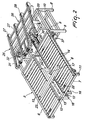
- the reference numeral 1 generally designates an apparatus, which can be assumed to be composed of two working assemblies 2 and 3, designed to move a mattress M, between which a third working assembly 4 is arranged which is designed to close the two wrappings that compose the package.
- the first assembly 2 shown in greater detail in Figures 2-4 , constitutes an advancement conveyor (designated hereinafter by the same reference numeral 2 for the sake of convenience) and comprises a rectangular frame 5 that is composed of two lateral longitudinal members 6, which are connected at their opposite ends by two cross-members 7.
- the frame 5 rests on the ground, at one end, by means of uprights 8, which are connected by longitudinal stringers 9 and transverse stringers 10.
- the reference numeral 12 designates two bars, which are parallel to the longitudinal members 6 and whose opposite ends are fixed to the cross-member 7 and, by means of raised portions 12a, to the stringer 10.
- Two series of parallel rollers 13 and 14 are pivoted in the bars 12 and in the longitudinal members 6 and form respective rolling surfaces, which allow the movement of the mattress during the formation of the package.
- An elongated opening 15 remains between the bars 12 and below them there are two beams 16, which, at one end, hang down below the cross-member 7 and, at the opposite portion, rest and are fixed on the transverse stringers 10.
- the beams 16 support sliding guides 16a for a slider 17 (see Figures 3 , 4 ), which is connected to a driving chain 18, which is closed in a loop around a respective driving gear 19 and driven gear 20, which are supported so that they can rotate on brackets 21 that are fixed on the beams 16.
- the driving gear 19 is actuated by a reversible gearmotor 21a, which is coupled by means of a flange below the cross-member 7.
- a pusher 22 is fixed on the slider 17 and forms, with the rolling surfaces consisting of the rollers 13, 14, the advancement conveyor 2, which, by means of the closure assembly 4, transfers the mattress toward the working assembly 3, as will become better apparent in the further description.
- the pusher 22 consists in a bar 23, which is parallel to the rollers 13, 14 and is fixed to an L-shaped arm 24, which rises from the slider 17 on which it is fixed.
- the arm 24 moves along the opening 15, while the bar 23 of the pusher 22, by moving above the rollers 13, 14, can push the mattress M to be packaged toward the assembly 3 once said mattress has been deposited on the rollers by a feeder conveyor 25.
- the feeder conveyor 25 can be of any type.
- it advantageously consists of a frame 26 on which multiple parallel belts 27 are mounted, their upper portions being mutually coplanar so as to form a surface for conveying the mattress.
- the belts 27 are closed in a loop on respective guiding pulleys 28 and driving pulleys 29, of which the driving pulleys 29 are keyed on a shaft 30 that is supported rotatably by the frame 26.
- the shaft 30 is motorized, by means of a transmission 31, by a gearmotor 32 mounted below the frame 26.
- the conveyor 25 is fixed obliquely with respect to the frame 25 (see Figure 2 ) by brackets 33, and its length is such as to overlap the driving pulleys 29 on the rollers 13, 14, so as to be able to unload the mattress M in front of the bar 23 of the pusher 22, which, due to the L-shaped configuration of the arm 24, can return below the belts 27.
- the advancement conveyor 2 described so far is completed by a further motor drive, which is designed so as to allow the free rotation of the rollers 13, 14 when the pusher 22 pushes the mattress M in the advancement direction A from the initial position (i.e., for receiving the mattress M from the feeder conveyor 25) toward the assembly 3 by way of suitable means.
- a further motor drive which is designed so as to allow the free rotation of the rollers 13, 14 when the pusher 22 pushes the mattress M in the advancement direction A from the initial position (i.e., for receiving the mattress M from the feeder conveyor 25) toward the assembly 3 by way of suitable means.
- the rollers 13, 14 are actuated positively, they entrain the mattress that arrives from the assembly 3 in the direction B for return of the pusher 22 toward the starting position.
- Said motor drive means consist of two shafts 34, 35 (see Figures 2 , 4 ), which are perpendicular to the rollers 13, 14 and can rotate within supports that are fixed below the lateral longitudinal members 6 and are actuated by respective gearmotors 36, 37 that are fixed to said longitudinal members by means of flanges.
- gearmotors 36, 37 For transmitting the motion from the gearmotors 36, 37 to the rollers 13, 14 belts 38 are provided, which are closed in a loop around the shafts 34, 35 and around pulleys (not visible in the drawings) that are keyed to the ends of the rollers.
- Each mattress M deposited on the advancement conveyor 2 is transferred onto the assembly 3, which in combination with the working assemble 4 stretches and wraps around the mattress M a first sheet 38 of plastic material, which is unwound from a respective reel 39 (see Figure 10 ) and is wider than the mattress.
- the mattress is again returned to the advancement conveyor 2, so to be able to start a second identical packaging operation for wrapping around the mattress a second sheet that is separate from the first one.
- the assembly 3 (see Figures 5 , 6 , 8 ) consists of a frame 40, which is composed of two lateral longitudinal members 41 connected by cross-members 42. Two rollers 43, 44 are supported rotatably at the opposite ends of the longitudinal members 41, and belts 45 which are mutually parallel and spaced are closed in a loop around said rollers.
- the upper portions of the belts are coplanar and slightly raised at the opposite ends by means of rollers 46, which are keyed to respective shafts 47 supported within the longitudinal members 41 proximately to the rollers 43, 44.
- the upper portions of the belts 45 are in sliding contact with the top of a slab 48, which is fixed on the frame 40 between the rollers 43, 44 and the lateral longitudinal members 41.
- roller 43 The function of the roller 43 is to drive the belts 45.
- a gearmotor 49 which is flanged to a longitudinal member 41 and is of the reversible type in order to actuate the belts in both directions A and B of sliding on the slab 48.
- the assembly 3 acts like a conveyor, which after receiving the mattress from the advancement conveyor 2 and after the formation of the first wrapping, transfers it onto the conveyor 2 in order to start the formation of the second wrapping.
- the opposite ends of the longitudinal members 41 rest on, and are fixed to, two cross-members 50, 50a.
- the cross-member 50 extends between two posts 52, which are lateral with respect to the longitudinal members 41 and are mutually connected at the top by a cross-member 53, which lies in a bridge-like arrangement above the belts 45.
- the opposite ends of the cross-member 50a are fixed between the two columns 54 of a bridge-like frame 55 which is arranged between the assemblies 2 and 3 and constitutes the supporting structure of the closure assembly 4.
- the structure 55 is strengthened by a beam 51 that extends between the tops of the columns 54 and is connected to the cross-member 53 by two upper beams 56 and two lower beams 57.
- Two bearings 57a are fixed to each lower beam 57 in order to support two shafts 58, which are parallel and perpendicular to the belts 45.
- Corresponding sprockets 59 are keyed to the opposite ends of the two shafts 58 and mesh with a transmission chain (not visible in the drawing because it is covered by a housing 59a), which is wound around them and constrains the rotation of the shafts 58 in the same direction.
- two pinions 60 are keyed to each shaft 58 and mesh with respective vertical racks 61, which are fixed to vertical strips 63 that are kept guided between pairs of free rollers 62, which are mounted below the cross-members 57 and to the lower end of which a panel 64 is fixed whose faces are flat and parallel to the underlying slab 48 and which forms with said slab a compartment for accommodating the mattress M.
- the opposite ends of two strips 64a are jointly connected above the cross-members 57 and two fluid-operated jacks 65 are supported between said strips, their stems being coupled to the panel 64, and actuate the lifting and lowering of the panel 64 with respect to the slab 48.
- the panel 64 acts as a presser designed to reduce the thickness of the mattress before the sheet 38 is closed so as to form the wrapping.
- Two transverse rails 66 are fixed below the lateral longitudinal members 41 of the frame 40, and two supporting carriages 67, for heat-sealing elements adapted to close hermetically at its sides the package that will be formed, can be arranged on said rails, one for each side of the frame 40 and so as to be mutually opposite.
- Each carriage 67 is composed of two elements 68, which are substantially C-shaped and are mutually connected by strips 69.
- Each one of the elements 68 comprises a lower arm which is provided with wheels 70 for the gliding of the carriage 67 on the rails 66 and an upper arm which protrudes in a cantilever fashion above the slab 48 and supports a fluid-operated jack 71.
- each carriage extends downward and a heat-sealing bar 72 hangs down from them, parallel to the belts 45, a bar 73 being arranged opposite the heat-sealing bar 72 in a lower region, fixed to brackets 73a of the carriage and acting as a contrast member for the heat-sealing bar to perform the heat-seals for the lateral closure of the wrapping.
- said jacks are provided with adapted mechanisms that constrain the stems of the pair of jacks 71 mounted on each carriage 67 so as to follow identical paths.
- these mechanisms are not shown, since they are assumed to be fully traditional, consisting of, for example, racks which are formed in the stems of the jacks and mesh with pinions that are keyed to the ends of a shaft 74a which can rotate in supports that are jointly connected to the upper arms of the carriage.
- the mechanisms are similar to what is described above with respect to the elements 58, 60, 61 by means of which the vertical movements of the plate 64 are restrained kinematically.
- the advancement conveyor 2 and the receiving and transfer conveyor 3 are mutually spaced so as to form, between the roller 44 and the rollers 13, 14, an opening 75 (see Figures 1 , 10-14 ) at which the structure 55 of the third operating assembly 4 is arranged which comprises the means that stretch the packaging sheet which is ready to be wrapped in a loop around the mattress and then complete its hermetic sealing in combination with the lateral heat-sealing performed between the heat-sealing bars 72, 73.
- Said means consist of a heat-sealing bar 76 and a corresponding contrast bar 77, which extend transversely between the columns 54 of the structure 55.
- the heat-sealing bar 76 is of the type that produces two parallel heat-sealing lines and a separation cut between the two heat-sealing lines.
- the heat-sealing bar 76 hangs down, at its opposite ends, from the stems of two jacks 78, which are accommodated vertically in the columns 54 and of which only the cylinders are visible in the figures.
- the stems of the jacks 78 are mutually coupled by a mechanism that is identical to the one described earlier with respect to the stems of the jacks 71 that move the lateral bars 72.
- this mechanism it is possible to recognize in Figure 7 the longitudinal shaft 79 and the pinions 80, which mesh with the respective racks provided in the stems of the jacks 78 and are concealed within the columns 54.
- Two vertical guides 81 for a slider 82 that can be actuated vertically by means of a pair of fluid-operated jacks 83 mounted on the beam 51, are fixed to the opposed faces of the columns 54 and proximately to the heat-sealing bar 76.
- the slider 82 is composed of a strip 84, which is provided at its ends with brackets 85, which support a roller 86 and are provided with sliders 87 that slidingly engage the guides 81.
- the roller 86 can be lowered onto a further roller 88, which is supported so that it can rotate within the columns 54 at the height of the belts 45 and rollers 13, 14 and at the opening 75, so as to provide an additional support for the mattress M during its transfer from the working assembly 2 to the other assembly 3.
- the roller 86 in the raised position, forms together with the roller 88 the inlet to the compartment for accommodating the mattress between the straps 45 and the plate 64.
- Two profiles 89 are arranged adjacent to the guides 81 and form vertical channels in which the opposite ends of a cylindrical rod 90 are engaged slidingly (see Figures 1 , 7 , 10-14 ), and the end edge of the sheet 38 of heat-sealing material designed to form the package and taken from the reel 39 is fixed to said rod so that it rotates jointly with said rod.
- the reel 39 rests so as to roll on two counter-rotating rollers 91, which are supported by shoulders 92 that rise from the top of the columns 54.
- One of the rollers 91 is actuated by a gearmotor 93 of the reversible type, which is mounted on a shoulder 92 and is adapted to control the unwinding of the sheet 38 from the reel 39.
- a gearmotor 93 of the reversible type
- the apparatus described so far is completed by a devise for allowing the movement of the rod 90 from a height that lies below the resting surface of the mattress M on the advancement conveyor 2 and on the receiving and transfer conveyor 3, i.e., the plane formed by the rollers 13, 14 and by the belts 45, to a level that lies above the resting surface by a height that is at least greater than the thickness of the mattress.
- Said device comprises a pair of belts 94, each of which is closed vertically in a loop around two pulleys 95, 96, the upper ones 95 of which can rotate on the internal faces of the columns 54 and the lower ones 96 of which are keyed to the ends of a shaft 97 that is supported rotationally in brackets 98 fixed in a cantilever fashion to a base 99 of the structure 55.
- the belts 94 are moved by a reversible gearmotor 100, which is mounted on the base 99 and transmits motion to the shaft 97 by means of a transmission 101.
- a vertical guide 102 for the sliding of a sliding block 103 is arranged to the side of each belt 94 and said sliding block is fixed in a cantilever fashion to a portion of the respective belt so that it can perform upward and downward strokes.
- a fluid-operated actuator 104 is incorporated in each sliding block 103 and is provided with stems 105 to which an engagement element is jointly connected which consists of a fork 106 (see Figures 1 , 7 ), which protrudes horizontally toward the guide 81. By activation of the actuators 104, the forks 106 can engage and disengage the ends of the fixing rod 90 of the sheet when it lies below the plane of the rollers 13, 14.
- a portion of the sheet 38 is unwound from the reel 39 and its end is fixed to the rod 90.
- the rod is then lowered below the plane of the rollers 13, 14 and engaged at the opposite ends by the forks 106 actuated by the actuators 104, so that the unwound portion of sheet is stretched through the opening 75.
- a guiding roller 107 which spreads the sheet on a vertical plane that passes through the channels 89 (see Figure 10 ).
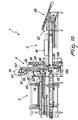
- the pusher 22 After unloading onto the rollers 13, 14 the mattress M to be packaged by means of the feeder 25, the pusher 22 is activated and, from its position below the feeder 25, pushes the mattress M in the direction A against the sheet 38, forcing it between the plane of the belts 45 and the plate 64 of the presser (see Figure 11 ).
- the transverse heat-sealing unit 76, 77 is actuated and joins the superimposed flaps of the sheet along two parallel and adjacent heat-sealing lines and cuts them along a line that is intermediate with respect to the heat-sealing lines, causing at once the formation of a first wrapping (which will be the inner one) which is closed around the mattress but is separated from the sheet, whose continuity is restored from the reel 39 up to the fixing rod 90.
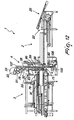
- the actuators 104 are activated and release the rod 90 by retracting the forks 106. Then, with the subsequent activation of the gearmotor 100, by means of the shaft 97 and the belts 94, the rod 90 is raised to a level that lies above the upper face of the mattress M (see Figure 13 ). At the same time, by means of the activation of the gearmotor 93 and the rotation of the rollers 91, rewinding onto the reel 36 is provided for the portion of sheet that otherwise would be loose upon lifting of the rod 90.
- the mattress M is advanced by means of the belts 45 and is positioned below the plate 64, which, by activating the jacks 65, moves downward, compressing the mattress M and reducing its thickness, so that at the end of the packaging operations the volume of the packaged mattress is reduced significantly (however, it is noted that in Figure 13 the mattress is not shown in the compressed position).
- the lateral heat-sealing units 72, 73 are activated and, by heat-scaling the superimposed lateral flaps of the sheet, complete the perimetric closure of the sheet, providing a hermetically closed wrapping.
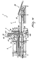
- the plate 64 is lifted again, thus releasing the mattress M so that by activating the belts 45 in the opposite direction B, the mattress, passing below the rod 90, can be transferred onto the conveyor 2 (see Figure 14 ).
- the rod 90 is lowered again below the plane of the rollers 13, 14, so as to stretch a new portion of sheet through the opening 75, thus restoring the initial conditions that make it possible to form a second wrapping in the manner described above for forming the first wrapping.
- the invention achieves perfectly the intended aim and objects.
- the apparatus it is possible to obtain two separate wrappings, so that the outer one can be removed easily in case of damage or for various reasons, for example for reasons of presentability of the contained product, or in case of undergone damage and so forth.
- a gear 108 is provided, which is keyed to one end of the fixing rod 90 and is arranged adjacent to the plane of advancement of the fork 106, so as not to interfere with said fork.
- a pinion 109 is supported at the lower end of the channel 89 and is adapted to mesh with the gear 108 when said gear is positioned at the lower stroke limit.
- the pinion 109 is actuated by means of a gearmotor 110, which is mounted on a post 111 jointly connected to the base 99.
- the function of the gearmotor 110 is to impart to the gear 108, once it has been meshed with the pinion 109 and at the end of the closure of each wrapping, a rotation by means of which a number of turns is transmitted to the rod 90 which is sufficient to rewind a portion of the sheet that might remain loose after heat-sealing and cutting and restore the spreading thereof that is necessary to ensure the wrapping of the sheet around the mattress.
- the portion wrapped around the rod 90 can be unwound on the belts 45 at the same advancement speed as the mattress, so as to avoid the sliding of the mattress on the underlying sheet portion and ensure perfect spreading of the sheet below the mattress.
- Figures 15 , 16 illustrate a further embodiment, which makes it possible to provide packaging by using two sheets taken from two different reels and is therefore capable of forming two wrappings that have different aesthetic characteristics, or of providing an outer wrapping with stronger sheets or to function as a support for advertising messages and so forth.
- the variation provides, to the side of the first reel 36, a second reel 112, which is also supported by a pair of rollers 113 actuated by a gearmotor 114 mounted on the shoulder 102.
- the second sheet 115 is wrapped around the reel 112, its end being fixed to a second fixing rod 116, whose opposite ends are guided in the same channels 89 in which the rod 90 is guided.
- Two actuators 117, 118 are associated with each shoulder 102, below the rollers 91, for the actuation of respective arms 119, 120 which are substantially horizontal.
- the arms 119, 120 move between a position of engagement in the channels 89 and a position of extraction from them through adapted recesses formed in the shoulders of the channels.
- the actuators 117, 118 are actuated alternately for switching the drawing of the sheets from one reel to the other after formation of the first wrapping.
- the rod 90 for fixing the sheet 38 is lifted by the forks 106 to the height of the lower arm 120 and then retracted out of the channels 89 by the actuators 118.
- the arms 119, 120 are curved upward, so that the rod 90 can continue to be retained on the arms 120, allowing the forks 106 to be retracted and lifted to the height of the arms 119 on which the rod 116 was deposited earlier during formation of the first wrapping.
- the forks 106 are activated to engage the upper rod 116 and the arms 119 are disengaged from the channels 89 by activation of the actuators 117, so that by actuation of the belts 94 the rod 116 is lowered below the plane of the rollers 13, 14 for being able to proceed with the formation of the second wrapping and the completion of the packaging process.
- both rods 90 and 116 are each provided, at at least one end, with a gear 108, 121, and at least the fork 106, which is adjacent to the gears 108, 121 and therefore cooperates with the arms 119, 120, has a toothed sector 122, which is guided in a U-shaped member 123 that is fixed to one face of the fork 106.
- the toothed sector 122 is connected to the stem of an actuator 124 that is fixed to the opposite face of the fork.
- the toothed sector 122 by engaging the set of teeth of the gears 108, 121, can block the rotation of the rods 90, 116 during movements along the channels 89 or during the steps for wrapping and unwinding the sheets on the part of the elements 109, 111.
- additional toothed sectors 125, 126 are jointly connected to the arms 119, 120 and, by actuation of the actuators 117, 118, engage the gears 108, 121, retaining the rods 90, 116 at the heights provided for pickup by the forks 106.
Landscapes
- Engineering & Computer Science (AREA)
- Mechanical Engineering (AREA)
- Basic Packing Technique (AREA)
- Buffer Packaging (AREA)
- Packaging Of Special Articles (AREA)
- Auxiliary Devices For And Details Of Packaging Control (AREA)
Claims (16)
- Verfahren zum Verpacken einer Matratze in eine Verpackung, umfassend:- Bereitstellen einer ersten Fördereinrichtung (2) für den Vorschub der Matratze (M) und einer zweiten Fördereinrichtung (3) zum Aufnehmen und Überführen der Matratze, so dass eine Matratzenauflagefläche (45, 13-14) gebildet ist und eine Abstandsöffnung (75) zwischen den Fördereinrichtungen derart gebildet ist, dass sie von einer Matratze überbrückt werden kann, die durch geeignete Verschiebemittel (22, 13-14, 45) von einer Fördereinrichtung zur anderen bewegt wird,- Bereitstellen einer Aufrollung (39) über den Fördereinrichtungen mit einer Folie (38), die heißversiegelt werden kann, und deren eines Ende mit einem Befestigungselement (90) verbunden wird, das durch die Öffnung geführt wird,- Bereitstellen von Mitteln (94-106) zum Einrücken und Betätigen des Elements zum Befestigen der Folie (38) zwischen einer Position, die unter der Auflagefläche (45, 13-14) liegt, in der die Folie durch die Öffnung (75) gezogen wird, und einer Position, die über der Auflagefläche auf einer solchen Höhe liegt, dass der Durchtritt einer Matratze (M) zwischen der Auflagefläche und dem Befestigungselement (90) ermöglicht ist,- Bereitstellen von Heißversiegelungs- und Schneidmitteln (72-73, 76-77) über der Auflagefläche, die synchron zum Befestigungselement und den Matratzenverschiebemitteln betrieben werden können, zum- in einem ersten Verfahrensschritt, Halten des Befestigungselements (90) unter der Auflagefläche und Auslösen des Vorschubs der Matratze von der ersten Fördereinrichtung (2) zur zweiten Fördereinrichtung (3), um das Wickeln der Folie in einer Schlinge um die Matratze und das allseitige Schließen durch Heißversiegeln und Schneiden der Folie und Bilden einer ersten Umhüllung, die von der von der Aufrollung abgerollten Folie getrennt ist, zu bewirken,- in einem zweiten Schritt, Anheben des Befestigungselements (90) für die Folie über die Auflagefläche (45, 13-14) und Überführen der Matratze auf die Vorschubfördereinrichtung (2),- in einem dritten Schritt, Rückführen des Befestigungselements unter die Auflagefläche (45, 13-14) und- in einem vierten Schritt, Bewirken des Vorschubs der Matratze auf der zweiten Aufnahme- und Überführungsfördereinrichtung (3), um eine zweite Folie um die erste Umhüllung, zu wickeln und das folgende Heißversiegeln und Schneiden der Folie durchzuführen, wobei eine zweite Umhüllung gebildet wird, die von der ersten separat ist.
- Vorrichtung zum Verpacken einer Matratze in eine Verpackung, dadurch gekennzeichnet, dass sie umfasst:eine erste Fördereinrichtung (2) für den Vorschub der Matratze (M) und eine zweite Fördereinrichtung (3) zum Aufnehmen und Überführen der Matratze, wobei die Fördereinrichtungen eine Auflagefläche (45, 13-14) bilden und durch eine Öffnung (75) voneinander beabstandet sind, Mittel (34-37, 43-49) zum Betätigen der Fördereinrichtungen, um die Matratze durch Überbrücken der Öffnung von einer Fördereinrichtung zur anderen zu überführen, eine Struktur (55) zum Lagern einer Aufrollung (39) mit einer Folie (38), die heißversiegelt werden kann, über den Fördereinrichtungen, Mittel (94-101) zum Einrücken eines Elements (90) zum Befestigen des Endes der Folie, die von der Aufrollung abgerollt ist, Mittel (89) zum Führen des Befestigungselements durch die Öffnung zwischen einer unteren Position, die unter der Auflagefläche liegt und in der die Folie durch die Öffnung gezogen wird, und einer oberen Position, die über der Auflagefläche auf einer solchen Höhe liegt, dass der Durchtritt einer Matratze zwischen der Auflagefläche (45, 13-14) und dem Befestigungselement (90) ermöglicht ist, Heißversiegelungsmittel (76, 72-73), die über der Auflagefläche angeordnet sind, wobei die Mittel zum Betätigen des Befestigungselements, zum Heißversiegeln und Schneiden und Verschieben der Matratze funktional so koordiniert sind, dass in einem ersten Schritt, wenn das Befestigungselement (90) unter der Auflagefläche angeordnet ist, die Matratze von der ersten Vorschubfördereinrichtung (2) zur zweiten Aufnahme- und Überführungsfördereinrichtung (3) überführt wird, wodurch Umhüllen und Verschließen in einer Schlinge durch Heißversiegeln und Schneiden der Folie um die Matratze und die Bildung einer ersten Umhüllung bewirkt werden, in einem zweiten Schritt das Befestigungselement über die Auflagefläche angehoben und die Matratze auf die Vorschubfördereinrichtung (2) zurückgeführt wird, in einem dritten Schritt das Befestigungselement (90) erneut unter die Auflagefläche abgesenkt wird, so dass die Folie erneut durch die Öffnung (75) gezogen wird, in einem vierten Schritt die Matratze erneut auf die Aufnahme- und Überführungsfördereinrichtung (3) überführt wird und das Wickeln einer zweiten Folie um die erste Umhüllung, das Heißversiegeln und Schneiden der Folie unter Bildung einer zweiten Umhüllung, die nicht mit der ersten verbunden ist, abgeschlossen werden.
- Vorrichtung nach Anspruch 2, dadurch gekennzeichnet, dass die erste Vorschubfördereinrichtung (2) zwei Reihen von Rollen (13, 14), die zugehörige Rollgänge bilden, zwischen denen eine Öffnung (15) bleibt, und einen Schieber (22) umfasst, der sich entlang der Öffnung bewegen kann und dazu ausgebildet ist, dass er an der zu verpackenden Matratze (M) wirkt, die auf die Rollen gelegt ist, um die Matratze auf die zweite Fördereinrichtung (3) zu überführen.
- Vorrichtung nach Anspruch 3, dadurch gekennzeichnet, dass die Rollen (13, 14) sich während des Vorschubs des Schiebers (22) in eine Richtung (A) frei drehen können, um die Matratze zur zweiten Fördereinrichtung (3) zu überführen, und zwangsweise in die entgegengesetzte Richtung (B) betätigt werden können, wenn die Matratze von der zweiten Fördereinrichtung auf die Rollgänge (13, 14) zurückläuft.
- Vorrichtung nach einem der Ansprüche 3 und 4, dadurch gekennzeichnet, dass der Schieber (22) aus einer Stange (23) besteht, die sich über den Rollgängen (13, 14) bewegen kann und mit einem Gleitstück (17) verbunden ist, das auf Führungen (102) verschiebbar ist, die unter dem Rollgang angeordnet sind, und in einer umkehrbaren Bewegung betätigt werden kann.
- Vorrichtung nach einem der Ansprüche 3 bis 4, dadurch gekennzeichnet, dass die Rollen (13, 14) jeder Reihe von einem Getriebemotor (36, 37) betätigt werden, der die Rollen mittels einer Transmission betätigt, die eine Welle (34, 35) umfasst, die im rechten Winkel zu den Rollen gelagert ist und mit diesen durch zugehörige Riemen (38) verbunden ist.
- Vorrichtung nach einem der Ansprüche 3 bis 6, dadurch gekennzeichnet, dass der Vorschubfördereinrichtung (2) eine Aufgabeeinrichtung (25) für Matratzen zugeordnet und in der Art mit Riemen (25) ausgebildet ist, deren Ende zum Abladen der Matratzen über den Rollgängen Liegt.
- Vorrichtung nach Anspruch 2, dadurch gekennzeichnet, dass die Aufnahme- und Überführungsfördereinrichtung (3) eine Mehrzahl von horizontalen Riemen (45) in Gleitkontakt auf einer Trägerfläche (48) umfasst, die eine Ebene bilden, die im Wesentlichen koplanar zur Ebene der Rollen (13, 14) liegt, wobei die Riemen durch einen reversiblen Getriebemotor (49) betätigt werden.
- Vorrichtung nach Anspruch 8, dadurch gekennzeichnet, dass sie eine Platte (64) umfasst, die von der oben genannten Fläche (48) getragen ist und mit dieser eine Kammer zum Aufnehmen der zu verpackenden Matratze bildet, wobei Mittel (60-65) zur Bewegung der Platte von einer angehobenen Position in eine abgesenkte Position zum Komprimieren der Matratze vorgesehen sind.
- Vorrichtung nach Anspruch 9, dadurch gekennzeichnet, dass die Heißversiegelungsmittel (72, 73) seitlich zur Platte (64) angeordnet sind, um die Seitenkanten der Verpackungsfolie, die um die in diesem Abteil angeordnete Matratze gewickelt ist, heiß zu versiegeln.
- Vorrichtung nach Anspruch 10, dadurch gekennzeichnet, dass die Heißversiegelungsstäbe (72, 73) auf Schlitten (67) getragen sind, die an den Seiten der Ebene mit Riemen (45) und in einem einstellbaren Abstand dazu angeordnet sind.
- Vorrichtung nach einem der Ansprüche 2 bis 11, dadurch gekennzeichnet, dass die Struktur (55) umfasst: zwei Säulen (51), an denen oben Rollen gelagert sind, die mindestens eine Aufrollung (39) für eine Folie zum Ausbilden der Verpackung tragen, ein erstes Paar Führungen (89), die vertikal den Säulen (51) zugeordnet sind, um die entgegengesetzten Enden einer Stange (90) zu führen, die das Element zum Befestigen der Folie (38) darstellt, ein zweites Paar Führungen (102), die zu den ersten (89) parallel sind, um zugehörige Gleitblöcke (103) zum Lagern von Aktuatoren (104) zu führen, die Elemente (106) zum Ergreifen der Enden der Stange (90) betätigen, wobei die Gleitblöcke durch die Mittel (94-101) so betätigt werden können, dass die Stange zwischen einer Position, die unter dem Rollengang liegt, und einer Position, die über dem Rollengang liegt, auf eine Höhe, die größer ist als die Dicke der Matratze, angehoben und abgesenkt werden kann.
- Vorrichtung nach Anspruch 12, dadurch gekennzeichnet, dass eine zweite Aufrollung (112) für eine Folie (115) auf der Struktur (55) angeordnet ist, wobei die Folie (115) ein Ende aufweist, das an einer zweiten Stange (116) befestigt ist, deren entgegengesetzte Enden gleitend in der gleichen Führung (89) der ersten Stange (90) geführt sind, wobei Stoppmittel (119, 120) vorgesehen sind, um die Stangen in Bezug auf die Auflagefläche auf einer Höhe zu halten, die größer ist als die Dicke der Matratze, und durch Steuermittel gesteuert sind, um die einzelne Freigabe der Eingriffelement (106) zu ermöglichen.
- Vorrichtung nach einem der Ansprüche 12 und 13, dadurch gekennzeichnet, dass die Stoppmittel Arme (119, 120) umfassen, die von Aktuatoren (117, 118), die gemeinsam mit der Struktur (55) verbunden sind, zwischen einer Halteposition und einer Freigabeposition der Stangen (90, 116) betätigt werden.
- Vorrichtung nach einem der Ansprüche 12-14, dadurch gekennzeichnet, dass an den entgegengesetzten Enden jeder Stange (90, 116) ein Zahnrad (108, 121) angebracht ist, und dass das Eingriffelement aus einer Gabel (106) gebildet ist, auf der ein gezahnter Abschnitt (122) verschiebbar zugeordnet ist, der von einem Aktuator (124) zwischen einer Position zum Eingriff am Zahnrad (108, 121), um die Drehung der Stange (90, 116) zu blockieren, und einer Position zum Lösen aus dem Zahnrad (108, 121), um die Drehung der Stange (90, 116) zu ermöglichen, betätigt wird.
- Vorrichtung nach einem der Ansprüche 12-15, dadurch gekennzeichnet, dass am unteren Ende der ersten Führungen (89) ein Ritzel (109) vorgesehen ist, das von einem Getriebemotor (110) betätigt werden kann und dazu ausgebildet ist, dass es mit dem Zahnrad (108, 121) zusammenwirkt, das auf der Stange angebracht ist, um die Folie zu ziehen.
Applications Claiming Priority (1)
| Application Number | Priority Date | Filing Date | Title |
|---|---|---|---|
| ITBO2008A000614A IT1391358B1 (it) | 2008-10-08 | 2008-10-08 | Procedimento ed apparecchiatura per confezionare un materasso in un imballaggio composto da piu involucri disposti uno nell'altro |
Publications (2)
| Publication Number | Publication Date |
|---|---|
| EP2174871A1 EP2174871A1 (de) | 2010-04-14 |
| EP2174871B1 true EP2174871B1 (de) | 2011-08-03 |
Family
ID=41261662
Family Applications (1)
| Application Number | Title | Priority Date | Filing Date |
|---|---|---|---|
| EP09172295A Not-in-force EP2174871B1 (de) | 2008-10-08 | 2009-10-06 | Verfahren und Vorrichtung zum Verpacken von Matratzen in einer Verpackung aus mehreren Wicklungen, die ineinander angeordnet sind |
Country Status (5)
| Country | Link |
|---|---|
| US (1) | US20100083620A1 (de) |
| EP (1) | EP2174871B1 (de) |
| AT (1) | ATE518759T1 (de) |
| ES (1) | ES2367096T3 (de) |
| IT (1) | IT1391358B1 (de) |
Families Citing this family (14)
| Publication number | Priority date | Publication date | Assignee | Title |
|---|---|---|---|---|
| JP5928139B2 (ja) * | 2012-05-08 | 2016-06-01 | ブラザー工業株式会社 | 包装装置 |
| US9481481B2 (en) | 2012-11-15 | 2016-11-01 | Brother Kogyo Kabushiki Kaisha | Packaging device |
| JP5962450B2 (ja) | 2012-11-15 | 2016-08-03 | ブラザー工業株式会社 | 包装装置 |
| CN105366092B (zh) * | 2015-12-01 | 2018-07-27 | 韩岳平 | 自动封包设备 |
| JP6709050B2 (ja) * | 2015-12-28 | 2020-06-10 | 株式会社イシダ | 包装装置 |
| CN106428724B (zh) * | 2016-10-18 | 2018-12-04 | 浙江鼎业机械设备有限公司 | 一种薄膜封切机 |
| CN107054723B (zh) * | 2017-04-12 | 2019-01-01 | 杨文俊 | 一种石膏线条覆膜装置 |
| CN108569542B (zh) * | 2018-05-18 | 2024-06-07 | 佛山市源田床具机械有限公司 | 床垫翻转装置 |
| CN109625454B (zh) * | 2018-12-13 | 2020-11-27 | 杭州永创智能设备股份有限公司 | 一种旋转驱动式封切装置 |
| CN109775054A (zh) * | 2019-03-08 | 2019-05-21 | 鄂州宝丰金属棉技术股份有限公司 | 一种一体式包装盒塑料膜封口装置 |
| CN113460415A (zh) * | 2021-06-28 | 2021-10-01 | 广东耐锢科技有限公司 | 一种床垫自动包装机 |
| CN115195205B (zh) * | 2022-08-08 | 2023-11-21 | 漯河市双发塑料印刷有限公司 | 一种食品包装袋热封切割装置 |
| CN117657538B (zh) * | 2022-09-01 | 2025-12-05 | 江苏众恒可来比家具有限公司 | 一种床垫制作用加工打包一体化设备 |
| CN118770673A (zh) * | 2024-09-10 | 2024-10-15 | 杭州瑞丰汉艺纺织品有限公司 | 一种纺织布包装装置 |
Family Cites Families (15)
| Publication number | Priority date | Publication date | Assignee | Title |
|---|---|---|---|---|
| US2700459A (en) * | 1949-05-27 | 1955-01-25 | Anspacher Edgar | Mattress package and method of wrapping |
| US2937485A (en) * | 1953-10-05 | 1960-05-24 | Howard M Wall | Packaging machine for flat articles |
| US3016671A (en) * | 1959-09-25 | 1962-01-16 | William F Stremke | Wrapping machine with return conveyor |
| US3153308A (en) * | 1961-07-31 | 1964-10-20 | Stanley G Yount | Machine and method for wrapping large objects |
| US4479572A (en) * | 1981-11-10 | 1984-10-30 | Merz William J | Conveyor system |
| EP0120251B1 (de) * | 1983-03-22 | 1987-07-08 | Ferag AG | Verfahren und Vorrichtung zum Umwickeln von vorzugsweise quaderförmigen Gegenständen mit einem bahnförmigen Umwickelmaterial |
| JPH0818656B2 (ja) * | 1986-10-15 | 1996-02-28 | ソニー株式会社 | ロ−ラコンベヤ |
| DE19806133A1 (de) * | 1998-02-14 | 1999-08-19 | Topack Verpacktech Gmbh | Rollenförderer zum Fördern von Stapeln |
| EP1123246A4 (de) * | 1998-07-31 | 2003-04-09 | Shuttleworth Inc | Förderband mit niedriger elektronischer arbeitsfähigkeit |
| IT1311101B1 (it) * | 1999-10-19 | 2002-02-28 | Resta Srl | Dispositivo per il ricambio automatico della bobina di alimentazionedel foglio con cui vengono avvolti i materassi e simili in macchine |
| IT1320919B1 (it) * | 2000-03-14 | 2003-12-10 | Resta Srl | Macchina confezionatrice di materassi in un foglio svolto in continuoda una bobina. |
| ITBO20000733A1 (it) * | 2000-12-20 | 2002-06-20 | Gianluigi Gamberini | Macchina per il confezionamento di pile di articoli multi - falda di carta o simili entro relativi involucri ottenuti da fogli di avvolgimen |
| DE10162483A1 (de) * | 2001-12-19 | 2003-11-06 | Blicker Silvia | Vorrichtung zur Transportsicherung eines- oder mehrlagigen Stapels aus einzelnen Behältern |
| US20060167445A1 (en) * | 2002-08-27 | 2006-07-27 | Gal Shafirstein | Selective conductive interstitial thermal therapy device |
| EP1566337A1 (de) * | 2004-02-20 | 2005-08-24 | Rockwool International A/S | Vorrichtung und Verpackungsverfahren für die Verpackung von Mineralwollprodukte, und Mineralwollverpackung |
-
2008
- 2008-10-08 IT ITBO2008A000614A patent/IT1391358B1/it active
-
2009
- 2009-10-02 US US12/588,058 patent/US20100083620A1/en not_active Abandoned
- 2009-10-06 AT AT09172295T patent/ATE518759T1/de not_active IP Right Cessation
- 2009-10-06 ES ES09172295T patent/ES2367096T3/es active Active
- 2009-10-06 EP EP09172295A patent/EP2174871B1/de not_active Not-in-force
Also Published As
| Publication number | Publication date |
|---|---|
| US20100083620A1 (en) | 2010-04-08 |
| IT1391358B1 (it) | 2011-12-13 |
| ATE518759T1 (de) | 2011-08-15 |
| ES2367096T3 (es) | 2011-10-28 |
| ITBO20080614A1 (it) | 2010-04-09 |
| EP2174871A1 (de) | 2010-04-14 |
Similar Documents
| Publication | Publication Date | Title |
|---|---|---|
| EP2174871A1 (de) | Verfahren und Vorrichtung zum Verpacken von Matratzen in einer Verpackung aus mehreren Wicklungen, die ineinander angeordnet sind | |
| EP2379412B1 (de) | Verpackung für matratzen und vorrichtung zur bereitstellung der verpackung | |
| US20120027555A1 (en) | Palletizer with box layer preparation | |
| NL1029106C2 (nl) | Machine voor het palletiseren van voorwerpen, zoals verpakkingsdozen. | |
| ITRE20090004A1 (it) | '' dispositivo di palettizzazi0ne '' | |
| US6735923B1 (en) | Mattress packaging machine including an automatic roll replacement device | |
| EP1136359B1 (de) | Maschine zum verpacken von matratzen in einer von einer bobine kontinuierlich abgezogenen folie | |
| CN210526937U (zh) | 一种香肠封装机 | |
| US4108061A (en) | Palletizer with tier sheet inserter and banding means | |
| RS62153B1 (sr) | Mašina za umotavanje | |
| NL1029107C2 (nl) | Machine voor het palletiseren van voorwerpen, zoals verpakkingsdozen. | |
| EP2452882A1 (de) | Vorrichtung und Verfahren zur Umhüllung von Produkten | |
| CN113581536A (zh) | 一种条烟拨移装置和采用该拨移装置的条烟包装机 | |
| CN113428398B (zh) | 一种托盘防掉货捆扎设备及捆扎方法 | |
| EP2392513B2 (de) | Anlage und Verfahren zum seitlichen Einwickeln von Produkten mit einer Kunststofffolie | |
| EP1281617B1 (de) | Verfahren und Vorrichtung zum Verpacken eines Produktes, wie eine oder mehrere Scheiben eines Käse- oder Fleischproduktes, in Folienmaterial | |
| CN215707452U (zh) | 一种条烟拨移装置和采用该拨移装置的条烟包装机 | |
| EP2316762B1 (de) | Vorrichtung und Verfahren zum Handhaben von Gegenstandsgruppen in einer Palettieranlage | |
| CN221050087U (zh) | 一种光伏组件生产用托盘更换组件 | |
| CN221050069U (zh) | 柔板打包设备 | |
| CN111516919A (zh) | 一种纸箱自动折盖封箱设备 | |
| EP1580127A1 (de) | Vorrichtung zum Umhüllen von Stückgut mit einer Stetchfolienhaube | |
| EP2572999B1 (de) | Vertikalvorhang-Einschlagvorrichtung mit Multiformat-Zuführer | |
| JP3717947B2 (ja) | 袋封鎖装置 | |
| KR200392129Y1 (ko) | 적층된 샌드위치패널의 선단부결속포장기 |
Legal Events
| Date | Code | Title | Description |
|---|---|---|---|
| PUAI | Public reference made under article 153(3) epc to a published international application that has entered the european phase |
Free format text: ORIGINAL CODE: 0009012 |
|
| AK | Designated contracting states |
Kind code of ref document: A1 Designated state(s): AT BE BG CH CY CZ DE DK EE ES FI FR GB GR HR HU IE IS IT LI LT LU LV MC MK MT NL NO PL PT RO SE SI SK SM TR |
|
| AX | Request for extension of the european patent |
Extension state: AL BA RS |
|
| 17P | Request for examination filed |
Effective date: 20101013 |
|
| GRAP | Despatch of communication of intention to grant a patent |
Free format text: ORIGINAL CODE: EPIDOSNIGR1 |
|
| RIC1 | Information provided on ipc code assigned before grant |
Ipc: B65B 11/58 20060101AFI20101130BHEP |
|
| RIN1 | Information on inventor provided before grant (corrected) |
Inventor name: RESTA, ROBERTO Inventor name: RESTA, PAOLO |
|
| GRAS | Grant fee paid |
Free format text: ORIGINAL CODE: EPIDOSNIGR3 |
|
| GRAA | (expected) grant |
Free format text: ORIGINAL CODE: 0009210 |
|
| AK | Designated contracting states |
Kind code of ref document: B1 Designated state(s): AT BE BG CH CY CZ DE DK EE ES FI FR GB GR HR HU IE IS IT LI LT LU LV MC MK MT NL NO PL PT RO SE SI SK SM TR |
|
| REG | Reference to a national code |
Ref country code: GB Ref legal event code: FG4D |
|
| REG | Reference to a national code |
Ref country code: CH Ref legal event code: EP |
|
| REG | Reference to a national code |
Ref country code: IE Ref legal event code: FG4D |
|
| REG | Reference to a national code |
Ref country code: DE Ref legal event code: R096 Ref document number: 602009001969 Country of ref document: DE Effective date: 20111006 |
|
| REG | Reference to a national code |
Ref country code: ES Ref legal event code: FG2A Ref document number: 2367096 Country of ref document: ES Kind code of ref document: T3 Effective date: 20111028 |
|
| REG | Reference to a national code |
Ref country code: NL Ref legal event code: VDEP Effective date: 20110803 |
|
| LTIE | Lt: invalidation of european patent or patent extension |
Effective date: 20110803 |
|
| PG25 | Lapsed in a contracting state [announced via postgrant information from national office to epo] |
Ref country code: IS Free format text: LAPSE BECAUSE OF FAILURE TO SUBMIT A TRANSLATION OF THE DESCRIPTION OR TO PAY THE FEE WITHIN THE PRESCRIBED TIME-LIMIT Effective date: 20111203 Ref country code: HR Free format text: LAPSE BECAUSE OF FAILURE TO SUBMIT A TRANSLATION OF THE DESCRIPTION OR TO PAY THE FEE WITHIN THE PRESCRIBED TIME-LIMIT Effective date: 20110803 Ref country code: PT Free format text: LAPSE BECAUSE OF FAILURE TO SUBMIT A TRANSLATION OF THE DESCRIPTION OR TO PAY THE FEE WITHIN THE PRESCRIBED TIME-LIMIT Effective date: 20111205 Ref country code: NL Free format text: LAPSE BECAUSE OF FAILURE TO SUBMIT A TRANSLATION OF THE DESCRIPTION OR TO PAY THE FEE WITHIN THE PRESCRIBED TIME-LIMIT Effective date: 20110803 Ref country code: SE Free format text: LAPSE BECAUSE OF FAILURE TO SUBMIT A TRANSLATION OF THE DESCRIPTION OR TO PAY THE FEE WITHIN THE PRESCRIBED TIME-LIMIT Effective date: 20110803 Ref country code: LT Free format text: LAPSE BECAUSE OF FAILURE TO SUBMIT A TRANSLATION OF THE DESCRIPTION OR TO PAY THE FEE WITHIN THE PRESCRIBED TIME-LIMIT Effective date: 20110803 Ref country code: NO Free format text: LAPSE BECAUSE OF FAILURE TO SUBMIT A TRANSLATION OF THE DESCRIPTION OR TO PAY THE FEE WITHIN THE PRESCRIBED TIME-LIMIT Effective date: 20111103 Ref country code: FI Free format text: LAPSE BECAUSE OF FAILURE TO SUBMIT A TRANSLATION OF THE DESCRIPTION OR TO PAY THE FEE WITHIN THE PRESCRIBED TIME-LIMIT Effective date: 20110803 |
|
| REG | Reference to a national code |
Ref country code: AT Ref legal event code: MK05 Ref document number: 518759 Country of ref document: AT Kind code of ref document: T Effective date: 20110803 |
|
| PG25 | Lapsed in a contracting state [announced via postgrant information from national office to epo] |
Ref country code: SI Free format text: LAPSE BECAUSE OF FAILURE TO SUBMIT A TRANSLATION OF THE DESCRIPTION OR TO PAY THE FEE WITHIN THE PRESCRIBED TIME-LIMIT Effective date: 20110803 Ref country code: GR Free format text: LAPSE BECAUSE OF FAILURE TO SUBMIT A TRANSLATION OF THE DESCRIPTION OR TO PAY THE FEE WITHIN THE PRESCRIBED TIME-LIMIT Effective date: 20111104 Ref country code: LV Free format text: LAPSE BECAUSE OF FAILURE TO SUBMIT A TRANSLATION OF THE DESCRIPTION OR TO PAY THE FEE WITHIN THE PRESCRIBED TIME-LIMIT Effective date: 20110803 Ref country code: AT Free format text: LAPSE BECAUSE OF FAILURE TO SUBMIT A TRANSLATION OF THE DESCRIPTION OR TO PAY THE FEE WITHIN THE PRESCRIBED TIME-LIMIT Effective date: 20110803 Ref country code: CY Free format text: LAPSE BECAUSE OF FAILURE TO SUBMIT A TRANSLATION OF THE DESCRIPTION OR TO PAY THE FEE WITHIN THE PRESCRIBED TIME-LIMIT Effective date: 20110803 Ref country code: PL Free format text: LAPSE BECAUSE OF FAILURE TO SUBMIT A TRANSLATION OF THE DESCRIPTION OR TO PAY THE FEE WITHIN THE PRESCRIBED TIME-LIMIT Effective date: 20110803 |
|
| PG25 | Lapsed in a contracting state [announced via postgrant information from national office to epo] |
Ref country code: BE Free format text: LAPSE BECAUSE OF FAILURE TO SUBMIT A TRANSLATION OF THE DESCRIPTION OR TO PAY THE FEE WITHIN THE PRESCRIBED TIME-LIMIT Effective date: 20110803 |
|
| PG25 | Lapsed in a contracting state [announced via postgrant information from national office to epo] |
Ref country code: CZ Free format text: LAPSE BECAUSE OF FAILURE TO SUBMIT A TRANSLATION OF THE DESCRIPTION OR TO PAY THE FEE WITHIN THE PRESCRIBED TIME-LIMIT Effective date: 20110803 Ref country code: SK Free format text: LAPSE BECAUSE OF FAILURE TO SUBMIT A TRANSLATION OF THE DESCRIPTION OR TO PAY THE FEE WITHIN THE PRESCRIBED TIME-LIMIT Effective date: 20110803 |
|
| PG25 | Lapsed in a contracting state [announced via postgrant information from national office to epo] |
Ref country code: RO Free format text: LAPSE BECAUSE OF FAILURE TO SUBMIT A TRANSLATION OF THE DESCRIPTION OR TO PAY THE FEE WITHIN THE PRESCRIBED TIME-LIMIT Effective date: 20110803 Ref country code: EE Free format text: LAPSE BECAUSE OF FAILURE TO SUBMIT A TRANSLATION OF THE DESCRIPTION OR TO PAY THE FEE WITHIN THE PRESCRIBED TIME-LIMIT Effective date: 20110803 Ref country code: MC Free format text: LAPSE BECAUSE OF NON-PAYMENT OF DUE FEES Effective date: 20111031 |
|
| PLBE | No opposition filed within time limit |
Free format text: ORIGINAL CODE: 0009261 |
|
| STAA | Information on the status of an ep patent application or granted ep patent |
Free format text: STATUS: NO OPPOSITION FILED WITHIN TIME LIMIT |
|
| PG25 | Lapsed in a contracting state [announced via postgrant information from national office to epo] |
Ref country code: DK Free format text: LAPSE BECAUSE OF FAILURE TO SUBMIT A TRANSLATION OF THE DESCRIPTION OR TO PAY THE FEE WITHIN THE PRESCRIBED TIME-LIMIT Effective date: 20110803 |
|
| 26N | No opposition filed |
Effective date: 20120504 |
|
| REG | Reference to a national code |
Ref country code: IE Ref legal event code: MM4A |
|
| REG | Reference to a national code |
Ref country code: DE Ref legal event code: R097 Ref document number: 602009001969 Country of ref document: DE Effective date: 20120504 |
|
| PG25 | Lapsed in a contracting state [announced via postgrant information from national office to epo] |
Ref country code: IE Free format text: LAPSE BECAUSE OF NON-PAYMENT OF DUE FEES Effective date: 20111006 |
|
| PG25 | Lapsed in a contracting state [announced via postgrant information from national office to epo] |
Ref country code: MK Free format text: LAPSE BECAUSE OF FAILURE TO SUBMIT A TRANSLATION OF THE DESCRIPTION OR TO PAY THE FEE WITHIN THE PRESCRIBED TIME-LIMIT Effective date: 20110803 Ref country code: MT Free format text: LAPSE BECAUSE OF FAILURE TO SUBMIT A TRANSLATION OF THE DESCRIPTION OR TO PAY THE FEE WITHIN THE PRESCRIBED TIME-LIMIT Effective date: 20110803 |
|
| PG25 | Lapsed in a contracting state [announced via postgrant information from national office to epo] |
Ref country code: SM Free format text: LAPSE BECAUSE OF FAILURE TO SUBMIT A TRANSLATION OF THE DESCRIPTION OR TO PAY THE FEE WITHIN THE PRESCRIBED TIME-LIMIT Effective date: 20110803 |
|
| PG25 | Lapsed in a contracting state [announced via postgrant information from national office to epo] |
Ref country code: LU Free format text: LAPSE BECAUSE OF NON-PAYMENT OF DUE FEES Effective date: 20111006 |
|
| PG25 | Lapsed in a contracting state [announced via postgrant information from national office to epo] |
Ref country code: BG Free format text: LAPSE BECAUSE OF FAILURE TO SUBMIT A TRANSLATION OF THE DESCRIPTION OR TO PAY THE FEE WITHIN THE PRESCRIBED TIME-LIMIT Effective date: 20111103 |
|
| PG25 | Lapsed in a contracting state [announced via postgrant information from national office to epo] |
Ref country code: TR Free format text: LAPSE BECAUSE OF FAILURE TO SUBMIT A TRANSLATION OF THE DESCRIPTION OR TO PAY THE FEE WITHIN THE PRESCRIBED TIME-LIMIT Effective date: 20110803 |
|
| PG25 | Lapsed in a contracting state [announced via postgrant information from national office to epo] |
Ref country code: HU Free format text: LAPSE BECAUSE OF FAILURE TO SUBMIT A TRANSLATION OF THE DESCRIPTION OR TO PAY THE FEE WITHIN THE PRESCRIBED TIME-LIMIT Effective date: 20110803 |
|
| REG | Reference to a national code |
Ref country code: CH Ref legal event code: PL |
|
| GBPC | Gb: european patent ceased through non-payment of renewal fee |
Effective date: 20131006 |
|
| PG25 | Lapsed in a contracting state [announced via postgrant information from national office to epo] |
Ref country code: CH Free format text: LAPSE BECAUSE OF NON-PAYMENT OF DUE FEES Effective date: 20131031 Ref country code: LI Free format text: LAPSE BECAUSE OF NON-PAYMENT OF DUE FEES Effective date: 20131031 Ref country code: GB Free format text: LAPSE BECAUSE OF NON-PAYMENT OF DUE FEES Effective date: 20131006 |
|
| REG | Reference to a national code |
Ref country code: FR Ref legal event code: PLFP Year of fee payment: 7 |
|
| REG | Reference to a national code |
Ref country code: FR Ref legal event code: PLFP Year of fee payment: 8 |
|
| PGFP | Annual fee paid to national office [announced via postgrant information from national office to epo] |
Ref country code: DE Payment date: 20161026 Year of fee payment: 8 |
|
| REG | Reference to a national code |
Ref country code: FR Ref legal event code: PLFP Year of fee payment: 9 |
|
| REG | Reference to a national code |
Ref country code: DE Ref legal event code: R119 Ref document number: 602009001969 Country of ref document: DE |
|
| PG25 | Lapsed in a contracting state [announced via postgrant information from national office to epo] |
Ref country code: DE Free format text: LAPSE BECAUSE OF NON-PAYMENT OF DUE FEES Effective date: 20180501 |
|
| PGFP | Annual fee paid to national office [announced via postgrant information from national office to epo] |
Ref country code: ES Payment date: 20181123 Year of fee payment: 10 Ref country code: IT Payment date: 20181019 Year of fee payment: 10 Ref country code: FR Payment date: 20181220 Year of fee payment: 10 |
|
| PG25 | Lapsed in a contracting state [announced via postgrant information from national office to epo] |
Ref country code: FR Free format text: LAPSE BECAUSE OF NON-PAYMENT OF DUE FEES Effective date: 20191031 Ref country code: IT Free format text: LAPSE BECAUSE OF NON-PAYMENT OF DUE FEES Effective date: 20191006 |
|
| REG | Reference to a national code |
Ref country code: ES Ref legal event code: FD2A Effective date: 20210301 |
|
| PG25 | Lapsed in a contracting state [announced via postgrant information from national office to epo] |
Ref country code: ES Free format text: LAPSE BECAUSE OF NON-PAYMENT OF DUE FEES Effective date: 20191007 |
|
| P01 | Opt-out of the competence of the unified patent court (upc) registered |
Effective date: 20230529 |