EP2174895B1 - Dispositif et procédé économique de formation de couches de conteneurs - Google Patents
Dispositif et procédé économique de formation de couches de conteneurs Download PDFInfo
- Publication number
- EP2174895B1 EP2174895B1 EP09158416A EP09158416A EP2174895B1 EP 2174895 B1 EP2174895 B1 EP 2174895B1 EP 09158416 A EP09158416 A EP 09158416A EP 09158416 A EP09158416 A EP 09158416A EP 2174895 B1 EP2174895 B1 EP 2174895B1
- Authority
- EP
- European Patent Office
- Prior art keywords
- packing unit
- gripper
- packing
- conveyor
- layers
- Prior art date
- Legal status (The legal status is an assumption and is not a legal conclusion. Google has not performed a legal analysis and makes no representation as to the accuracy of the status listed.)
- Active
Links
Images


Classifications
-
- B—PERFORMING OPERATIONS; TRANSPORTING
- B65—CONVEYING; PACKING; STORING; HANDLING THIN OR FILAMENTARY MATERIAL
- B65G—TRANSPORT OR STORAGE DEVICES, e.g. CONVEYORS FOR LOADING OR TIPPING, SHOP CONVEYOR SYSTEMS OR PNEUMATIC TUBE CONVEYORS
- B65G47/00—Article or material-handling devices associated with conveyors; Methods employing such devices
- B65G47/02—Devices for feeding articles or materials to conveyors
- B65G47/04—Devices for feeding articles or materials to conveyors for feeding articles
- B65G47/06—Devices for feeding articles or materials to conveyors for feeding articles from a single group of articles arranged in orderly pattern, e.g. workpieces in magazines
- B65G47/08—Devices for feeding articles or materials to conveyors for feeding articles from a single group of articles arranged in orderly pattern, e.g. workpieces in magazines spacing or grouping the articles during feeding
- B65G47/084—Devices for feeding articles or materials to conveyors for feeding articles from a single group of articles arranged in orderly pattern, e.g. workpieces in magazines spacing or grouping the articles during feeding grouping articles in a predetermined 2-dimensional pattern
- B65G47/086—Devices for feeding articles or materials to conveyors for feeding articles from a single group of articles arranged in orderly pattern, e.g. workpieces in magazines spacing or grouping the articles during feeding grouping articles in a predetermined 2-dimensional pattern cubiform articles
-
- B—PERFORMING OPERATIONS; TRANSPORTING
- B65—CONVEYING; PACKING; STORING; HANDLING THIN OR FILAMENTARY MATERIAL
- B65G—TRANSPORT OR STORAGE DEVICES, e.g. CONVEYORS FOR LOADING OR TIPPING, SHOP CONVEYOR SYSTEMS OR PNEUMATIC TUBE CONVEYORS
- B65G57/00—Stacking of articles
- B65G57/32—Stacking of articles characterised by stacking during transit
Definitions
- the present invention relates to an apparatus for economically forming bundle layers.
- the device comprises at least one feed conveyor for feeding the containers. Further, at least one further conveyor is provided downstream of the Zuleit teller. The further conveyor is associated with at least one gripper for positioning and / or rotating the container. At least one outlet conveyor is connected downstream of the further conveyor, on which the positioned and / or rotated containers can be brought together with means for form-fitting package layers.
- the invention relates to a method for the economic molding of bundle layers.
- the U.S. Patent 3,587,876 discloses a generic device for loading pallets. With this device, individual containers of the device can be fed and rotated by 90 °. The containers are assigned for this purpose in fixed paths to the claw-like rotary elements, which then rotate the containers. With the rotary elements, it is only possible to turn a container. The rotated bundles are later assembled by side-mounted elements to form a layer and then stacked layer by layer on a pallet.
- EP 1 046 598 A1 a device for producing palettiertransporter layers of container packs is disclosed.
- the supplied containers are on a conveyor belt by a plurality of grippers rotated by 90 ° and / or offset. These grippers are attached to linear units, which are arranged diagonally above the conveyor belt and parallel to each other. Each gripper is tied to a fixed work area by its installation on one of the linear units. After turning and / or positioning the containers, these are combined to form bundle layers.
- EP 0 761 578 B1 discloses a method and an apparatus for assembling bundle layers and their palletizing.
- the sales units are delivered with two bands.
- the sales units are then picked up by robots and put together to layers on a third conveyor belt.
- the layers are recorded and deposited layer by layer on a pallet.
- the US Patent Application 2005/0246056 A1 discloses a device for positioning of containers and their palletizing.
- the containers are delivered with a conveyor. With a second conveyor, the containers are separated for the subsequent work steps. With a gripper, the containers are rotated and positioned according to a predetermined scheme for palletizing on the conveyor. In the further course, the containers are stopped by a stop until the amount of containers that is required for a package layer is present. Subsequently, the package layers are transferred via a fixed plane to the pallet with a pusher unit arranged above the conveyor. Other packaged layers can be applied by lowering the pallet.
- the containers are delivered on two parallel conveyors. The containers are then assembled into groups, which are then completely turned and positioned by the gripper. So it is possible to handle several containers at the same time in one operation and to provide for the formation of a container layer.
- the European patent EP 1 456 101 B1 discloses a method and apparatus for stacking packaged goods.
- the packaged goods are fed in series (shock to burst) of the device.
- By means of two separating conveyor sections the packaged goods are separated.
- In the course of the packaged goods are rotated by means of the rotary conveyor sections.
- the packaged goods are transported via two row conveyor sections until they enter the delivery conveyor.
- the packaged goods pushed together and pushed with a slide transversely to the previous conveying direction in the station for layering. From the station for layer formation, the layers of packaged goods are fed to the palletizing station with the layer conveyor.
- the invention has for its object to provide a device for the economic molding of bundle layers.
- a further object of the invention is to provide a method by which the economic molding of bundle layers is possible.
- the device according to the invention for the economic molding of bundle layers consists of at least one feed conveyor with which the bundles of the device are supplied for economical forming of bundle layers. From the feed conveyor, the containers are fed to at least one other conveyor. The at least one further conveyor is associated with at least one gripper for positioning and / or rotating the container.
- the at least one gripper is configured such that at least one container can be positioned and / or rotated with it. On the positioned and / or rotated container, at least one further container, in the same orientation, is deposited with the gripper. This means that the second container is placed on the first positioned and / or rotated container in the same orientation on the first container. As a result, the first and the second container form a stack of the same orientation after the second container has been deposited.
- the gripper is designed such that it can position and / or rotate at least two containers. For this purpose, two containers are stacked on top of each other with the gripper. The resulting stack of containers is positioned and / or rotated with the gripper in one operation.
- the positioned and / or rotated containers are transported with at least one outlet conveyor, which is connected downstream of the further conveyor.
- On the Outlet conveyors are brought together the positioned and / or rotated container by various means to form-fitting package layers.
- the outlet conveyor comprises two parts, each consisting of at least one continuous conveyor, which can be designed differently. Continuous conveyors are known in many variants from the prior art, so that it need not be discussed in detail here.
- the merging of the stack of containers to form-fitting package layers in the transport direction is effected by a stop.
- This stop is arranged between the first part of the outlet conveyor and the second part of the outlet conveyor. Due to the stop, the stacks of containers are dammed up exclusively in the transport direction. As a result of this damming up of the stacks in the transport direction, the at least two form-fitting package layers, in which the positive connection exists only in the transport direction, are formed.
- the stop is countersunk, so that the package layers can be transported to the second part of the discharge conveyor.
- a slider pair can be used, which is assigned to the second part of the outlet conveyor parallel to the transport direction.
- the bundle layers are now also pushed together in a form-fitting manner transversely to the transport direction, so that two palletisable bundle layers are formed, the bundles being completely positive-locking within one bundle layer.
- the at least one gripper is designed such that it can position and / or rotate a container which is later part of a first package layer. In the further course of this gripper then sets on the first positioned and / or rotated container from another container. It is important that the second container, which is placed on the first container has the same orientation as the first container, so that a stack of two equally oriented containers is formed.
- a further embodiment of the at least one gripper is that the gripper is designed such that it can grasp at least two containers at the same time and thus position a stack and / or can rotate.
- the gripper sets a second Container, which is later part of the second layer of containers, on a first container, which is part of the first layer of containers, in the same orientation on the first container from. Subsequently, the thus formed stack of two containers is taken up with the at least one gripper and positioned with him and / or rotated.
- This means may in one embodiment be associated with the second part of the discharge conveyor, so that it can supply the packaged layers to the palletizer, which is connected downstream of the second part of the discharge conveyor.
- the palletizer comprises in a preferred embodiment at least one louvre head. With this at least one jalousie head, the formed on the outlet conveyor, form-fitting package layers, recorded and deposited on pallets.
- a second embodiment for the at least one means for feeding is a stirrup which is arranged on the louver head.
- the package layers, which were previously driven with the second part of the discharge conveyor in the blind head are completely inserted and secured in this. This is necessary because it is not possible with the second part of the outlet conveyor to fully insert the package layers in the blind head.
- the front stacks of the bundle layers are pushed into the louvre head by the stacks that move from behind.
- the last stacks no longer have subsequent stacks driven by the second part of the outlet conveyor.
- These last stacks are then pushed with the bracket in the jalousie head. Here is dispensed with the slide, which would push the layers of packs completely in the jalousie head.
- FIG. 1 schematically shows the structure of the device 10 for the economic molding of bundle layers 6, in plan view.
- the containers 2 are fed in series to the apparatus 10 for forming package layers 6.
- the feed conveyor 12 is followed by a further conveyor 14, on which the container 2 are positioned and / or rotated.
- the positioned and / or rotated containers 2 are transferred from the further conveyor 14 to an outlet conveyor 16, where they are joined together to form drum layers 6.
- the package layers 6 are transferred in the transport direction 4 to a palletizer 20, which is equipped with at least one shutter head 21 for palletizing the package layers 6.
- FIG. 2 schematically shows the structure of a section of the device 10 for the economic molding of bundle layers 6 in the side view.
- the containers 2 are transferred in series with the feed conveyor 12 to the further conveyor 14.
- the containers 2 are positioned and / or rotated by at least one gripper 18.
- the positioned and / or rotated container 2 are stacked with at least one gripper 18, so that stack 3 of two containers 2 form.
- the stacks 3 are transported further in the transport direction 4 and transferred to the outlet conveyor 16.
- On the outlet conveyor 16 3 positive-locking container layers 6 1 and 6 2 are generated from the stacks.
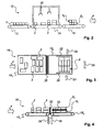
- FIG. 3 schematically shows in plan view how on the discharge conveyor 16 from the stacks 3, the package layers 6 are generated.
- the stack 3 are conveyed in the transport direction 4 against a stop 26. With the stop 26, the stack 3 are dammed so that they are moved together in the transport direction 4 positive pack layers 6.
- the packaged in the transport direction 4 4 merged together packaged layers 6 in the transverse direction 25 to the transport direction 4 by a pair of slides 22 positively.
- the slide pair 22 is moved in the direction of thrust 24 so that a form fit within the package layers 6 is formed both in the transport direction 4 and transversely to the transport direction 4.
- FIG. 4 shows schematically in the side view, as on the outlet conveyor 16 from the stacks 3, the package layers 6 are generated.
- the stack 3 are dammed by the stop 26 so that they are in Transport direction 4 form-fitting package layers 6 1 and 6 2 are merged. So that the package layers 6 1 and 6 2 can be transferred to the second part of the outlet conveyor 16 2 , the stop 26 is sunk in the direction of arrow 28 between the two parts of the outlet conveyor 16. After the package layers 6 1 and 6 2 were transferred to the second part of the outlet conveyor 16 2 , the stop 26 is moved back in the direction of arrow 29, so that more package layers 6 1 and 6 2 , which are supplied to the first part of the outlet conveyor 16 1 can be dammed.
- the packaging layer 4 positive in the transport direction 6 1 and 6 2 are merged with the slide pair 22 positively in the transport direction 4 and transversely to the transport direction 4.
- FIG. 5 schematically shows how the package layers 6 1 and 6 2 are transferred with the slider 30 in the jalousie head 21.
- the transfer takes place in such a way that the slide 30 pushes the bundle layers 6 1 and 6 2 in the direction of transport 4 into the blind head 21.
- the slider 30 is moved back over the second part of the outlet conveyor 16 2 , so that with the second part of the outlet conveyor 16 2 subsequent package layers 6 1 and 6 2 in the shutter head 21st can be pushed.
- FIG. 6 schematically shows how the drum layers 6 1 and 6 2 are transferred to the bracket 32 in the shutter head 21.
- the last stack 3 of layers of packages 6 1 and 6 2 can not be fully inserted with the second part of the exit conveyor 16 2 into the blind head 21, as the second part of the Austaufchers 16 2 does not extend into the shutter head 21st
- the bracket 32 is moved down and pushes the package layers 6 1 and 6 2 completely in the blind head 21.
- the bracket 32 serves to secure the package layers 6 1 and 6 2 in the shutter head 21st
- FIG. 7 schematically shows how the package layers 6 1 and 6 2 are transferred to the bracket 32 and additional Aufroll rollers 34 in the jalousie head 21.
- the package layers 6 1 and 6 2 by the driven Aufroll roller 34th inserted into the shutter head 21.
- the bracket 32 moves the package layers 6 1 and 6 2 as in FIG. 6 described in the shutter head 21 inside.
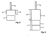
- FIG. 8 shows schematically the structure of a gripper 18 1 for receiving a container 2. With this gripper 18 1 , it is possible to receive a container 2. This is possible essentially by the length 40 of the gripping tools 19.
- FIG. 9 schematically shows the structure of a gripper 18 2 for receiving a stack 3 of two containers 2.
- the length 44 of the gripper tools 19 of the gripper 18 2 is designed such that it can accommodate a stack 3 of at least two containers 2.
Landscapes
- Engineering & Computer Science (AREA)
- Mechanical Engineering (AREA)
- Specific Conveyance Elements (AREA)
- Supplying Of Containers To The Packaging Station (AREA)
- Auxiliary Devices For And Details Of Packaging Control (AREA)
Claims (15)
- Dispositif (10) pour la formation économique de couches de packs (6), avec au moins un convoyeur d'alimentation (12) pour amener les packs (2), au moins un autre convoyeur (14) qui est installé en aval du convoyeur d'alimentation (12) et est affecté à l'au moins un grappin (18) pour le positionnement et/ou la rotation des packs (2), au moins un convoyeur de décharge (16), qui est installé en aval de l'autre convoyeur (14), sur lequel les packs (2) positionnés et/ou tournés peuvent être regroupés avec des moyens correspondants en couches de packs (6) crabotées, caractérisé en ce que, par le au moins un grappin (18), au moins un pack (2) est positionnable et/ou rotatif et, par le au moins un grappin (18), au moins un autre pack (2) peut être déposé avec la même orientation positionné et/ou tourné sur le pack (2), ou en ce que, par le au moins un grappin (18), au moins deux packs (2) sont empilables l'un sur l'autre avec la même orientation en une pile (3) qui peut elle-même être positionnée et/ou tournée par le au moins un grappin (18).
- Dispositif (10) pour la formation économique de couches de packs (6) selon la revendication 1, caractérisé en ce que une butée (26) est disposée entre une première partie du convoyeur de décharge (161) et une deuxième partie du convoyeur de décharge (162), de manière à ce que les packs (2) forment seulement dans le sens de transport (4) au moins deux couches de packs (6) crabotées constituées de piles (3).
- Dispositif (10) pour la formation économique de couches de packs (6) selon la revendication 2, caractérisé en ce que une paire de coulisses (22) est parallèle au sens de transport (4) est affectée à la deuxième partie du convoyeur de décharge (162), de manière à ce que les packs (2) forment dans le sens de transport (4) et transversalement par rapport au sens de transport (4) au moins deux couches de packs (6) crabotées constituées de piles (3).
- Dispositif (10) pour la formation économique de couches de packs (6) selon l'une quelconque des revendications 1 à 3, caractérisé en ce que le au moins un grappin (18) positionne et/ou tourne un pack (2) qui est partie intégrante d'une première couche de packs (61), et en ce que le grappin (18) dépose sur le pack (2) positionné et/ou tourné seulement un autre pack (2) avec la même orientation et, ainsi, forme une pile (3) de deux packs (2).
- Dispositif (10) pour la formation économique de couches de packs (6) selon l'une quelconque des revendications 1 à 3, caractérisé en ce que le au moins un grappin (18) dépose un deuxième pack (2) qui est partie intégrante d'une deuxième couche de packs (62) sur un premier pack (2) avec la même orientation, pack (2) qui est partie intégrante d'une première couche de packs (61), de manière à ce que la pile (3) puisse être positionnée et/ou tournée avec le au moins un grappin (18).
- Dispositif (10) pour la formation économique de couches de packs (6) selon l'une quelconque des revendications 3 à 5, caractérisé en ce que au moins un moyen d'amenée des au moins deux couches de packs (6) empilées et crabotées constituées de piles (3) à un palettiseur (20) est affecté à la deuxième partie du convoyeur de décharge (162), ledit palettiseur (20) étant installé en aval de la deuxième partie du convoyeur de décharge (162).
- Dispositif (10) pour la formation économique de couches de packs (6) selon la revendication 6, caractérisé en ce que le palettiseur (20) comprend au moins une tête de jalousie (21).
- Dispositif (10) pour la formation économique de couches de packs (6) selon la revendication 6, caractérisé en ce que le au moins un moyen d'amenée est une coulisse (30).
- Dispositif (10) pour la formation économique de couches de packs (6) selon les revendications 6 et 7, caractérisé en ce que le au moins un moyen d'amenée est une étrier (32) qui est disposé sur la tête de jalousie (21).
- Procédé pour la formation économique de couches de packs (6), caractérisé par les étapes suivantes :• avec au moins un convoyeur d'alimentation (12), les packs (2) sont amenés en série à au moins un autre convoyeur (14),• sur l'autre convoyeur (14) comportant au moins un grappin (18), au moins un pack (2) est positionné et/ou tourné, et, sur le pack (2) positionné et/ou tourné, au moins un autre pack (2) est déposé avec la même orientation par le au moins un grappin (18), ou en ce que, par le grappin (18), au moins deux packs (2) sont empilés l'un au-dessus de l'autre avec la même orientation en une pile (3), et la pile (3) peut ensuite être positionnée et/ou tournée par le au moins un grappin (18), et• en ce qu'est affecté à l'autre convoyeur (14) au moins un convoyeur de décharge (16) sur lequel les packs (2) positionnés et/ou tournés sont regroupés avec des moyens correspondants en couches de packs (6) crabotées constituées de piles (3).
- Procédé selon la revendication 10, caractérisé en ce que une butée (26) est disposée entre une première partie du convoyeur de décharge (161) et une deuxième partie du convoyeur de décharge (162), butée (26) avec laquelle les packs (2) sont retenus de manière à ce que soient formées seulement dans le sens de transport (4) au moins deux couches de packs (6) crabotées constituées de piles (3).
- Procédé selon la revendication 11, caractérisé en ce que, avec une paire de coulisses (22) qui est parallèle au sens de transport (4) et est affectée à la deuxième partie du convoyeur de décharge (162), les packs (2) sont regroupés dans le sens de transport (4) et transversalement par rapport au sens de transport (4) en au moins deux couches de packs (6) crabotées constituées de piles (3).
- Procédé selon l'une quelconque des revendications 10 à 12, caractérisé en ce que, avec le au moins un grappin (18), un pack (2) qui est partie intégrante d'une première couche de packs (61) est positionné et/ou tourné, et en ce que le grappin (18) dépose sur le pack (2) positionné et/ou tourné seulement un autre pack (2) avec la même orientation afin de former ainsi une pile (3) de deux packs (2).
- Procédé selon l'une quelconque des revendications 10 à 13, caractérisé en ce que, avec le au moins un grappin (18), un deuxième pack (2) qui est partie intégrante d'une deuxième couche de packs (62) est déposé sur un premier pack (2) avec la même orientation, étant donné que le premier pack (2) est partie intégrante d'une première couche de packs (61), et en ce que la pile (3) est positionnée et/ou tournée avec le au moins un grappin (18).
- Procédé selon l'une quelconque des revendications 10 à 14, caractérisé en ce que, avec le au moins un convoyeur de décharge (16), les couches de packs (6) constituées de piles (3) sont amenées à au moins un palettiseur (20).
Applications Claiming Priority (1)
| Application Number | Priority Date | Filing Date | Title |
|---|---|---|---|
| DE102008050395A DE102008050395A1 (de) | 2008-10-02 | 2008-10-02 | Vorrichtung und Verfahren zum ökonomischen Formen von Gebindelagen |
Publications (3)
| Publication Number | Publication Date |
|---|---|
| EP2174895A2 EP2174895A2 (fr) | 2010-04-14 |
| EP2174895A3 EP2174895A3 (fr) | 2011-06-22 |
| EP2174895B1 true EP2174895B1 (fr) | 2012-04-18 |
Family
ID=41268500
Family Applications (1)
| Application Number | Title | Priority Date | Filing Date |
|---|---|---|---|
| EP09158416A Active EP2174895B1 (fr) | 2008-10-02 | 2009-04-22 | Dispositif et procédé économique de formation de couches de conteneurs |
Country Status (4)
| Country | Link |
|---|---|
| US (1) | US8147177B2 (fr) |
| EP (1) | EP2174895B1 (fr) |
| AT (1) | ATE554034T1 (fr) |
| DE (1) | DE102008050395A1 (fr) |
Families Citing this family (22)
| Publication number | Priority date | Publication date | Assignee | Title |
|---|---|---|---|---|
| US9475649B2 (en) | 2010-12-15 | 2016-10-25 | Symbolic, LLC | Pickface builder for storage and retrieval systems |
| JP5803887B2 (ja) * | 2012-12-03 | 2015-11-04 | 株式会社安川電機 | ロボット |
| DE102013103886A1 (de) * | 2013-04-17 | 2014-10-23 | Krones Aktiengesellschaft | Vorrichtung und Verfahren zum Ausbilden einer vordefinierten Formation auf einem Transportband |
| DE102014101722C5 (de) * | 2014-02-12 | 2024-03-07 | Khs Gmbh | Vorrichtung und Verfahren zum Erzeugen von Gebinden aus miteinander verklebten Behältern |
| DE102014224550A1 (de) * | 2014-12-01 | 2016-06-02 | Krones Aktiengesellschaft | Vorrichtung und Verfahren zur Ausrichtung von zu Gruppen zusammengefassten Artikeln und/oder Stückgütern |
| DE102015104324B4 (de) * | 2015-03-23 | 2025-08-14 | Krones Aktiengesellschaft | Verfahren und Vorrichtung zur Handhabung von Artikeln, Stückgütern bzw. Gebinden |
| US9403646B1 (en) * | 2015-05-29 | 2016-08-02 | Columbia Machine, Inc. | Palletizer with configurable diverter and turn lanes for pattern formation |
| DE102016202182A1 (de) * | 2016-02-12 | 2017-08-17 | Krones Aktiengesellschaft | Vorrichtung und Verfahren zum Manipulieren von Stückgütern eines Stückgutstromes |
| DE102016203435A1 (de) * | 2016-03-02 | 2017-09-07 | Krones Aktiengesellschaft | Abschnitt einer Verpackungslinie für Getränkebehältnisse und Verfahren zum Umgang mit Getränkebehältnissen während ihres Transportes entlang einer Verpackungslinie |
| DE102016206650A1 (de) * | 2016-04-20 | 2017-10-26 | Krones Aktiengesellschaft | Verfahren und Vorrichtung zum Umgang mit hintereinander bewegten Stückgütern |
| DE102017111653A1 (de) | 2017-05-29 | 2018-11-29 | Krones Aktiengesellschaft | Vorrichtung und Verfahren zum Umgang mit in mindestens einer Reihe von hintereinander bewegten Stückgütern |
| DE102017212157A1 (de) * | 2017-07-14 | 2019-01-17 | Krones Aktiengesellschaft | Verfahren und Vorrichtung zur Handhabung von Stückgütern, Artikeln und/oder Gebinden |
| DE102017212158A1 (de) * | 2017-07-14 | 2019-01-17 | Krones Aktiengesellschaft | Verfahren und Vorrichtung zur Handhabung von Stückgütern, Artikeln und/oder Gebinden |
| DE102018115739A1 (de) * | 2018-06-29 | 2020-01-02 | Krones Aktiengesellschaft | Verfahren zum Stapeln von Artikeln und/oder Stückgütern und Stapelbildungsvorrichtung |
| JP7415825B2 (ja) * | 2020-06-30 | 2024-01-17 | 株式会社ダイフク | 物品処理装置 |
| JP7415826B2 (ja) * | 2020-06-30 | 2024-01-17 | 株式会社ダイフク | 物品処理装置 |
| IT202000025492A1 (it) * | 2020-10-27 | 2022-04-27 | Cft Robotics S R L | Metodo e macchina integrata per il confezionamento e l’impilamento di imballaggi |
| US11760582B2 (en) | 2020-11-03 | 2023-09-19 | Ulma Packaging, S. Coop. | Product packaging installation |
| DE102021113060A1 (de) * | 2021-05-20 | 2022-11-24 | Khs Gmbh | Vorrichtung und Verfahren zur Handhabung und/oder Gruppierung von Stückgütern |
| DE102021114998A1 (de) | 2021-06-10 | 2022-12-15 | Krones Aktiengesellschaft | Verfahren zur Erstellung von Gebindelagen, Vorrichtung zur Erstellung von Gebindelagen und Gebindelage |
| CN114394417A (zh) * | 2021-12-23 | 2022-04-26 | 盐城雄鹰精密机械有限公司 | 一种地板包码垛装置 |
| DE102022114569A1 (de) | 2022-06-09 | 2023-12-14 | Krones Aktiengesellschaft | System und Verfahren zum Gruppieren und Palettieren von Gebinden |
Family Cites Families (16)
| Publication number | Priority date | Publication date | Assignee | Title |
|---|---|---|---|---|
| US3442400A (en) * | 1967-03-02 | 1969-05-06 | Alvey Conveyor Mfg Co | Carton palletizing apparatus |
| US3587876A (en) | 1968-11-25 | 1971-06-28 | Power Curve Conveyor Co | Pallet-loading apparatus |
| US3587878A (en) * | 1969-03-24 | 1971-06-28 | Autolift Garage Ab | Sectional component endless parking elevator |
| US3667622A (en) * | 1970-08-17 | 1972-06-06 | Keller & Co C | Method of and means for stacking moulded articles in groups |
| DE8206793U1 (de) * | 1982-03-11 | 1985-03-28 | Deta-Akkumulatorenwerk Gmbh, 3422 Bad Lauterberg | Vorrichtung zur bildung von stapeln von akkumulatorplatten |
| US4641271A (en) * | 1983-11-09 | 1987-02-03 | Hitachi, Ltd. | Piling planning method and piling system of cargoes by palletizing robot |
| FR2738559B1 (fr) | 1995-09-07 | 1997-11-14 | Newtec Palettisation | Dispositif d'empilage des couches sur une palette et dispositif de palettisation |
| EP1046598A1 (fr) | 1999-04-20 | 2000-10-25 | Kisters, Inc | Dispositif pour la fabrication de couches palettisables d'ensembles d'emballages |
| FR2819498B1 (fr) * | 2001-01-16 | 2003-04-25 | Newtec Palettisation | Procede et systeme pour former automatiquement et en continu des couches de lots d'unites de vente avant de les empiler sur une palette |
| DE20119851U1 (de) | 2001-12-07 | 2003-04-10 | AUTEFA Automation GmbH, 86316 Friedberg | Vorrichtung zur Reihenbildung von Packgütern |
| DE10219129B4 (de) | 2002-04-29 | 2004-05-27 | Schaefer Förderanlagen- und Maschinenbau GmbH | Vorrichtung zum Drehen und Verteilen oder Zusammenführen von Packs |
| US20040223839A1 (en) * | 2003-05-09 | 2004-11-11 | Simkowski Donald J. | Apparatus and method for product palletizing |
| AU2004201709A1 (en) * | 2004-04-23 | 2005-11-10 | Foodmach Pty Ltd | Materials handling system |
| DE202005015268U1 (de) * | 2005-09-27 | 2007-02-08 | Krones Ag | Vorrichtung zum Handhaben von Gegenständen |
| DE202005015887U1 (de) * | 2005-10-07 | 2006-05-11 | Krones Ag | Palettenkommissioniermaschine |
| ITBO20060560A1 (it) * | 2006-07-26 | 2008-01-27 | Tissue Logistics Solutions S P A | Unita' per la preparazione di gruppi di prodotti in strati da pallettizzare. |
-
2008
- 2008-10-02 DE DE102008050395A patent/DE102008050395A1/de not_active Withdrawn
-
2009
- 2009-04-22 AT AT09158416T patent/ATE554034T1/de active
- 2009-04-22 EP EP09158416A patent/EP2174895B1/fr active Active
- 2009-09-08 US US12/584,587 patent/US8147177B2/en active Active
Also Published As
| Publication number | Publication date |
|---|---|
| US20100083622A1 (en) | 2010-04-08 |
| EP2174895A2 (fr) | 2010-04-14 |
| US8147177B2 (en) | 2012-04-03 |
| DE102008050395A1 (de) | 2010-04-08 |
| EP2174895A3 (fr) | 2011-06-22 |
| ATE554034T1 (de) | 2012-05-15 |
Similar Documents
| Publication | Publication Date | Title |
|---|---|---|
| EP2174895B1 (fr) | Dispositif et procédé économique de formation de couches de conteneurs | |
| DE2702041C3 (de) | Vorrichtung zum wahlweisen Aufteilen einer Reihe von einzelnen gewickelten Rollen aus Folien o.dgl. von einem Zuförderer über einen Zwischenförderer an eine Anzahl von Verteilförderern | |
| EP2313332B1 (fr) | Dispositif et procede pour le regroupement de lots pour une machine d'emballage | |
| EP0847949B1 (fr) | Dispositif pour empiler un chant de feuilles imprimées | |
| EP2881332B1 (fr) | Dispositif de transport de produits | |
| DE102013113754A1 (de) | Verfahren zur Bildung von Gebinden und zu deren Palettierung sowie Förder- und Handhabungsvorrichtung für Artikel und Gebinde | |
| EP3153025A2 (fr) | Dispositif destine au traitement individuel de saucisse | |
| DE2037911A1 (de) | Verfahren zum Aufstapeln von Vorzugs weise zusammengefalteten Schachteln o dgl und Vorrichtung zur Durchfuhrung des Ver fahrens | |
| EP2266901B1 (fr) | Dispositif et procédé de chargement d'articles pour une unité de traitement | |
| DE102018116679B4 (de) | Anlage zum Magazinieren von Trennleisten, Anlage zum Binden von Brettstapeln und Magazin | |
| EP2133271A1 (fr) | Dispositif et procédé de transmission de marchandises sur un système de transport de marchandises ou sur un dispositif de stockage | |
| WO2023016693A1 (fr) | Appareil et procédé de fabrication d'emballages composites carton/plastique remplis | |
| EP3984923A1 (fr) | Procédé d'alimentation en pièces allongées en bois, en matière plastique et analogues, ainsi qu'installation de mise en uvre du procédé | |
| EP1029705B1 (fr) | Méthode pour assembler des produits imprimés | |
| EP2133293A1 (fr) | Dispositif de transmission de marchandises sur un système de transport de marchandises ou sur un dispositif de stockage | |
| EP0583218B1 (fr) | Procédé et dispositif pour transporter des paquets tubulaires de produits imprimés et leur assemblage comme unités d'expédition | |
| DE69412178T2 (de) | Apparat zur Behandlung von Lagen | |
| EP1293453B1 (fr) | Dispositif pour la fabrication de couches palettisables | |
| DE69900899T2 (de) | Schneckenförderer für Beipackzettel und ähnliche Gegenstände | |
| EP1500520A2 (fr) | Procédé et dispositif pour le dépôt en position plate des livres | |
| EP2383214B1 (fr) | Dispositif d'assemblage | |
| DE19623307A1 (de) | Vorrichtung zum Verarbeiten von Druckereiprodukten | |
| EP3999455A1 (fr) | Dispositif de palettisation et procédé de palettisation de charges isolées | |
| DE102021202108A1 (de) | Verfahren und Vorrichtung zum Verkleben mehrerer für ein jeweiliges Gebinde vorgesehener Artikel | |
| DE3736610A1 (de) | Vorrichtung zum beliebigen gruppenweisen transport von beuteln |
Legal Events
| Date | Code | Title | Description |
|---|---|---|---|
| PUAI | Public reference made under article 153(3) epc to a published international application that has entered the european phase |
Free format text: ORIGINAL CODE: 0009012 |
|
| AK | Designated contracting states |
Kind code of ref document: A2 Designated state(s): AT BE BG CH CY CZ DE DK EE ES FI FR GB GR HR HU IE IS IT LI LT LU LV MC MK MT NL NO PL PT RO SE SI SK TR |
|
| PUAL | Search report despatched |
Free format text: ORIGINAL CODE: 0009013 |
|
| AK | Designated contracting states |
Kind code of ref document: A3 Designated state(s): AT BE BG CH CY CZ DE DK EE ES FI FR GB GR HR HU IE IS IT LI LT LU LV MC MK MT NL NO PL PT RO SE SI SK TR |
|
| 17P | Request for examination filed |
Effective date: 20110810 |
|
| GRAP | Despatch of communication of intention to grant a patent |
Free format text: ORIGINAL CODE: EPIDOSNIGR1 |
|
| GRAS | Grant fee paid |
Free format text: ORIGINAL CODE: EPIDOSNIGR3 |
|
| GRAA | (expected) grant |
Free format text: ORIGINAL CODE: 0009210 |
|
| AK | Designated contracting states |
Kind code of ref document: B1 Designated state(s): AT BE BG CH CY CZ DE DK EE ES FI FR GB GR HR HU IE IS IT LI LT LU LV MC MK MT NL NO PL PT RO SE SI SK TR |
|
| REG | Reference to a national code |
Ref country code: GB Ref legal event code: FG4D Free format text: NOT ENGLISH |
|
| REG | Reference to a national code |
Ref country code: CH Ref legal event code: EP |
|
| REG | Reference to a national code |
Ref country code: IE Ref legal event code: FG4D Free format text: LANGUAGE OF EP DOCUMENT: GERMAN |
|
| REG | Reference to a national code |
Ref country code: AT Ref legal event code: REF Ref document number: 554034 Country of ref document: AT Kind code of ref document: T Effective date: 20120515 |
|
| REG | Reference to a national code |
Ref country code: DE Ref legal event code: R096 Ref document number: 502009003284 Country of ref document: DE Effective date: 20120614 |
|
| REG | Reference to a national code |
Ref country code: NL Ref legal event code: VDEP Effective date: 20120418 |
|
| LTIE | Lt: invalidation of european patent or patent extension |
Effective date: 20120418 |
|
| BERE | Be: lapsed |
Owner name: KRONES A.G. Effective date: 20120430 |
|
| PG25 | Lapsed in a contracting state [announced via postgrant information from national office to epo] |
Ref country code: CY Free format text: LAPSE BECAUSE OF FAILURE TO SUBMIT A TRANSLATION OF THE DESCRIPTION OR TO PAY THE FEE WITHIN THE PRESCRIBED TIME-LIMIT Effective date: 20120418 Ref country code: LT Free format text: LAPSE BECAUSE OF FAILURE TO SUBMIT A TRANSLATION OF THE DESCRIPTION OR TO PAY THE FEE WITHIN THE PRESCRIBED TIME-LIMIT Effective date: 20120418 Ref country code: PL Free format text: LAPSE BECAUSE OF FAILURE TO SUBMIT A TRANSLATION OF THE DESCRIPTION OR TO PAY THE FEE WITHIN THE PRESCRIBED TIME-LIMIT Effective date: 20120418 Ref country code: NO Free format text: LAPSE BECAUSE OF FAILURE TO SUBMIT A TRANSLATION OF THE DESCRIPTION OR TO PAY THE FEE WITHIN THE PRESCRIBED TIME-LIMIT Effective date: 20120718 Ref country code: IS Free format text: LAPSE BECAUSE OF FAILURE TO SUBMIT A TRANSLATION OF THE DESCRIPTION OR TO PAY THE FEE WITHIN THE PRESCRIBED TIME-LIMIT Effective date: 20120818 Ref country code: FI Free format text: LAPSE BECAUSE OF FAILURE TO SUBMIT A TRANSLATION OF THE DESCRIPTION OR TO PAY THE FEE WITHIN THE PRESCRIBED TIME-LIMIT Effective date: 20120418 Ref country code: SE Free format text: LAPSE BECAUSE OF FAILURE TO SUBMIT A TRANSLATION OF THE DESCRIPTION OR TO PAY THE FEE WITHIN THE PRESCRIBED TIME-LIMIT Effective date: 20120418 |
|
| PG25 | Lapsed in a contracting state [announced via postgrant information from national office to epo] |
Ref country code: PT Free format text: LAPSE BECAUSE OF FAILURE TO SUBMIT A TRANSLATION OF THE DESCRIPTION OR TO PAY THE FEE WITHIN THE PRESCRIBED TIME-LIMIT Effective date: 20120820 Ref country code: SI Free format text: LAPSE BECAUSE OF FAILURE TO SUBMIT A TRANSLATION OF THE DESCRIPTION OR TO PAY THE FEE WITHIN THE PRESCRIBED TIME-LIMIT Effective date: 20120418 Ref country code: GR Free format text: LAPSE BECAUSE OF FAILURE TO SUBMIT A TRANSLATION OF THE DESCRIPTION OR TO PAY THE FEE WITHIN THE PRESCRIBED TIME-LIMIT Effective date: 20120719 Ref country code: HR Free format text: LAPSE BECAUSE OF FAILURE TO SUBMIT A TRANSLATION OF THE DESCRIPTION OR TO PAY THE FEE WITHIN THE PRESCRIBED TIME-LIMIT Effective date: 20120418 Ref country code: MC Free format text: LAPSE BECAUSE OF NON-PAYMENT OF DUE FEES Effective date: 20120430 Ref country code: LV Free format text: LAPSE BECAUSE OF FAILURE TO SUBMIT A TRANSLATION OF THE DESCRIPTION OR TO PAY THE FEE WITHIN THE PRESCRIBED TIME-LIMIT Effective date: 20120418 |
|
| REG | Reference to a national code |
Ref country code: IE Ref legal event code: MM4A |
|
| PG25 | Lapsed in a contracting state [announced via postgrant information from national office to epo] |
Ref country code: CZ Free format text: LAPSE BECAUSE OF FAILURE TO SUBMIT A TRANSLATION OF THE DESCRIPTION OR TO PAY THE FEE WITHIN THE PRESCRIBED TIME-LIMIT Effective date: 20120418 Ref country code: DK Free format text: LAPSE BECAUSE OF FAILURE TO SUBMIT A TRANSLATION OF THE DESCRIPTION OR TO PAY THE FEE WITHIN THE PRESCRIBED TIME-LIMIT Effective date: 20120418 Ref country code: SK Free format text: LAPSE BECAUSE OF FAILURE TO SUBMIT A TRANSLATION OF THE DESCRIPTION OR TO PAY THE FEE WITHIN THE PRESCRIBED TIME-LIMIT Effective date: 20120418 Ref country code: NL Free format text: LAPSE BECAUSE OF FAILURE TO SUBMIT A TRANSLATION OF THE DESCRIPTION OR TO PAY THE FEE WITHIN THE PRESCRIBED TIME-LIMIT Effective date: 20120418 Ref country code: BE Free format text: LAPSE BECAUSE OF NON-PAYMENT OF DUE FEES Effective date: 20120430 Ref country code: IE Free format text: LAPSE BECAUSE OF NON-PAYMENT OF DUE FEES Effective date: 20120422 Ref country code: EE Free format text: LAPSE BECAUSE OF FAILURE TO SUBMIT A TRANSLATION OF THE DESCRIPTION OR TO PAY THE FEE WITHIN THE PRESCRIBED TIME-LIMIT Effective date: 20120418 Ref country code: RO Free format text: LAPSE BECAUSE OF FAILURE TO SUBMIT A TRANSLATION OF THE DESCRIPTION OR TO PAY THE FEE WITHIN THE PRESCRIBED TIME-LIMIT Effective date: 20120418 |
|
| PLBE | No opposition filed within time limit |
Free format text: ORIGINAL CODE: 0009261 |
|
| STAA | Information on the status of an ep patent application or granted ep patent |
Free format text: STATUS: NO OPPOSITION FILED WITHIN TIME LIMIT |
|
| PG25 | Lapsed in a contracting state [announced via postgrant information from national office to epo] |
Ref country code: MK Free format text: LAPSE BECAUSE OF FAILURE TO SUBMIT A TRANSLATION OF THE DESCRIPTION OR TO PAY THE FEE WITHIN THE PRESCRIBED TIME-LIMIT Effective date: 20120418 |
|
| 26N | No opposition filed |
Effective date: 20130121 |
|
| PG25 | Lapsed in a contracting state [announced via postgrant information from national office to epo] |
Ref country code: ES Free format text: LAPSE BECAUSE OF FAILURE TO SUBMIT A TRANSLATION OF THE DESCRIPTION OR TO PAY THE FEE WITHIN THE PRESCRIBED TIME-LIMIT Effective date: 20120729 |
|
| REG | Reference to a national code |
Ref country code: DE Ref legal event code: R097 Ref document number: 502009003284 Country of ref document: DE Effective date: 20130121 |
|
| PG25 | Lapsed in a contracting state [announced via postgrant information from national office to epo] |
Ref country code: MT Free format text: LAPSE BECAUSE OF FAILURE TO SUBMIT A TRANSLATION OF THE DESCRIPTION OR TO PAY THE FEE WITHIN THE PRESCRIBED TIME-LIMIT Effective date: 20120418 Ref country code: BG Free format text: LAPSE BECAUSE OF FAILURE TO SUBMIT A TRANSLATION OF THE DESCRIPTION OR TO PAY THE FEE WITHIN THE PRESCRIBED TIME-LIMIT Effective date: 20120718 |
|
| REG | Reference to a national code |
Ref country code: CH Ref legal event code: PL |
|
| GBPC | Gb: european patent ceased through non-payment of renewal fee |
Effective date: 20130422 |
|
| PG25 | Lapsed in a contracting state [announced via postgrant information from national office to epo] |
Ref country code: CH Free format text: LAPSE BECAUSE OF NON-PAYMENT OF DUE FEES Effective date: 20130430 Ref country code: GB Free format text: LAPSE BECAUSE OF NON-PAYMENT OF DUE FEES Effective date: 20130422 Ref country code: LI Free format text: LAPSE BECAUSE OF NON-PAYMENT OF DUE FEES Effective date: 20130430 |
|
| PG25 | Lapsed in a contracting state [announced via postgrant information from national office to epo] |
Ref country code: TR Free format text: LAPSE BECAUSE OF FAILURE TO SUBMIT A TRANSLATION OF THE DESCRIPTION OR TO PAY THE FEE WITHIN THE PRESCRIBED TIME-LIMIT Effective date: 20120418 |
|
| PG25 | Lapsed in a contracting state [announced via postgrant information from national office to epo] |
Ref country code: LU Free format text: LAPSE BECAUSE OF NON-PAYMENT OF DUE FEES Effective date: 20120422 |
|
| PG25 | Lapsed in a contracting state [announced via postgrant information from national office to epo] |
Ref country code: HU Free format text: LAPSE BECAUSE OF FAILURE TO SUBMIT A TRANSLATION OF THE DESCRIPTION OR TO PAY THE FEE WITHIN THE PRESCRIBED TIME-LIMIT Effective date: 20090422 |
|
| REG | Reference to a national code |
Ref country code: FR Ref legal event code: PLFP Year of fee payment: 7 |
|
| REG | Reference to a national code |
Ref country code: AT Ref legal event code: MM01 Ref document number: 554034 Country of ref document: AT Kind code of ref document: T Effective date: 20140422 |
|
| PG25 | Lapsed in a contracting state [announced via postgrant information from national office to epo] |
Ref country code: AT Free format text: LAPSE BECAUSE OF NON-PAYMENT OF DUE FEES Effective date: 20140422 |
|
| REG | Reference to a national code |
Ref country code: FR Ref legal event code: PLFP Year of fee payment: 8 |
|
| REG | Reference to a national code |
Ref country code: FR Ref legal event code: PLFP Year of fee payment: 9 |
|
| REG | Reference to a national code |
Ref country code: FR Ref legal event code: PLFP Year of fee payment: 10 |
|
| P01 | Opt-out of the competence of the unified patent court (upc) registered |
Effective date: 20230523 |
|
| PGFP | Annual fee paid to national office [announced via postgrant information from national office to epo] |
Ref country code: DE Payment date: 20250305 Year of fee payment: 17 |
|
| PGFP | Annual fee paid to national office [announced via postgrant information from national office to epo] |
Ref country code: IT Payment date: 20260320 Year of fee payment: 18 |
|
| PGFP | Annual fee paid to national office [announced via postgrant information from national office to epo] |
Ref country code: FR Payment date: 20260309 Year of fee payment: 18 |