EP2175143A1 - Hydraulische Antriebsvorrichtung für Tore und dergleichen - Google Patents
Hydraulische Antriebsvorrichtung für Tore und dergleichen Download PDFInfo
- Publication number
- EP2175143A1 EP2175143A1 EP09170250A EP09170250A EP2175143A1 EP 2175143 A1 EP2175143 A1 EP 2175143A1 EP 09170250 A EP09170250 A EP 09170250A EP 09170250 A EP09170250 A EP 09170250A EP 2175143 A1 EP2175143 A1 EP 2175143A1
- Authority
- EP
- European Patent Office
- Prior art keywords
- circuit
- stem
- reservoir
- piston
- actuation
- Prior art date
- Legal status (The legal status is an assumption and is not a legal conclusion. Google has not performed a legal analysis and makes no representation as to the accuracy of the status listed.)
- Withdrawn
Links
- 238000011144 upstream manufacturing Methods 0.000 claims description 6
- 230000033001 locomotion Effects 0.000 claims description 4
- 239000012530 fluid Substances 0.000 claims description 2
- 230000002441 reversible effect Effects 0.000 claims description 2
- 238000004891 communication Methods 0.000 description 5
- 230000001788 irregular Effects 0.000 description 3
- 238000012986 modification Methods 0.000 description 3
- 230000004048 modification Effects 0.000 description 3
- 238000009434 installation Methods 0.000 description 2
- 206010013647 Drowning Diseases 0.000 description 1
- 230000000903 blocking effect Effects 0.000 description 1
- 238000010276 construction Methods 0.000 description 1
- 238000007599 discharging Methods 0.000 description 1
- 238000006073 displacement reaction Methods 0.000 description 1
- 230000005662 electromechanics Effects 0.000 description 1
- 239000000463 material Substances 0.000 description 1
- 238000000034 method Methods 0.000 description 1
- 238000007789 sealing Methods 0.000 description 1
Images




Classifications
-
- F—MECHANICAL ENGINEERING; LIGHTING; HEATING; WEAPONS; BLASTING
- F15—FLUID-PRESSURE ACTUATORS; HYDRAULICS OR PNEUMATICS IN GENERAL
- F15B—SYSTEMS ACTING BY MEANS OF FLUIDS IN GENERAL; FLUID-PRESSURE ACTUATORS, e.g. SERVOMOTORS; DETAILS OF FLUID-PRESSURE SYSTEMS, NOT OTHERWISE PROVIDED FOR
- F15B7/00—Systems in which the movement produced is definitely related to the output of a volumetric pump; Telemotors
- F15B7/005—With rotary or crank input
- F15B7/006—Rotary pump input
-
- E—FIXED CONSTRUCTIONS
- E05—LOCKS; KEYS; WINDOW OR DOOR FITTINGS; SAFES
- E05F—DEVICES FOR MOVING WINGS INTO OPEN OR CLOSED POSITION; CHECKS FOR WINGS; WING FITTINGS NOT OTHERWISE PROVIDED FOR, CONCERNED WITH THE FUNCTIONING OF THE WING
- E05F15/00—Power-operated mechanisms for wings
- E05F15/50—Power-operated mechanisms for wings using fluid-pressure actuators
- E05F15/53—Power-operated mechanisms for wings using fluid-pressure actuators for swinging wings
-
- E—FIXED CONSTRUCTIONS
- E05—LOCKS; KEYS; WINDOW OR DOOR FITTINGS; SAFES
- E05Y—INDEXING SCHEME ASSOCIATED WITH SUBCLASSES E05D AND E05F, RELATING TO CONSTRUCTION ELEMENTS, ELECTRIC CONTROL, POWER SUPPLY, POWER SIGNAL OR TRANSMISSION, USER INTERFACES, MOUNTING OR COUPLING, DETAILS, ACCESSORIES, AUXILIARY OPERATIONS NOT OTHERWISE PROVIDED FOR, APPLICATION THEREOF
- E05Y2900/00—Application of doors, windows, wings or fittings thereof
- E05Y2900/40—Application of doors, windows, wings or fittings thereof for gates
-
- F—MECHANICAL ENGINEERING; LIGHTING; HEATING; WEAPONS; BLASTING
- F15—FLUID-PRESSURE ACTUATORS; HYDRAULICS OR PNEUMATICS IN GENERAL
- F15B—SYSTEMS ACTING BY MEANS OF FLUIDS IN GENERAL; FLUID-PRESSURE ACTUATORS, e.g. SERVOMOTORS; DETAILS OF FLUID-PRESSURE SYSTEMS, NOT OTHERWISE PROVIDED FOR
- F15B2211/00—Circuits for servomotor systems
- F15B2211/20—Fluid pressure source, e.g. accumulator or variable axial piston pump
- F15B2211/205—Systems with pumps
- F15B2211/2053—Type of pump
- F15B2211/20561—Type of pump reversible
-
- F—MECHANICAL ENGINEERING; LIGHTING; HEATING; WEAPONS; BLASTING
- F15—FLUID-PRESSURE ACTUATORS; HYDRAULICS OR PNEUMATICS IN GENERAL
- F15B—SYSTEMS ACTING BY MEANS OF FLUIDS IN GENERAL; FLUID-PRESSURE ACTUATORS, e.g. SERVOMOTORS; DETAILS OF FLUID-PRESSURE SYSTEMS, NOT OTHERWISE PROVIDED FOR
- F15B2211/00—Circuits for servomotor systems
- F15B2211/60—Circuit components or control therefor
- F15B2211/61—Secondary circuits
- F15B2211/613—Feeding circuits
-
- F—MECHANICAL ENGINEERING; LIGHTING; HEATING; WEAPONS; BLASTING
- F15—FLUID-PRESSURE ACTUATORS; HYDRAULICS OR PNEUMATICS IN GENERAL
- F15B—SYSTEMS ACTING BY MEANS OF FLUIDS IN GENERAL; FLUID-PRESSURE ACTUATORS, e.g. SERVOMOTORS; DETAILS OF FLUID-PRESSURE SYSTEMS, NOT OTHERWISE PROVIDED FOR
- F15B2211/00—Circuits for servomotor systems
- F15B2211/70—Output members, e.g. hydraulic motors or cylinders or control therefor
- F15B2211/785—Compensation of the difference in flow rate in closed fluid circuits using differential actuators
Definitions
- the adjustment of the thrust and traction dispensed by the piston is normally carried out through two by-pass valves, one for each of the two manoeuvre directions (opening and closing).
- the maximum thrust or traction force is set, in general, during the first installation, through two screws which can be accessed outside the oil distributor of the actuator. If the thrust or traction force limit is exceeded, the by-pass valves open and allow oil to flow parallel to the discharge valves from the circuit to the reservoir. In this situation the stem does not move any further, thus limiting the force transmitted to the gate or door.
- the aforementioned method has been used for decades in industry since it is effective and reliable, but it is not generally precise enough to limit the force acting upon an obstacle on its trajectory, pursuant to the safety regulations in force.
- an actuator with a double-acting piston uses a direct current motor, particularly if there are also no over-pressure valves, it can cause the opening manoeuvres to have problems of regularity, as observed in practice and described for example in the document EP-A-1832756 .
- the difference in volume between the two oil expansion chambers, due to the presence of the gate actuation stem in one of the two expansion chambers means there is an excessive difference between the opening speed and the closing speed.
- the useful volume of the expansion chamber in the return step of the stem which corresponds to the opening manoeuvre of the gate wing, is always less than the volume of the expansion chamber during the exit step of the stem, or rather, the closing step of the gate wing. The difference is given by the volume of the part of stem inside the expansion cylinder.
- the oil circulation pump in the circuit is a volumetric pump, the flow rate in the two operation directions (opening and closing), is practically constant and in any case, in proportion to the rotation speed of the pump.
- the circuit is made as follows: for each operative mode (opening and closing) there is a valve for discharging from the circuit to the expansion chamber, parallel to a by-pass valve from the circuit to the reservoir, the opening of which is controlled by the pressure upstream of the valve itself.
- a high load applied on the actuation stem in the direction opposite to its movement, opens the by-pass valve, which makes part of the flow rate runoff from the circuit downstream of the pump towards the reservoir.
- the opening manoeuvre is consequently irregular and slow with respect to the closing manoeuvre; on the other hand, by adjusting the by-pass valve which allows it to open, a substantial part of flow rate dispensed by the pump remains not used and is sent to the reservoir.
- the limitation of the thrust of the piston is obtained by limiting the torque of the electric motor which actuates the pump and therefore there are no over-pressure valves, there are the same operative problems described above for systems in which the over-pressure valves are completely closed.
- the opening of the circuit towards the reservoir is controlled at the same moment in which the two oil circulation control valves open in order to ensure the flow rate in the circuit in the direction from the chamber without the stem, to the chamber with the stem.
- a duct puts the circuit upstream of the pump on the side of the cylinder without the stem into communication with the reservoir and allows the flow rate to be partialized through a flow of excess oil upstream of the circulation pump, but keeping the geometry of the inlet valves unchanged.
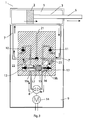
- the gate actuation piston 2 slides in the cylinder 3 separating it into two expansion chambers 4 and 5 of the oil provided by the circuit 7.
- the piston 2 acts upon a stem 6 passing inside the volume 5 in outlet from the right bulkhead of the cylinder 3 towards the fixing brackets of the gate wing.
- the oil is let into the two expansion chambers 4 and 5, through the two discharge valves (12 and 13, respectively), by the reversible volumetric circulation pump 8, actuated by the motor 14.
- the circuit is in turn connected to a compensation reservoir 9, through two inlet valves 10 and 11, one for each branch of the circuit.
- the piston 2 actuates the stem 6 in the direction out from the chamber 5.
- the oil circulates after the two discharge valves 12 and 13 are opened.
- the start up of the pump according to the direction which goes from the chamber 5 to the chamber 4, causes an over-pressure in the volume 19a which, simultaneously, opens the valve 12 and, through the displacement of the small piston 15 and of its pin 16b, opens the valve 19b.
- the supply circuit 7 is completely opened and a flow rate of oil goes from the expansion chamber 5 to the expansion chamber 4. Since the flow rate let in by the chamber 5 through the circuit 7 is in shortfall, the inlet valve 11 from the reservoir 9 to the circuit section upstream of the pump, or rather, in the volume 19b represented in fig.1 , opens.
- the piston 2 actuates the stem 6 according to the entrance direction of the chamber 5.
- the oil circulates after the two valves 12 and 13 are simultaneously opened.
- the actuation pump according to the direction which goes from the chamber 4 to the chamber 5, causes an over-pressure in the volume 19b which, simultaneously, opens the valve 13 and through the small piston 15 and the pin 16a, opens the valve 19a.
- the supply circuit opens and determines the oil circulation from the expansion chamber 4 to the expansion chamber 5.
- a release tap 22 is also represented which, through an auxiliary duct 23, positioned parallel to the main circuit 7, puts the two expansion chambers into communication and allows a manual emergency manoeuvre to be carried out.
- the small control piston 15 represented in fig. 2 which slides inside the cylinder 19 and separates the two circuit branches, is modified in order to obtain a circular groove 18 on the outer surface of the cylinder, at the ends of which there are two pins for actuating the balls of the two valves 12 and 13, said circular groove 18 allowing the excess oil to runoff from the circuit to the reservoir, which only happens during the return step of the stem.
- fig. 2 the small control piston 15 represented in fig. 2 , which slides inside the cylinder 19 and separates the two circuit branches, is modified in order to obtain a circular groove 18 on the outer surface of the cylinder, at the ends of which there are two pins for actuating the balls of the two valves 12 and 13, said circular groove 18 allowing the excess oil to runoff from the circuit to the reservoir, which only happens during the return step of the stem.
- the small piston 15 has two grooves formed on its outer surface, the first of which (ref. 25) constitutes a seat for a sealing gasket, whereas in the other (ref. 18) some holes 20 are formed to put the volume 19a into communication with the groove itself.
- the over-pressure acting in 19b pushes the small piston 15 and the door in such a position as to open a duct 17 made directly in the head of the distributor 24 and communicating with the reservoir 9.
- the geometry described for the small piston 15 and the position of the duct entrance 17 are such that during the gate opening manoeuvre, or rather the return of the stem into the cylinder, the part of excess fluid, determined by the presence of the stem 6, can be drawn towards the compensation reservoir 9.
- the sections of duct 17 and of the through holes 20 formed in the groove 18 of the small piston 15 are sized so as to ensure a flow rate which is sufficient to compensate for the difference in volume between the chamber 4 and 5 inside the cylinder 3 during the opening manoeuvre. Otherwise, during the closing manoeuvre, i.e., during the exit of the stem from the cylinder, the small piston 5 slides in the opposite direction blocking the duct 17.
- the geometry of the small piston 15 and the position of the duct entrance 17 thus allow the communication between the circuit and reservoir along the duct 17 to alternatively open and close.
- the excess flow rate passes from the cylinder to the reservoir in order to compensate the presence of the stem 6, whereas during the closing manoeuvre and of exit of the stem, the compensation of the flow rate shortfall is carried out through the opening of the inlet valve 11, when the duct 17 is completely closed.
- the aforementioned embodiment does not imply any modification of the inlet valves, whereas a modest and suitable modification of the small piston 15 and of the distributor 24 is sufficient to obtain the compensation of the volume of oil in just the return direction of the stem 6.
- a variant of the solution just described uses a by-pass duct 21 which, in per se known ways, is normally already in the distribution head of the oil. Indeed, as it has already been described and represented in fig. 1 , in the distributor 24 there is an auxiliary circuit 23, positioned parallel to the circuit 7 to allow a manual release manoeuvre to be carried out.
- the duct 21, made inside the distributor 24, branching off from the circuit 23, has the function of allowing compensation of the flow rate during the manual and emergency release.
- the duct 21 makes the flow rate of the excess oil runoff into the reservoir; vice versa, in the direction of exit of the stem, the duct takes in the flow rate shortfall directly from the reservoir.
- the tap 22 is made so that its opening puts the duct 21 into communication with the circuit 23.
Landscapes
- Engineering & Computer Science (AREA)
- Physics & Mathematics (AREA)
- Fluid Mechanics (AREA)
- Mechanical Engineering (AREA)
- General Engineering & Computer Science (AREA)
- Fluid-Pressure Circuits (AREA)
- Injection Moulding Of Plastics Or The Like (AREA)
Applications Claiming Priority (1)
| Application Number | Priority Date | Filing Date | Title |
|---|---|---|---|
| IT000233A ITVI20080233A1 (it) | 2008-10-08 | 2008-10-08 | Sistema idraulico di azionamento per la movimentazione di cancelli motorizzati e simili |
Publications (1)
| Publication Number | Publication Date |
|---|---|
| EP2175143A1 true EP2175143A1 (de) | 2010-04-14 |
Family
ID=41179529
Family Applications (1)
| Application Number | Title | Priority Date | Filing Date |
|---|---|---|---|
| EP09170250A Withdrawn EP2175143A1 (de) | 2008-10-08 | 2009-09-15 | Hydraulische Antriebsvorrichtung für Tore und dergleichen |
Country Status (2)
| Country | Link |
|---|---|
| EP (1) | EP2175143A1 (de) |
| IT (1) | ITVI20080233A1 (de) |
Citations (3)
| Publication number | Priority date | Publication date | Assignee | Title |
|---|---|---|---|---|
| US4343153A (en) * | 1980-03-21 | 1982-08-10 | Eltra Corporation | Anti-supercharge pressure valve |
| US20070199437A1 (en) * | 2006-02-27 | 2007-08-30 | Yoshitake Sakai | Operate check valve and hydraulic driving unit |
| EP1832756A2 (de) | 2006-03-10 | 2007-09-12 | FAAC S.p.A. | Betätigungseinrichtung mit doppeltwirkendem Zylinder zum Bewegen eines Tors |
-
2008
- 2008-10-08 IT IT000233A patent/ITVI20080233A1/it unknown
-
2009
- 2009-09-15 EP EP09170250A patent/EP2175143A1/de not_active Withdrawn
Patent Citations (3)
| Publication number | Priority date | Publication date | Assignee | Title |
|---|---|---|---|---|
| US4343153A (en) * | 1980-03-21 | 1982-08-10 | Eltra Corporation | Anti-supercharge pressure valve |
| US20070199437A1 (en) * | 2006-02-27 | 2007-08-30 | Yoshitake Sakai | Operate check valve and hydraulic driving unit |
| EP1832756A2 (de) | 2006-03-10 | 2007-09-12 | FAAC S.p.A. | Betätigungseinrichtung mit doppeltwirkendem Zylinder zum Bewegen eines Tors |
Also Published As
| Publication number | Publication date |
|---|---|
| ITVI20080233A1 (it) | 2010-04-09 |
Similar Documents
| Publication | Publication Date | Title |
|---|---|---|
| CA1112256A (en) | Zero force hold open door closer | |
| US4378612A (en) | Door closer delayed action speed control system | |
| JP3112895B2 (ja) | 中間停止機能および温度補償能力を有するガススプリング | |
| US10041513B2 (en) | Hydraulic actuating drive having a spring for transferring into an emergency position | |
| EP3516276B1 (de) | Druckbetriebenes absperrventil und flüssigkeitsverteilungssystem mit solch einem druckbetätigten absperrventil | |
| US9457986B2 (en) | Control device for a hydraulic elevator drive | |
| CN105697764B (zh) | 用于变速器的形锁合切换元件的液压操纵装置 | |
| CA3021472A1 (en) | Hydraulic no-back device | |
| WO2004040158A3 (de) | Einfachwirkender aktuator mit schnellöffnendem hydraulikventil zur steuerung einer kupplung | |
| EP1159503B1 (de) | Türschliesser | |
| EP3109488B1 (de) | Betriebssicherer hydraulischer antrieb | |
| EP2175143A1 (de) | Hydraulische Antriebsvorrichtung für Tore und dergleichen | |
| CS9100100A2 (en) | Regulating system for hydraulic lift | |
| SG185779A1 (en) | Door closer | |
| CN111878601B (zh) | 一种零水损泵浦自控阀 | |
| CN115917164B (zh) | 油压控制装置 | |
| CN213655278U (zh) | 控制装置和工作设备 | |
| EP1826417B1 (de) | Hydraulischer Aktor für Schwingtore oder Kipptüren mit Druckschalter | |
| JP7304205B2 (ja) | 流体圧装置 | |
| CN212407599U (zh) | 新型蝶式智能泵浦自控阀 | |
| US9194404B2 (en) | Oil hydraulic system for moving a gate | |
| JP4885571B2 (ja) | 段階放水自動弁装置 | |
| JP2004084671A (ja) | 内燃機関の少なくとも1つのガス交換弁を制御する装置 | |
| JP4813227B2 (ja) | 段階放水自動弁装置 | |
| SU1667020A1 (ru) | Регул тор расхода рабочей жидкости |
Legal Events
| Date | Code | Title | Description |
|---|---|---|---|
| PUAI | Public reference made under article 153(3) epc to a published international application that has entered the european phase |
Free format text: ORIGINAL CODE: 0009012 |
|
| AK | Designated contracting states |
Kind code of ref document: A1 Designated state(s): AT BE BG CH CY CZ DE DK EE ES FI FR GB GR HR HU IE IS IT LI LT LU LV MC MK MT NL NO PL PT RO SE SI SK SM TR |
|
| AX | Request for extension of the european patent |
Extension state: AL BA RS |
|
| STAA | Information on the status of an ep patent application or granted ep patent |
Free format text: STATUS: THE APPLICATION IS DEEMED TO BE WITHDRAWN |
|
| 18D | Application deemed to be withdrawn |
Effective date: 20101015 |