EP2175152A1 - Kugellager - Google Patents
Kugellager Download PDFInfo
- Publication number
- EP2175152A1 EP2175152A1 EP09251891A EP09251891A EP2175152A1 EP 2175152 A1 EP2175152 A1 EP 2175152A1 EP 09251891 A EP09251891 A EP 09251891A EP 09251891 A EP09251891 A EP 09251891A EP 2175152 A1 EP2175152 A1 EP 2175152A1
- Authority
- EP
- European Patent Office
- Prior art keywords
- rib
- inner ring
- lubricating fluid
- radial
- annulus
- Prior art date
- Legal status (The legal status is an assumption and is not a legal conclusion. Google has not performed a legal analysis and makes no representation as to the accuracy of the status listed.)
- Withdrawn
Links
- 239000012530 fluid Substances 0.000 claims abstract description 33
- 230000001050 lubricating effect Effects 0.000 claims abstract description 33
- 239000000314 lubricant Substances 0.000 claims description 5
- 238000000034 method Methods 0.000 claims description 4
- 238000005096 rolling process Methods 0.000 description 20
- 208000035193 Ring chromosome 10 syndrome Diseases 0.000 description 12
- 238000005461 lubrication Methods 0.000 description 4
- 239000010687 lubricating oil Substances 0.000 description 2
- 238000012986 modification Methods 0.000 description 2
- 230000004048 modification Effects 0.000 description 2
- 238000004519 manufacturing process Methods 0.000 description 1
- 239000003921 oil Substances 0.000 description 1
- 230000000717 retained effect Effects 0.000 description 1
Images


Classifications
-
- F—MECHANICAL ENGINEERING; LIGHTING; HEATING; WEAPONS; BLASTING
- F16—ENGINEERING ELEMENTS AND UNITS; GENERAL MEASURES FOR PRODUCING AND MAINTAINING EFFECTIVE FUNCTIONING OF MACHINES OR INSTALLATIONS; THERMAL INSULATION IN GENERAL
- F16C—SHAFTS; FLEXIBLE SHAFTS; ELEMENTS OR CRANKSHAFT MECHANISMS; ROTARY BODIES OTHER THAN GEARING ELEMENTS; BEARINGS
- F16C33/00—Parts of bearings; Special methods for making bearings or parts thereof
- F16C33/30—Parts of ball or roller bearings
- F16C33/58—Raceways; Race rings
- F16C33/60—Raceways; Race rings divided or split, e.g. comprising two juxtaposed rings
- F16C33/605—Raceways; Race rings divided or split, e.g. comprising two juxtaposed rings with a separate retaining member, e.g. flange, shoulder, guide ring, secured to a race ring, adjacent to the race surface, so as to abut the end of the rolling elements, e.g. rollers, or the cage
-
- F—MECHANICAL ENGINEERING; LIGHTING; HEATING; WEAPONS; BLASTING
- F16—ENGINEERING ELEMENTS AND UNITS; GENERAL MEASURES FOR PRODUCING AND MAINTAINING EFFECTIVE FUNCTIONING OF MACHINES OR INSTALLATIONS; THERMAL INSULATION IN GENERAL
- F16C—SHAFTS; FLEXIBLE SHAFTS; ELEMENTS OR CRANKSHAFT MECHANISMS; ROTARY BODIES OTHER THAN GEARING ELEMENTS; BEARINGS
- F16C19/00—Bearings with rolling contact, for exclusively rotary movement
- F16C19/22—Bearings with rolling contact, for exclusively rotary movement with bearing rollers essentially of the same size in one or more circular rows, e.g. needle bearings
- F16C19/225—Details of the ribs supporting the end of the rollers
-
- F—MECHANICAL ENGINEERING; LIGHTING; HEATING; WEAPONS; BLASTING
- F16—ENGINEERING ELEMENTS AND UNITS; GENERAL MEASURES FOR PRODUCING AND MAINTAINING EFFECTIVE FUNCTIONING OF MACHINES OR INSTALLATIONS; THERMAL INSULATION IN GENERAL
- F16C—SHAFTS; FLEXIBLE SHAFTS; ELEMENTS OR CRANKSHAFT MECHANISMS; ROTARY BODIES OTHER THAN GEARING ELEMENTS; BEARINGS
- F16C19/00—Bearings with rolling contact, for exclusively rotary movement
- F16C19/22—Bearings with rolling contact, for exclusively rotary movement with bearing rollers essentially of the same size in one or more circular rows, e.g. needle bearings
- F16C19/34—Bearings with rolling contact, for exclusively rotary movement with bearing rollers essentially of the same size in one or more circular rows, e.g. needle bearings for both radial and axial load
- F16C19/36—Bearings with rolling contact, for exclusively rotary movement with bearing rollers essentially of the same size in one or more circular rows, e.g. needle bearings for both radial and axial load with a single row of rollers
- F16C19/364—Bearings with rolling contact, for exclusively rotary movement with bearing rollers essentially of the same size in one or more circular rows, e.g. needle bearings for both radial and axial load with a single row of rollers with tapered rollers, i.e. rollers having essentially the shape of a truncated cone
-
- F—MECHANICAL ENGINEERING; LIGHTING; HEATING; WEAPONS; BLASTING
- F16—ENGINEERING ELEMENTS AND UNITS; GENERAL MEASURES FOR PRODUCING AND MAINTAINING EFFECTIVE FUNCTIONING OF MACHINES OR INSTALLATIONS; THERMAL INSULATION IN GENERAL
- F16C—SHAFTS; FLEXIBLE SHAFTS; ELEMENTS OR CRANKSHAFT MECHANISMS; ROTARY BODIES OTHER THAN GEARING ELEMENTS; BEARINGS
- F16C33/00—Parts of bearings; Special methods for making bearings or parts thereof
- F16C33/30—Parts of ball or roller bearings
- F16C33/58—Raceways; Race rings
- F16C33/583—Details of specific parts of races
- F16C33/585—Details of specific parts of races of raceways, e.g. ribs to guide the rollers
-
- F—MECHANICAL ENGINEERING; LIGHTING; HEATING; WEAPONS; BLASTING
- F16—ENGINEERING ELEMENTS AND UNITS; GENERAL MEASURES FOR PRODUCING AND MAINTAINING EFFECTIVE FUNCTIONING OF MACHINES OR INSTALLATIONS; THERMAL INSULATION IN GENERAL
- F16C—SHAFTS; FLEXIBLE SHAFTS; ELEMENTS OR CRANKSHAFT MECHANISMS; ROTARY BODIES OTHER THAN GEARING ELEMENTS; BEARINGS
- F16C33/00—Parts of bearings; Special methods for making bearings or parts thereof
- F16C33/30—Parts of ball or roller bearings
- F16C33/66—Special parts or details in view of lubrication
- F16C33/6637—Special parts or details in view of lubrication with liquid lubricant
- F16C33/664—Retaining the liquid in or near the bearing
- F16C33/6651—Retaining the liquid in or near the bearing in recesses or cavities provided in retainers, races or rolling elements
-
- F—MECHANICAL ENGINEERING; LIGHTING; HEATING; WEAPONS; BLASTING
- F16—ENGINEERING ELEMENTS AND UNITS; GENERAL MEASURES FOR PRODUCING AND MAINTAINING EFFECTIVE FUNCTIONING OF MACHINES OR INSTALLATIONS; THERMAL INSULATION IN GENERAL
- F16C—SHAFTS; FLEXIBLE SHAFTS; ELEMENTS OR CRANKSHAFT MECHANISMS; ROTARY BODIES OTHER THAN GEARING ELEMENTS; BEARINGS
- F16C33/00—Parts of bearings; Special methods for making bearings or parts thereof
- F16C33/30—Parts of ball or roller bearings
- F16C33/66—Special parts or details in view of lubrication
- F16C33/6637—Special parts or details in view of lubrication with liquid lubricant
- F16C33/6659—Details of supply of the liquid to the bearing, e.g. passages or nozzles
- F16C33/6677—Details of supply of the liquid to the bearing, e.g. passages or nozzles from radial inside, e.g. via a passage through the shaft and/or inner ring
Definitions
- the invention generally relates to the inner ring of a roller bearing.
- the invention provides better lubrication to the rolling elements.
- a bearing consists of four main components; the inner ring, the outer ring, the rolling elements disposed between these rings, and a cage which holds these elements spaced tangentially.
- Past designs have used lubrication holes spaced around the circumference of the inner ring's rib face. These past designs have relied solely on the inefficient rolling action of the rolling elements to distribute the lubricating oil across the rolling element's face.
- a bearing assembly includes an inner ring, an outer ring, a plurality of roller elements disposed between the inner ring and outer ring and spaced tangentially apart from each other by a cage.
- the inner ring includes a rib annulus.
- the rib annulus provides a flow of lubricating fluid around the rib face.
- a bearing inner ring includes a cone and a rib.
- the cone and rib are either separate or integral to each other.
- the rib includes a rib inner diameter, a rib outer diameter, a rib first end, and an opposing rib second end.
- the rib second end connects the rib inner diameter and rib outer diameter at one end.
- the rib second end includes a plurality of rib radial passageways, a rib face, and a rib annulus.
- the rib annulus is concave in shape and connects the rib radial passageways to the rib face.
- the rib face is displaced axially away from the rib radial passageways in the direction towards the cone.
- a method for distributing lubricating fluid in an inner ring which includes first supplying the lubricating fluid to a rib lubricating fluid collector. The lubricating fluid is then distributed to a plurality of rib radial passageways. From here the lubricating fluid enters a rib annulus and fills a rib reservoir within the rib annulus. The lubricating fluid then exits the rib reservoir via a rib chamber and distributes the exiting lubricating fluid annularly around the rib face.
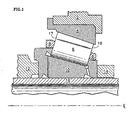
- an embodiment of the invention includes a roller bearing assembly with four main components: the inner ring 10, the rolling element 6, the outer ring 4, and the cage 8.
- the inner ring 10 is attached to a shaft 16 and secured axially by a seal plate 12 on one end and a nut 14 on the other.
- the outer ring 4 attaches to a housing 2 and remains stationary relative to this housing 2.
- the inner ring 10 is attached to a shaft 16 and rotates at several thousand rpm (revolutions per minute).
- the outer ring 4 remains stationary.
- a plurality of rolling elements 6, are spaced tangentially apart from each other by a cage 8, and retained radially between a stationary outer ring 4 and a rotating inner ring 10.
- the rolling elements 6 through friction with the inner ring 10 rotate about their own axis while traveling around the inner ring's 10 race 26 at a relatively slower tangential velocity to that of the inner ring 10.
- lubricating fluid (not shown) is fed into the rib lubricating fluid collector 62 by a forced lubrication system (not shown).
- the rotating inner ring 10 produces centrifugal force thereby forcing lubricating fluid from the rib lubricating fluid collector 62 through rib radial passageways 60 where it passes through the rib chamber 47, collecting in the rib reservoir 46, filling the rib reservoir 46 circumferentially full, and then spilling over the rib top 45 of the rib dam 44.
- the lubricating fluid is then evenly distributed around a continuous 360 degree circumference onto all rolling elements' 6 (a cross section of one rolling element is shown in Fig 1 ) large diameter end 17 via the rib face 58. Centrifugal force continues to exert itself on the lubricating fluid thereby forcing it against and between the rib face 58 and rolling element 6.
- the lubricating oil forms a microscopic elasto-hydrodynamic film between the rib face 58 and the rolling element 6 and transmits the axial thrust while preventing contact between these elements.
- the inner ring 10 is a tapered roller bearing. These tapered rolling elements 6 each have a large diameter end 17 and a small diameter end 18. These ends refer to the relative diameter of the rolling element's 6 two end faces.
- the inner ring accommodates the large diameter end 17 of the rolling element 6 at the rib 40, and more specifically, at the rib face 58.
- a cross section of the cone 20 is shown.
- the rib 40 and the cone 20 are two separate pieces. This eases manufacturing of the rib 40, especially the rib annulus 42.
- the cone 20 has a cone first end 22, a cone second end 24, a cone inner diameter 28, and a cone outer diameter 30.
- the rolling elements 6 travel around the race 26.
- the cone 20 supplies lubricating fluid to the rolling element 6 via the cone lubricating fluid collector 64 and cone radial passageways 66.
- the rib 40 has a rib first end 54, a rib second end 56, a rib inner diameter 50, and a rib outer diameter 52.
- the rib inner diameter (50) is aligned axially with the cone inner diameter (28).
- the rib 40 provides lubricating fluid to the rolling element 6 via the rib lubricating fluid collector 62, rib radial passageways 60, and the rib annulus 42.
- the rib annulus 42 is comprised of rib reservoir 46 and a rib chamber 47.
- the rib reservoir 46 is defined by a rib reservoir back face 49, a rib reservoir front face 41, and the height of the rib dam 44 where the rib dam 44 comes to its maximum radial distance at the rib top 45.
- the rib dam 44 can be defined radially distally by the rib base 43, and a rib top 45.
- Axially the rib dam can be defined by the rib face58 on one end and on the opposite end by the rib reservoir front face 41.
- the rib chamber 47 can be thought of as a wedge, defined on one end by where the rib chamber 47 meets the rib reservoir 46.
- a second end of the rib chamber 47 can be defined by the oil land 48, rib radial passageways 60 and partially by the race of the cone 26.
- a third end can be defined by the partial rolling element 6 large diameter end 17.
- the rib radial passageways 60 are circular holes.
- the rib radial passageways 60 are scalloped or arcuate in shape, and formed only in the rib 40 (as seen in Figures 3A and 3B ).
- the rib radial passageway surface 55 is the area that contacts the cone first end 22 area to form an inner ring 10 when the rib 10 and cone 20 are separable.
- the plurality of rib radial passageways 60 are equally angled apart from one another.
- the total volume of lubricating fluid that the rib radial passageways 60 can deliver is not greater than the volume that the rib chamber 47 can exhaust.
- the rib radial passageways 60 have a total volume less then the volume of the rib annulus.
- a volume of lubricating fluid may be supplied to the rib annulus 42 which is approximately equal to the total volume of the rib radial passageways 60.
Landscapes
- Engineering & Computer Science (AREA)
- General Engineering & Computer Science (AREA)
- Mechanical Engineering (AREA)
- Rolling Contact Bearings (AREA)
Applications Claiming Priority (1)
| Application Number | Priority Date | Filing Date | Title |
|---|---|---|---|
| US12/287,330 US20100086247A1 (en) | 2008-10-08 | 2008-10-08 | Roller bearing |
Publications (1)
| Publication Number | Publication Date |
|---|---|
| EP2175152A1 true EP2175152A1 (de) | 2010-04-14 |
Family
ID=41510640
Family Applications (1)
| Application Number | Title | Priority Date | Filing Date |
|---|---|---|---|
| EP09251891A Withdrawn EP2175152A1 (de) | 2008-10-08 | 2009-07-28 | Kugellager |
Country Status (2)
| Country | Link |
|---|---|
| US (1) | US20100086247A1 (de) |
| EP (1) | EP2175152A1 (de) |
Cited By (1)
| Publication number | Priority date | Publication date | Assignee | Title |
|---|---|---|---|---|
| EP2886894A1 (de) * | 2013-12-23 | 2015-06-24 | SKF Aerospace France | Mechanische Vorrichtung mit einem Lager und einem Schmiersystem, Inbetriebnahmevorrichtung und -verfahren |
Families Citing this family (4)
| Publication number | Priority date | Publication date | Assignee | Title |
|---|---|---|---|---|
| DE102010047927A1 (de) | 2010-10-08 | 2011-04-21 | Schaeffler Technologies Gmbh & Co. Kg | Wälzlagerkäfig mit Stauscheibe |
| US10451113B2 (en) | 2017-05-18 | 2019-10-22 | General Electric Company | Bearing cages for roller bearing assemblies |
| US10260563B2 (en) | 2017-05-18 | 2019-04-16 | General Electric Company | Bearing cages for roller bearing assemblies |
| DE102019110299A1 (de) * | 2019-04-18 | 2020-10-22 | Schaeffler Technologies AG & Co. KG | Kegelrollenlager |
Citations (8)
| Publication number | Priority date | Publication date | Assignee | Title |
|---|---|---|---|---|
| JPS5072044A (de) * | 1973-10-29 | 1975-06-14 | ||
| US4384749A (en) * | 1981-06-26 | 1983-05-24 | The United States Of America As Represented By The Secretary Of The Air Force | Reliability roller bearing |
| JPH0594531U (ja) * | 1992-05-26 | 1993-12-24 | エヌティエヌ株式会社 | 転がり軸受 |
| JPH0968232A (ja) * | 1995-08-30 | 1997-03-11 | Ntn Corp | 軸受密封装置 |
| JP2005308107A (ja) * | 2004-04-22 | 2005-11-04 | Nsk Ltd | 円すいころ軸受 |
| JP2005351301A (ja) * | 2004-06-08 | 2005-12-22 | Nsk Ltd | ころ軸受 |
| JP2007247783A (ja) * | 2006-03-16 | 2007-09-27 | Ntn Corp | ころ軸受の潤滑構造 |
| JP2008025617A (ja) * | 2006-07-18 | 2008-02-07 | Nsk Ltd | 円すいころ軸受 |
Family Cites Families (14)
| Publication number | Priority date | Publication date | Assignee | Title |
|---|---|---|---|---|
| AT279282B (de) * | 1967-11-29 | 1970-02-25 | Man Turbo Gmbh | Wälzlager für hochtourige Wellen |
| US3528711A (en) * | 1968-09-03 | 1970-09-15 | Gen Motors Corp | Bearing lubrication |
| US3497277A (en) * | 1968-09-03 | 1970-02-24 | Gen Motors Corp | Bearing lubrication |
| FR2128034B1 (de) * | 1971-03-01 | 1975-01-17 | Snecma | |
| GB1334454A (en) * | 1971-06-16 | 1973-10-17 | Timken Co | Roller bearings |
| US3885842A (en) * | 1973-09-21 | 1975-05-27 | Koyo Seiko Co | Bearing lubricating device |
| US4541738A (en) * | 1983-08-11 | 1985-09-17 | The Timken Company | Refrigerant cooled tapered roller bearing assembly |
| JPH11141557A (ja) * | 1997-11-05 | 1999-05-25 | Nippon Seiko Kk | 転がり軸受 |
| US6053636A (en) * | 1998-11-10 | 2000-04-25 | United Technologies Corporation | Hydrostatic bearing with compensatory fluid injection |
| US6464401B1 (en) * | 2001-01-26 | 2002-10-15 | United Technologies Corporation | High load capacity bi-directional tapered roller bearing |
| US6511228B2 (en) * | 2001-05-08 | 2003-01-28 | Pratt & Whitney Canada Corp. | Oil annulus to circumferentially equalize oil feed to inner race of a bearing |
| US8753016B2 (en) * | 2002-07-29 | 2014-06-17 | Nsk Ltd. | Rolling bearing, grease supply system, spindle unit, grease supply method, and grease supply program |
| US20060062504A1 (en) * | 2004-09-23 | 2006-03-23 | Wilton Stephen A | Lubricant distribution weir for lubricating moving machine elements |
| JP2007051716A (ja) * | 2005-08-18 | 2007-03-01 | Jtekt Corp | 円錐ころ軸受、及びこれを用いた車両用ピニオン軸支持装置 |
-
2008
- 2008-10-08 US US12/287,330 patent/US20100086247A1/en not_active Abandoned
-
2009
- 2009-07-28 EP EP09251891A patent/EP2175152A1/de not_active Withdrawn
Patent Citations (8)
| Publication number | Priority date | Publication date | Assignee | Title |
|---|---|---|---|---|
| JPS5072044A (de) * | 1973-10-29 | 1975-06-14 | ||
| US4384749A (en) * | 1981-06-26 | 1983-05-24 | The United States Of America As Represented By The Secretary Of The Air Force | Reliability roller bearing |
| JPH0594531U (ja) * | 1992-05-26 | 1993-12-24 | エヌティエヌ株式会社 | 転がり軸受 |
| JPH0968232A (ja) * | 1995-08-30 | 1997-03-11 | Ntn Corp | 軸受密封装置 |
| JP2005308107A (ja) * | 2004-04-22 | 2005-11-04 | Nsk Ltd | 円すいころ軸受 |
| JP2005351301A (ja) * | 2004-06-08 | 2005-12-22 | Nsk Ltd | ころ軸受 |
| JP2007247783A (ja) * | 2006-03-16 | 2007-09-27 | Ntn Corp | ころ軸受の潤滑構造 |
| JP2008025617A (ja) * | 2006-07-18 | 2008-02-07 | Nsk Ltd | 円すいころ軸受 |
Cited By (2)
| Publication number | Priority date | Publication date | Assignee | Title |
|---|---|---|---|---|
| EP2886894A1 (de) * | 2013-12-23 | 2015-06-24 | SKF Aerospace France | Mechanische Vorrichtung mit einem Lager und einem Schmiersystem, Inbetriebnahmevorrichtung und -verfahren |
| US9382945B2 (en) | 2013-12-23 | 2016-07-05 | SKF Aerospace France S.A.S | Mechanical device comprising a bearing and a lubrication system, implementing machine and method |
Also Published As
| Publication number | Publication date |
|---|---|
| US20100086247A1 (en) | 2010-04-08 |
Similar Documents
| Publication | Publication Date | Title |
|---|---|---|
| EP2574805B1 (de) | Lagerölschmierungssystem | |
| US8668432B2 (en) | Bearing arrangement having a double-row roller bearing, turbocharger and method for feeding a lubricant to the rows of rolling bodies of a double-row roller bearing | |
| US8517612B2 (en) | Bearing oiling system | |
| US8529135B2 (en) | Angular contact ball bearing | |
| EP0081281A1 (de) | Kegelrollenlager | |
| US2911267A (en) | Failsafe bearing lubrication | |
| US20100086247A1 (en) | Roller bearing | |
| EP2189673B1 (de) | Wälzkörperlager | |
| EP2133513A3 (de) | Lageranordnung | |
| US20060193545A1 (en) | Rolling element bearing cage with improved pilot surface lubrication | |
| WO2013028284A1 (en) | Bearing cage for a roller bearing assembly | |
| US10047794B2 (en) | Rolling bearing for an exhaust gas turbocharger, and cage for a rolling bearing | |
| EP2886894B1 (de) | Mechanische Vorrichtung mit einem Lager und einem Schmiersystem, Inbetriebnahmevorrichtung und -verfahren | |
| JP2004076766A (ja) | 円すいころ軸受 | |
| JP5910058B2 (ja) | 転がり軸受装置 | |
| US4120541A (en) | Lubricating device | |
| US10619673B2 (en) | Rolling bearing | |
| JP2005351439A (ja) | 円筒ころ軸受のエアオイル潤滑構造 | |
| US10871191B2 (en) | Rolling bearing and bearing structure including same | |
| CN113187882A (zh) | 一种用于锥齿轮轴承的润滑结构 | |
| JP4126529B2 (ja) | 円すいころ軸受 | |
| CN214999306U (zh) | 一种用于主锥齿轮轴承润滑的甩油环及其主锥齿轮轴承 | |
| CN114992233A (zh) | 具有润滑剂保持器的轴承组件 | |
| CN113154017A (zh) | 一种用于主锥齿轮轴承润滑的甩油环及其主锥齿轮轴承 | |
| JP5024114B2 (ja) | ターボチャージャ用軸受装置 |
Legal Events
| Date | Code | Title | Description |
|---|---|---|---|
| PUAI | Public reference made under article 153(3) epc to a published international application that has entered the european phase |
Free format text: ORIGINAL CODE: 0009012 |
|
| AK | Designated contracting states |
Kind code of ref document: A1 Designated state(s): AT BE BG CH CY CZ DE DK EE ES FI FR GB GR HR HU IE IS IT LI LT LU LV MC MK MT NL NO PL PT RO SE SI SK SM TR |
|
| AX | Request for extension of the european patent |
Extension state: AL BA RS |
|
| 17P | Request for examination filed |
Effective date: 20100604 |
|
| 17Q | First examination report despatched |
Effective date: 20100715 |
|
| STAA | Information on the status of an ep patent application or granted ep patent |
Free format text: STATUS: THE APPLICATION IS DEEMED TO BE WITHDRAWN |
|
| 18D | Application deemed to be withdrawn |
Effective date: 20101126 |