EP2175159A2 - Amortisseur de vibrations de torsions - Google Patents
Amortisseur de vibrations de torsions Download PDFInfo
- Publication number
- EP2175159A2 EP2175159A2 EP09171945A EP09171945A EP2175159A2 EP 2175159 A2 EP2175159 A2 EP 2175159A2 EP 09171945 A EP09171945 A EP 09171945A EP 09171945 A EP09171945 A EP 09171945A EP 2175159 A2 EP2175159 A2 EP 2175159A2
- Authority
- EP
- European Patent Office
- Prior art keywords
- torsional vibration
- vibration damper
- damping
- piston
- damper according
- Prior art date
- Legal status (The legal status is an assumption and is not a legal conclusion. Google has not performed a legal analysis and makes no representation as to the accuracy of the status listed.)
- Withdrawn
Links
- 238000013016 damping Methods 0.000 claims abstract description 125
- 239000000872 buffer Substances 0.000 claims description 5
- 239000013013 elastic material Substances 0.000 claims description 5
- 238000007789 sealing Methods 0.000 description 5
- 230000001419 dependent effect Effects 0.000 description 3
- 238000006073 displacement reaction Methods 0.000 description 3
- 239000006096 absorbing agent Substances 0.000 description 2
- 230000005284 excitation Effects 0.000 description 2
- 230000035939 shock Effects 0.000 description 2
- 230000007704 transition Effects 0.000 description 2
- 240000001439 Opuntia Species 0.000 description 1
- 235000004727 Opuntia ficus indica Nutrition 0.000 description 1
- 230000002411 adverse Effects 0.000 description 1
- 230000002238 attenuated effect Effects 0.000 description 1
- 238000010586 diagram Methods 0.000 description 1
- 230000000694 effects Effects 0.000 description 1
- 239000012530 fluid Substances 0.000 description 1
- 238000009434 installation Methods 0.000 description 1
- 230000003993 interaction Effects 0.000 description 1
- 239000007788 liquid Substances 0.000 description 1
- 239000002184 metal Substances 0.000 description 1
- 230000010355 oscillation Effects 0.000 description 1
- 239000011343 solid material Substances 0.000 description 1
- 239000000725 suspension Substances 0.000 description 1
Images


Classifications
-
- F—MECHANICAL ENGINEERING; LIGHTING; HEATING; WEAPONS; BLASTING
- F16—ENGINEERING ELEMENTS AND UNITS; GENERAL MEASURES FOR PRODUCING AND MAINTAINING EFFECTIVE FUNCTIONING OF MACHINES OR INSTALLATIONS; THERMAL INSULATION IN GENERAL
- F16F—SPRINGS; SHOCK-ABSORBERS; MEANS FOR DAMPING VIBRATION
- F16F9/00—Springs, vibration-dampers, shock-absorbers, or similarly-constructed movement-dampers using a fluid or the equivalent as damping medium
- F16F9/10—Springs, vibration-dampers, shock-absorbers, or similarly-constructed movement-dampers using a fluid or the equivalent as damping medium using liquid only; using a fluid of which the nature is immaterial
- F16F9/14—Devices with one or more members, e.g. pistons, vanes, moving to and fro in chambers and using throttling effect
- F16F9/145—Devices with one or more members, e.g. pistons, vanes, moving to and fro in chambers and using throttling effect involving only rotary movement of the effective parts
-
- F—MECHANICAL ENGINEERING; LIGHTING; HEATING; WEAPONS; BLASTING
- F16—ENGINEERING ELEMENTS AND UNITS; GENERAL MEASURES FOR PRODUCING AND MAINTAINING EFFECTIVE FUNCTIONING OF MACHINES OR INSTALLATIONS; THERMAL INSULATION IN GENERAL
- F16F—SPRINGS; SHOCK-ABSORBERS; MEANS FOR DAMPING VIBRATION
- F16F9/00—Springs, vibration-dampers, shock-absorbers, or similarly-constructed movement-dampers using a fluid or the equivalent as damping medium
- F16F9/06—Springs, vibration-dampers, shock-absorbers, or similarly-constructed movement-dampers using a fluid or the equivalent as damping medium using both gas and liquid
-
- F—MECHANICAL ENGINEERING; LIGHTING; HEATING; WEAPONS; BLASTING
- F16—ENGINEERING ELEMENTS AND UNITS; GENERAL MEASURES FOR PRODUCING AND MAINTAINING EFFECTIVE FUNCTIONING OF MACHINES OR INSTALLATIONS; THERMAL INSULATION IN GENERAL
- F16F—SPRINGS; SHOCK-ABSORBERS; MEANS FOR DAMPING VIBRATION
- F16F9/00—Springs, vibration-dampers, shock-absorbers, or similarly-constructed movement-dampers using a fluid or the equivalent as damping medium
- F16F9/10—Springs, vibration-dampers, shock-absorbers, or similarly-constructed movement-dampers using a fluid or the equivalent as damping medium using liquid only; using a fluid of which the nature is immaterial
- F16F9/14—Devices with one or more members, e.g. pistons, vanes, moving to and fro in chambers and using throttling effect
-
- F—MECHANICAL ENGINEERING; LIGHTING; HEATING; WEAPONS; BLASTING
- F16—ENGINEERING ELEMENTS AND UNITS; GENERAL MEASURES FOR PRODUCING AND MAINTAINING EFFECTIVE FUNCTIONING OF MACHINES OR INSTALLATIONS; THERMAL INSULATION IN GENERAL
- F16F—SPRINGS; SHOCK-ABSORBERS; MEANS FOR DAMPING VIBRATION
- F16F9/00—Springs, vibration-dampers, shock-absorbers, or similarly-constructed movement-dampers using a fluid or the equivalent as damping medium
- F16F9/32—Details
- F16F9/48—Arrangements for providing different damping effects at different parts of the stroke
Definitions
- the invention relates to a torsional vibration damper according to the preamble of claim 1.
- a torsional vibration damper with a stator stator having several stator in which a winged rotor is rotatably received about a rotation axis.
- a rotational movement of the rotor about its axis of rotation at least two working chambers filled with a damping medium and opposing their volume are formed, the flows being conductively connected via at least one flow connection to a compensation chamber having at least two damping units.
- the existing in the expansion chamber damping units are arranged stationary in the known embodiment.
- the damping units have damping valves, or throttle points, which are suitable for selectively influencing the damping behavior of the torsional vibration damper.
- a device for vibration damping in the example of a telescopic shock absorber, in which a movable piston with a fixed piston in the form of a series connection of two damping units are provided.
- the damping units each have damping valves or throttling points and thus allow a targeted influencing of the damping behavior of such a telescopic shock absorber.
- the movable piston is also movable against the force of a plurality of spring elements.
- the invention has for its object to provide a torsional vibration damper, which is simple and compact, while having a device that changes the attenuation quantity as a function of the excitation amplitude.
- a torsional vibration damper having a stator having at least one stator vane and a rotor having at least one vane, which together form at least two working chambers filled with a damping medium and opposing each other in a relative movement between stator and rotor, which in turn conduct currents via at least one flow connection are connected to a compensation chamber having at least two damping units, according to the invention has been further developed such that the torsional vibration damper has an amplitude-controlled damping such that a second, movable damping unit is assigned to a first, fixed in the rotor damping unit.
- the value of the damping which can be achieved by the torsional vibration damper according to the invention, can be varied as desired as a function of the excitation amplitude and can therefore be determined in advance.
- This previously unknown in torsional vibration dampers possibility of amplitude-selective damping extends the range of applications of such torsional vibration dampers to a decisive extent.
- an increase in comfort of equipped with the torsional vibration dampers according to the invention by improving the wheel suspension is recorded.
- a first embodiment of the invention relates to the fact that both damping units are part of a cartridge designed as a preassembled structural unit.
- the torsional vibration damper can be made very compact and its installation is easier than is the case with known torsional vibration dampers.
- a torsional vibration damper in which the first, fixedly arranged in the rotor damping unit is associated with a second, movable against the force of at least one elastic spring element damping unit.
- first and the second damping unit can be connected in parallel to each other or in series with each other.
- damping characteristics of a torsional vibration damper can be specifically influenced.
- both damping units are mutually permeable by the damping medium. Through this mutual flow through the flow-conducting connections can be provided directly in the damping units, so that no additional flow channels are required.
- a development of the invention consists in that both damping units are arranged in the compensation space, between a first flow connection to the first working chamber and a second flow connection to the second working chamber.
- the compact design of the torsional vibration damper according to the invention expresses itself, because a plurality of functionally essential components are arranged in a small space. It is also of particular importance that the elements used for damping elements of the torsional vibration damper are provided within the rotor. This means optimum space utilization according to the present invention.
- the second, movable damping unit is designed as a displaceable piston in the compensation chamber with damping valves present therein.
- the design of the damping unit as a displaceable piston has several advantages.
- the possibility can be created to provide damping valves in the piston. This contributes to the solution of the task to be able to perform the torsional vibration damper compact overall.
- the piston also suitable to be displaced within the compensation space against the force of at least one elastic spring element.
- a special embodiment variant is that the second damping unit is a piston acted on both sides by elastic spring elements. This takes into account the fact that the damping unit can be alternately flowed through. Thus, in both directions of movement of the damping unit can specifically influence the properties of the damping of the damping fluid present in the torsional vibration damper.
- elastic spring elements springs of any type or elastomeric body can be used.
- the piston is acted upon on both sides by two elastic spring elements of different spring constants, which in addition to the mutual flowability with the damping medium has the advantage that in a simple manner an amplitude-selective damping can be achieved because the spring element with the higher spring constant only from a Value responds when the spring element with the lower spring constant has reached a predetermined limit.
- a plurality of damping stages can be achieved within the torsional vibration damper by simple structural means, namely by maintaining a defined sequence of the damping units and the provided elastic spring elements.
- a development of the invention also provides that the first damping unit has throttle points which are at least partially covered by valve plates in the respective outflow direction.
- the first, fixed in the torsional vibration damper damping unit is an element that consists of torsional vibration dampers previously known type is already known.
- a very advantageous and alternative embodiment of a torsional vibration damper according to the invention is seen in that the second damping unit is arranged in a piston chamber within the cartridge and consists of a fixedly installed in the piston chamber damper plate with a passage for the damping medium and a displaceably arranged in the piston chamber piston.
- This special solution is particularly suitable for the parallel connection of the damping units and represents a compact variant.
- the piston may consist of elastic material and have stop buffers on both sides.
- the stop buffer are made of an elastic material and the piston itself, for example, made of metal or another solid material.
- the second damping unit is arranged in this embodiment on a profile of the cartridge in the compensation chamber.
- torsional vibration damper Regardless of the design of the damping units torsional vibration damper according to the invention are characterized in that they have a, separated by a displaceable separating piston from the expansion chamber, a temperature compensation ensuring compensating space.
- This compensation space can contain a compensation medium in a manner known per se. Since the torsional vibration damper heated due to the internal friction of the damping medium during its operation and this entails an increase in volume, the use of a separating piston with a compensation space behind it is advantageous.
- a valve carrier is arranged between the connecting channel opening into the equalizing space and the separating piston, which causes a pressure drop by means of throughflow openings present therein when the pressure in the connecting channel is greater than the pressure in the compensation space.
- a torsional vibration damper according to the invention is that the cartridge is at least partially inserted into a sleeve.
- This sleeve can advantageously have in its lateral surface a flow channel system which forms a connection between the compensation chamber and at least one leading to the working chambers flow connections.
- the flow channel system can be performed almost arbitrarily and, for example, cause an attenuation within the flow channel system, which is achieved by the oscillation of the liquid column in the flow channel system.
- Another advantage of the use of the sleeve for receiving the cartridge is that the torsional vibration damper can thus be made more compact and thus the initially asked task can be solved in an improved manner.
- the sleeve with its outer circumferential surface forms a flow channel system together with the corresponding inner surface of the rotor.
- This variant has the advantage that the sleeve is very simple executable, since, for example, a simple pipe section can be used as a sleeve.
- the flow channel system can be achieved, for example, by simple measures, such as suitable dimensional tolerances between the sleeve and the inner surface of the rotor.
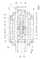
- FIG. 1 shown longitudinal section through a first embodiment of a torsional vibration damper according to the invention shows that this torsional vibration damper consists of a stator 5, which in the present case forms a housing of the torsional vibration damper.
- a rotor 11 is rotatably mounted in the stator 5.
- the interaction between the stator 5 and rotor 11 will be discussed below in connection with the explanations to the FIG. 2 described in more detail.
- the stator 5 has stator blades 1, 3, the rotor 11 being equipped with corresponding blades 7, 9.
- working chambers 13, 15 are formed by the wings 7, 9 of the rotor, which change their volume in opposite directions in a relative movement between the stator 5 and rotor 11.
- the working chambers 13 and 15 are fluidly connected to each other.
- the transition from the working chamber 13 to a central compensation chamber 21 is formed by a flow connection 17, while the transition from the working chamber 15 to the compensation chamber 21 through the flow connection 19 is created.
- the particular feature according to the invention now consists on the one hand in that the compensation chamber 21 is formed inside the rotor 11.
- the compensation chamber 21 also receives two damping units 25 and 27. In this case, the damping unit 25 is within the compensation chamber 21 arranged fixed while the damping unit 27 is carried out within the compensation chamber 21 as a displaceably mounted piston 37.
- the damping unit 27 can be moved within the compensation chamber 21 against the force of a plurality of spring elements 29, 31, 33 and 35 back and forth.
- the design of the springs 29, 31, 33 and 35 defines the damping in connection with the first damping unit 25 connected in series with the second damping unit 27.
- FIG. 1 are formed as a piston 37 damping unit 27 associated on both sides in each case two spring elements.
- an inner spring element 29 is combined with an outer spring 31 whose spring constants differ from one another.
- Analogous spring constants have the inner spring 33 cooperating in the right-hand part of the image with the second damping unit 27 and the outer spring 35.
- the springs 29, 31, 33 and 35 are based on the damper unit 27 opposite side against a respective spring plate 69 and 71 from.
- the mobility of the second damping unit 27 can take place along a guide, which in the FIG. 1 but not shown.
- the first, fixed damping unit 25 has throttle points 41, which can also be traversed on both sides by the damping medium. For at least partial closure of these throttling points 41 serve on both sides of the damping unit 25 valve plates 43 and 45, which open or close depending on the pending pressure of the damping medium.
- the two damping units 25 and 27 are components of a pre-assembled as a cartridge cartridge 23.
- the conclusion of this cartridge forms in the left-hand part of the FIG. 1 a valve carrier 73, which in turn has through-flow openings 83 and is responsible in particular for the temperature-induced pressure compensation within the torsional vibration damper.
- the cartridge 23 is mounted in total on a bolt 75 and fixed with a hex nut 77, which holds the components together.
- the bolt 75 penetrates the valve carrier 73, the first and the second damping unit 25 and 27 and is screwed at the end with a shutter disc 79.
- the second valve unit 27 is further arranged on a tube 97 slidably in the sense of a guide.
- the tube 97 further receives the bolt 75.
- the closure disk 79 allows the cartridge 23 to be fixed in the compensation chamber 21 of the rotor 11.
- the screw ring 81 is accessible from the outside of the rotor 11 and has engagement recesses for suitable tools.
- the temperature-dependent volume changes of the damping medium within the torsional vibration damper, as already stated, on the one hand by means of the valve carrier 73 and a plurality of flow openings contained therein 83 allows.
- a displaceable and sealed against the compensation chamber 21 separating piston 59 is present in the compensation chamber 21, which allows compensation of the temperature-dependent expansion of the damping medium.
- a temperature-induced fluctuation of the damping medium can be compensated by an evasive movement of the separating piston 59, so that an increase in volume of the damping medium does not adversely affect the components of the torsional vibration damper.
- Locked the compensation space 61 is replaced by a lid 85, which is sealed with suitable seals 87 from the environment.
- the stator 5 In order to sufficiently seal the stator 5, which forms a housing of the torsional vibration damper in the present case relative to the environment and to receive the rotor 11 rotatably within the stator 5, the stator 5 is closed with closure covers 89 and 93. These closure covers 89 and 93 have on the outer sides of the stator 5 in each case a sealing ring 91 or 95 for receiving various, suitable for the sealing of the system seals.
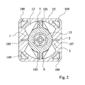
- FIG. 1 shows the illustration in FIG. 2 , It can be seen that the rotor 11 has two diametrically opposite arranged wings 7 and 9. The wings 7 and 9 have wing seals 101 and 103. At the stator 5 are two diametrically opposite arranged stator blades 1 and 3, respectively. These stator blades 1, 3 in turn have wing seals 105 and 107, respectively.
- two working chambers 13 and 15 are defined in the stator 5.
- the stator 5 also has various recesses 109 and / or ribs on its lateral surface.
- FIG. 3 One from the fundamental structure and in the functioning to that in connection with the FIG. 1 explained embodiment variant similar design is in the FIG. 3 shown.
- the essential difference of the execution according to FIG. 3 is that the cartridge 23 is taken up to a predominant extent in a sleeve 65.
- at least the part of the cartridge 23 should be arranged in the sleeve 65, which corresponds to the second damping unit 27.
- a flow channel system 67 can be created in a simple manner, which allows any guidance of the flow channels. Thus, even a damping within this flow channel system 67 is possible.
- the flow channel system 67 is here part of the flow connections 17.
- a special, third embodiment of a torsional vibration damper according to the invention is in connection with the longitudinal section in FIG. 4 explained.
- This in the basic structure to the previously described variants equally executed torsional vibration damper has the peculiarity that the cartridge 23 via a Piston chamber 47 has, in which the second damping unit 27 is arranged.
- the second damping unit 27 consists of a fixed in the piston chamber 47 damper plate 49, which has a constantly open passage 51.
- an axially movable piston 53 is provided on the stopper buffers 55 are made on both sides of an elastic material.
- the first damping unit 25, which has a piston 37 fixedly arranged on a profile 57, is located outside the piston chamber 47 in the compensation chamber 21.
- the piston 37 has damping valves 39.
- the operation of the damping device is the following: If the rotor 11 is rotated about its axis of rotation, the volume of the working chambers 13 and 15, wherein displaced by the displacement of the damping medium, for example via the flow connection 19 damping medium in the expansion chamber 21.
- the damping medium first passes via a channel 111 into the piston chamber 47.
- the inflow of the damping medium via the channel 111 in the piston chamber 47 is made possible by the constantly open passage 51.
- the piston 53 is displaced in the axial direction within the piston chamber 47.
- the path of the piston 53 is limited by a stop on an associated surface of the piston chamber 47.
- the piston 53 bump stop 55 on. As long as the piston moves in the direction of stop, damping medium flows via the opening 113 and is attenuated after reaching a defined differential pressure by the parallel-connected, first damping unit 25, before a transgression into the second working chamber 13 takes place.
Landscapes
- Engineering & Computer Science (AREA)
- General Engineering & Computer Science (AREA)
- Mechanical Engineering (AREA)
- Fluid-Damping Devices (AREA)
Applications Claiming Priority (1)
| Application Number | Priority Date | Filing Date | Title |
|---|---|---|---|
| DE200810042664 DE102008042664B4 (de) | 2008-10-08 | 2008-10-08 | Drehschwingungsdämpfer |
Publications (2)
| Publication Number | Publication Date |
|---|---|
| EP2175159A2 true EP2175159A2 (fr) | 2010-04-14 |
| EP2175159A3 EP2175159A3 (fr) | 2014-07-02 |
Family
ID=41490440
Family Applications (1)
| Application Number | Title | Priority Date | Filing Date |
|---|---|---|---|
| EP09171945.0A Withdrawn EP2175159A3 (fr) | 2008-10-08 | 2009-10-01 | Amortisseur de vibrations de torsions |
Country Status (2)
| Country | Link |
|---|---|
| EP (1) | EP2175159A3 (fr) |
| DE (1) | DE102008042664B4 (fr) |
Cited By (4)
| Publication number | Priority date | Publication date | Assignee | Title |
|---|---|---|---|---|
| CN104160173A (zh) * | 2012-03-05 | 2014-11-19 | 萱场工业株式会社 | 旋转减震器 |
| EP2824357A4 (fr) * | 2012-03-05 | 2015-12-09 | Kayaba Industry Co Ltd | Amortisseur rotatif |
| CN107151978A (zh) * | 2017-06-08 | 2017-09-12 | 重庆工商职业学院 | 桥梁减振支座 |
| CN116464730A (zh) * | 2023-04-13 | 2023-07-21 | 四川凌峰航空液压机械有限公司 | 封闭式旋摆叶片节流孔式热平衡液压阻尼器 |
Citations (2)
| Publication number | Priority date | Publication date | Assignee | Title |
|---|---|---|---|---|
| DE10041199C1 (de) | 2000-08-23 | 2001-11-29 | Mannesmann Sachs Ag | Schwingungsdämpfer |
| DE102004026043B3 (de) | 2004-05-27 | 2005-12-15 | Zf Friedrichshafen Ag | Drehschwingungsdämpfer |
Family Cites Families (5)
| Publication number | Priority date | Publication date | Assignee | Title |
|---|---|---|---|---|
| US2096468A (en) * | 1936-09-25 | 1937-10-19 | Houde Eng Corp | Valving assembly for hydraulic shock absorbers |
| US2286291A (en) * | 1941-05-15 | 1942-06-16 | Houdaille Hershey Corp | Hydraulic shock absorber valve structure |
| DE19700422C2 (de) * | 1997-01-09 | 2003-12-24 | Zf Sachs Ag | Drehschwingungsdämpfer |
| DE102005040284A1 (de) * | 2005-08-24 | 2007-03-08 | Zf Friedrichshafen Ag | Schwingungsdämpfer |
| DE102005060309B3 (de) * | 2005-12-16 | 2007-05-31 | Zf Friedrichshafen Ag | Schwingungsdämpfer mit amplitudenselektiver Dämpfkraft |
-
2008
- 2008-10-08 DE DE200810042664 patent/DE102008042664B4/de not_active Expired - Fee Related
-
2009
- 2009-10-01 EP EP09171945.0A patent/EP2175159A3/fr not_active Withdrawn
Patent Citations (2)
| Publication number | Priority date | Publication date | Assignee | Title |
|---|---|---|---|---|
| DE10041199C1 (de) | 2000-08-23 | 2001-11-29 | Mannesmann Sachs Ag | Schwingungsdämpfer |
| DE102004026043B3 (de) | 2004-05-27 | 2005-12-15 | Zf Friedrichshafen Ag | Drehschwingungsdämpfer |
Cited By (8)
| Publication number | Priority date | Publication date | Assignee | Title |
|---|---|---|---|---|
| CN104160173A (zh) * | 2012-03-05 | 2014-11-19 | 萱场工业株式会社 | 旋转减震器 |
| EP2824358A4 (fr) * | 2012-03-05 | 2015-12-02 | Kayaba Industry Co Ltd | Amortisseur rotatif |
| EP2824357A4 (fr) * | 2012-03-05 | 2015-12-09 | Kayaba Industry Co Ltd | Amortisseur rotatif |
| US9404550B2 (en) | 2012-03-05 | 2016-08-02 | Kyb Corporation | Rotary damper |
| US9702425B2 (en) | 2012-03-05 | 2017-07-11 | Kyb Corporation | Rotary damper |
| CN107151978A (zh) * | 2017-06-08 | 2017-09-12 | 重庆工商职业学院 | 桥梁减振支座 |
| CN107151978B (zh) * | 2017-06-08 | 2023-04-28 | 重庆工商职业学院 | 桥梁减振支座 |
| CN116464730A (zh) * | 2023-04-13 | 2023-07-21 | 四川凌峰航空液压机械有限公司 | 封闭式旋摆叶片节流孔式热平衡液压阻尼器 |
Also Published As
| Publication number | Publication date |
|---|---|
| DE102008042664B4 (de) | 2015-03-19 |
| EP2175159A3 (fr) | 2014-07-02 |
| DE102008042664A1 (de) | 2010-04-15 |
Similar Documents
| Publication | Publication Date | Title |
|---|---|---|
| DE102005055801B3 (de) | Schwingungsdämpfer mit amplitudenselektiver Dämpfungseinrichtung | |
| EP2255103B1 (fr) | Amortisseur de vibrations comportant une soupape attachée au tube d'amortisseur | |
| DE69005747T2 (de) | Ventil für hydraulische Flüssigkeit und ein mit einem solchen Ventil ausgerüsteter Dämpfer. | |
| DE19811581B4 (de) | Schwingungsdämpfer | |
| EP2796674B1 (fr) | Soupape central pour un moteur pivotant à l'ajustage | |
| DE102007026378A1 (de) | Schwingungsdämpfer | |
| AT524746B1 (de) | Hydraulischer Rotationsdämpfer | |
| DE112015003745T5 (de) | Stoßdämpfer mit frequenzabhängigem passiven Ventil | |
| DE102008042664B4 (de) | Drehschwingungsdämpfer | |
| WO2017162425A1 (fr) | Clapet anti-retour pour une bielle pour un moteur à combustion interne avec compression variable ainsi que bielle avec clapet anti-retour | |
| DE102005008162B3 (de) | Dämpfventil | |
| EP3303101B1 (fr) | Unité de cylindre | |
| DE3246866A1 (de) | Hydraulischer daempfer | |
| DE102018116966A1 (de) | Rückschlagventil für einen Pleuel einer Brennkraftmaschine mit variabler Verdichtung sowie Pleuel mit einem Rückschlagventil | |
| DE102021204441A1 (de) | Ventilanordnung für eine Dämpfervorrichtung sowie Dämpfervorrichtung mit der Ventilanordnung | |
| DE19842155A1 (de) | Ventileinrichtung | |
| DE102007003063A1 (de) | Verstellbares Luftfeder-Dämpfer-Element | |
| DE102014203879B4 (de) | Kolben-Zylinder-Einheit und Türscharnier | |
| DE102013113357A1 (de) | Ventil | |
| DE102018004082A1 (de) | Schaltventil zum Einstellen eines Fluidstroms | |
| DE102010041606B4 (de) | Dämpfventilanordnung für einen Schwingungsdämpfer | |
| DE112022004304T5 (de) | Stossdämpfer | |
| DE102021214563A1 (de) | Externes Dämpfventil für einen Schwingungsdämpfer sowie Schwingungsdämpfer mit dem Dämpfventil | |
| DE102010031144A1 (de) | Schwingungsdämpfer mit amplitudenabhängiger Dämpfkraft | |
| DE102005004982A1 (de) | Gasfeder |
Legal Events
| Date | Code | Title | Description |
|---|---|---|---|
| PUAI | Public reference made under article 153(3) epc to a published international application that has entered the european phase |
Free format text: ORIGINAL CODE: 0009012 |
|
| AK | Designated contracting states |
Kind code of ref document: A2 Designated state(s): AT BE BG CH CY CZ DE DK EE ES FI FR GB GR HR HU IE IS IT LI LT LU LV MC MK MT NL NO PL PT RO SE SI SK SM TR |
|
| AX | Request for extension of the european patent |
Extension state: AL BA RS |
|
| PUAL | Search report despatched |
Free format text: ORIGINAL CODE: 0009013 |
|
| AK | Designated contracting states |
Kind code of ref document: A3 Designated state(s): AT BE BG CH CY CZ DE DK EE ES FI FR GB GR HR HU IE IS IT LI LT LU LV MC MK MT NL NO PL PT RO SE SI SK SM TR |
|
| AX | Request for extension of the european patent |
Extension state: AL BA RS |
|
| RIC1 | Information provided on ipc code assigned before grant |
Ipc: F16F 9/06 20060101AFI20140523BHEP Ipc: F16F 9/14 20060101ALI20140523BHEP Ipc: F16F 9/48 20060101ALI20140523BHEP |
|
| STAA | Information on the status of an ep patent application or granted ep patent |
Free format text: STATUS: THE APPLICATION IS DEEMED TO BE WITHDRAWN |
|
| 18D | Application deemed to be withdrawn |
Effective date: 20150106 |