EP2175164B1 - Mécanisme de réglage pour un élément réglable d'un meuble - Google Patents
Mécanisme de réglage pour un élément réglable d'un meuble Download PDFInfo
- Publication number
- EP2175164B1 EP2175164B1 EP20080166132 EP08166132A EP2175164B1 EP 2175164 B1 EP2175164 B1 EP 2175164B1 EP 20080166132 EP20080166132 EP 20080166132 EP 08166132 A EP08166132 A EP 08166132A EP 2175164 B1 EP2175164 B1 EP 2175164B1
- Authority
- EP
- European Patent Office
- Prior art keywords
- gear
- shaft
- housing
- drive
- displacement sensor
- Prior art date
- Legal status (The legal status is an assumption and is not a legal conclusion. Google has not performed a legal analysis and makes no representation as to the accuracy of the status listed.)
- Not-in-force
Links
- 210000000078 claw Anatomy 0.000 claims description 22
- 238000006073 displacement reaction Methods 0.000 claims description 21
- 238000004891 communication Methods 0.000 claims description 9
- 230000005540 biological transmission Effects 0.000 claims description 8
- 230000000474 nursing effect Effects 0.000 claims description 6
- 230000009467 reduction Effects 0.000 claims description 5
- 230000001939 inductive effect Effects 0.000 claims 1
- 230000003287 optical effect Effects 0.000 claims 1
- 230000008901 benefit Effects 0.000 description 3
- 238000010276 construction Methods 0.000 description 3
- 230000008878 coupling Effects 0.000 description 2
- 238000010168 coupling process Methods 0.000 description 2
- 238000005859 coupling reaction Methods 0.000 description 2
- 230000002093 peripheral effect Effects 0.000 description 2
- 230000009471 action Effects 0.000 description 1
- 230000015572 biosynthetic process Effects 0.000 description 1
- 230000000295 complement effect Effects 0.000 description 1
- 230000008602 contraction Effects 0.000 description 1
- 230000000694 effects Effects 0.000 description 1
- 239000007788 liquid Substances 0.000 description 1
- 238000012423 maintenance Methods 0.000 description 1
- 239000007769 metal material Substances 0.000 description 1
- 238000000034 method Methods 0.000 description 1
- BASFCYQUMIYNBI-UHFFFAOYSA-N platinum Chemical compound [Pt] BASFCYQUMIYNBI-UHFFFAOYSA-N 0.000 description 1
- 230000008569 process Effects 0.000 description 1
Images


Classifications
-
- A—HUMAN NECESSITIES
- A61—MEDICAL OR VETERINARY SCIENCE; HYGIENE
- A61G—TRANSPORT, PERSONAL CONVEYANCES, OR ACCOMMODATION SPECIALLY ADAPTED FOR PATIENTS OR DISABLED PERSONS; OPERATING TABLES OR CHAIRS; CHAIRS FOR DENTISTRY; FUNERAL DEVICES
- A61G7/00—Beds specially adapted for nursing; Devices for lifting patients or disabled persons
- A61G7/002—Beds specially adapted for nursing; Devices for lifting patients or disabled persons having adjustable mattress frame
- A61G7/018—Control or drive mechanisms
-
- F—MECHANICAL ENGINEERING; LIGHTING; HEATING; WEAPONS; BLASTING
- F16—ENGINEERING ELEMENTS AND UNITS; GENERAL MEASURES FOR PRODUCING AND MAINTAINING EFFECTIVE FUNCTIONING OF MACHINES OR INSTALLATIONS; THERMAL INSULATION IN GENERAL
- F16H—GEARING
- F16H1/00—Toothed gearings for conveying rotary motion
- F16H1/02—Toothed gearings for conveying rotary motion without gears having orbital motion
- F16H1/04—Toothed gearings for conveying rotary motion without gears having orbital motion involving only two intermeshing members
- F16H1/12—Toothed gearings for conveying rotary motion without gears having orbital motion involving only two intermeshing members with non-parallel axes
- F16H1/16—Toothed gearings for conveying rotary motion without gears having orbital motion involving only two intermeshing members with non-parallel axes comprising worm and worm-wheel
-
- F—MECHANICAL ENGINEERING; LIGHTING; HEATING; WEAPONS; BLASTING
- F16—ENGINEERING ELEMENTS AND UNITS; GENERAL MEASURES FOR PRODUCING AND MAINTAINING EFFECTIVE FUNCTIONING OF MACHINES OR INSTALLATIONS; THERMAL INSULATION IN GENERAL
- F16H—GEARING
- F16H25/00—Gearings comprising primarily only cams, cam-followers and screw-and-nut mechanisms
- F16H25/18—Gearings comprising primarily only cams, cam-followers and screw-and-nut mechanisms for conveying or interconverting oscillating or reciprocating motions
- F16H25/20—Screw mechanisms
- F16H25/2015—Means specially adapted for stopping actuators in the end position; Position sensing means
-
- F—MECHANICAL ENGINEERING; LIGHTING; HEATING; WEAPONS; BLASTING
- F16—ENGINEERING ELEMENTS AND UNITS; GENERAL MEASURES FOR PRODUCING AND MAINTAINING EFFECTIVE FUNCTIONING OF MACHINES OR INSTALLATIONS; THERMAL INSULATION IN GENERAL
- F16H—GEARING
- F16H25/00—Gearings comprising primarily only cams, cam-followers and screw-and-nut mechanisms
- F16H25/18—Gearings comprising primarily only cams, cam-followers and screw-and-nut mechanisms for conveying or interconverting oscillating or reciprocating motions
- F16H25/20—Screw mechanisms
- F16H25/24—Elements essential to such mechanisms, e.g. screws, nuts
- F16H25/2454—Brakes; Rotational locks
Definitions
- the invention relates to an adjusting drive for an adjustable part of a piece of furniture, in particular for the height and / or lying surface adjustment of a bed such as a hospital or nursing bed.
- Electrically adjustable furniture such as height-adjustable tables, chairs, sofas and chairs with Weg lake- and / or backrest adjustment or beds, especially hospital or nursing beds with height and / or reclining require as compact adjustment drives that are low maintenance, easy to install and reliable or work should. Examples of such adjustment can be found in DE 296 06 367 U1 . DE 20 2007 006 469 U1 . DE 20 2007 005 308 U1 . EP 1 400 726 A1 . EP 0 662 573 B1 and DE 103 29 097 A1 ,
- adjusting drives have a housing and a transmission arranged in the housing.
- this transmission comprises a rotatable, motor-driven drive element and an output element which can be brought into operative connection with the adjustable part of a piece of furniture.
- the drive element is driven as a rule by an electric motor, with the drive shaft, the drive element is rotatably connected. From the DE-A-101 34 937 An adjusting drive according to the preamble of claim 1 is known.
- Each unit connected to the bus requires a bus communication interface with corresponding electronics, which is complicated and in particular also complicates the bus protocol and the bus communication.
- the object of the invention is therefore to provide an adjustment for an adjustable part of a piece of furniture, in which the feedback of the position of the adjustable with the adjusting part is realized in a simple manner.
- the invention proposes an adjusting drive for an adjustable part of a piece of furniture, in particular for height and / or lying surface adjustment of a bed such as a hospital or nursing bed, wherein the adjusting drive is provided with the features of claim 1.
- the drive element between two substantially opposite gears is arranged.
- the first of these two gears is coupled to the output element (directly or indirectly via a transmission, for example).
- the output element directly or indirectly via a transmission, for example.
- the second gear thus serves to accommodate the above-described, occurring under drive load and acting on the drive element torques.
- This second gear is used to operate a displacement transducer coupled to the second gear (directly or indirectly).
- the displacement sensor serves to determine the (rotational) position of the output element.
- the second gear can be used twice, which leads to a total compact construction of the adjustment. If such an adjustment drive is connected to a bus, then both the adjustment drive can be controlled via a single bus interface, as well as the current position of the output element are reported by the adjustment. From this information can then be closed in a parent unit on the adjustment of the adjustable part of the furniture.
- the displacement sensor is expediently a potentiometer and in particular a rotary potentiometer. Such Weggeber are robust and work reliably.
- resistively operating encoders other electrically, capacitively, inductively, optically or magnetically operating displacement sensors or sensors come into question.
- the displacement sensor can be either a relative or an absolute position encoder.
- the displacement sensor can also be designed as a decoder.
- the motor-driven drive element is located between two gears.
- the drive element is expediently designed as a worm.
- the drive element itself may be designed as a gear.
- the two gears for example, a helical toothing, which are in engagement with the worm.
- the two gears each have a first toothing, which meshes with the output element and a second toothing, over which they mesh directly with each other. This leads to an increased resistance of the coupling of worm and first gear, if the drive accidentally "blocks" by the resistance of the worm is increased by the gear wheels increased.
- a bus communication unit and the displacement sensor are arranged on a common board, which in turn is housed protected in the housing.
- the output element of the transmission of the adjusting drive is expediently a gear (for example for driving a toothed belt) or a spindle which meshes with a spindle nut and a represents linearly movable output element. It is also conceivable to selectively connect the output element with a gear or a spindle rotatably. This increases the range of application of the adjustment.
- the known adjustment drives mentioned at the beginning have load torque locks which prevent the output element from being moved by externally acting moments when the motor is switched off.
- claw brakes with coil springs, which are radially outwardly biased arranged in a brake drum.
- Such a brake which is automatically activated when acting on the driven element in the directions of movement of the output element acting torques, can be a simple way and integrate manner in the adjusting drive according to the invention.
- the adjusting expediently has a 2-part shaft between the first gear and the driven element. This two-part shaft is provided with a gear shaft coupled to the gear and with an output member shaft coupled to the output member.
- Both shaft parts engage in each other via axially projecting jaws, so that upon rotation of the first gear or the gear shaft, the output element shaft is entrained.
- a brake drum with arranged in this Bolt brake spring provided, both of which are arranged in the region of the intermeshing claws around the two-part shaft around.
- the fferenbremsfeder has at its two ends radially inwardly projecting driver arms which protrude between two circumferentially consecutive claws of the two shaft parts.
- the housing is formed in three parts and a first housing part, on which the motor is fixed by extending its drive shaft in the first housing part inside, connectable to the first housing part, on two opposite sides open second housing part and has a cover closing the second housing part.
- the cover, the first and the second housing part are interconnected by means of connecting elements which extend between the cover and the first housing part and through the second housing part.
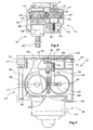
- the adjusting drive 10 has a three-part housing 12 in this embodiment, with which the housing 14 of an electric motor 16 is fixedly connected, the electric motor 16 has a drive shaft 18 which extends into the housing 12 inside.
- a gear 20 is arranged, that a trained as a screw 24, rotatably connected to the motor shaft 18 drive element and a standing in engagement with this first gear 28 has.
- the first gear 28 is coupled via a shaft 30 to an output element 32.
- the output element 32 is in the embodiment according to Fig. 2 around a gear 34, for example for driving a toothed belt, while in Fig. 3 as output element 32, a spindle 36 is shown.
- Both output elements can be advantageously connected to the shaft 30 rotatably. This is served in the Fig. 2 and 3 indicated coupling, which is formed for example as a polygonal pin with complementary square recess. But it is also possible that the gear 34 and the spindle 36 is permanently and thus not detachably connected to the shaft 30.
- the housing 12 has a second gear 40, which is also driven in rotation by the drive element 26 (screw 24) (see the first teeth 22). Both Gears each have a toothing 41, over which they mesh directly with each other.
- the second gear 40 is part of a (reduction) gear stage 42 for actuating a displacement sensor 44 with encoder element 45th
- the second gear 40 is, relative to the position of the drive member 26, the first gear 28 opposite. In other words, therefore, the drive element 26 are located directly between the two gears 28 and 40.
- the second gear 40 supports the drive element 26, if on this more to the drive shaft 18 and the first gear 28 directed away torques or torque components act, as in particular then the case is when the adjustment operates under load. In that regard, so the second gear 40 supports the drive shaft 18 and the drive member 26 (screw) from.
- the second gear 40 but also serves the operation of the encoder 44.
- the second gear 40 is part of the gear 42 and is arranged on a common shaft with a worm 46, which in turn drives a gear 48, which on a common shaft is arranged with a smaller diameter gear 50, which in turn drives another gear 52, the shaft 54 finally actuates the encoder 45.
- the displacement sensor 44 is designed as a rotary potentiometer 56 in this embodiment.
- the rotary potentiometer 56 is arranged on a circuit board 58, which has inter alia a bus communication unit 60 and further electrical or electronic components.
- the circuit board 58 is also electrically connected to the motor 16 via a further plug 64.
- the bus communication unit By the bus communication unit, it is possible to control the adjustment 10 via a bus line. At this bus line can then several Adjustment 10 be connected. In this way, for example, all installed in a furniture adjusting drives can be controlled via a single bus communication line. This reduces the wiring effort and thereby improves the quality by reducing the risk of failure by reducing the number of connections in the wiring harness. Furthermore, the use of bus communication units and the connection of the adjustment drives to a bus allows a reduction in the number of connectors, variety of connectors and connector sizes, since the installed adjustment drives are connected consistently via standard plug connections. Finally, the adjustment itself is standardized or it can be used on standardized adjusting drives. The diagnostic capability of all adjusting drives can also be implemented in a simple manner, in that all the adjusting drives and other components connected to the bus can be tested via a diagnostic tester. This simplifies the search for errors, which in turn speeds up the process of fixing the errors.
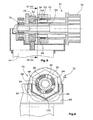
- This also has the three-part construction of the housing 12.
- This has a first housing part 66 to which the housing 14 of the motor 16 is attached.
- a second housing part 68 connects.
- the gears 28, 40 and the first gear 28 to the output element 32 connecting shaft 30 are mounted.
- Parts of the gear stage 42 for the rotary potentiometer 56 are also mounted between the two housing parts 66, 68.
- a cover 70 On the side opposite the first housing part 66 of the second housing part 68 is a cover 70 which covers the held by upstanding pins 72 of the second housing part 68 board 58.
- the three housing components are connected by continuous screws 74 with each other firmly and liquid or splashproof.
- the housing 12 of the drive unit 10 also has a brake 76.
- This brake 76 serves as a load torque lock and prevents the driven element 32 can rotate when the engine 16, if on the output element 32 torques act, for example, by external loads may occur.
- the brake 76 is actuated via the shaft 30.
- the shaft 30 for transmitting the rotational movement of the first gear 28 to the output member 32 is formed in two parts and has a housing 12 at 78 rotatably mounted output member shaft 80 and a gear shaft 82, wherein the first gear 28 rotatably mounted on the output member shaft 80 in this embodiment is stored.
- the output member shaft 80 and the gear shaft 82 are each provided with two opposing, axially projecting claws 84, 86 which engage with each other, whereby upon rotation of the first gear 28, the output member shaft 80 also rotates.
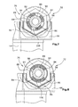
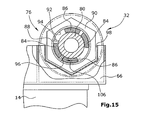
- the engagement of the claws 84 and 86 is in the Fig. 6 to 15 shown.
- the screw brake spring 88 has at its ends in each case a radially inwardly directed driving arm 94, 96.
- the distance between these two driver arms 94, 96 in the circumferential direction of the screw brake spring 88 when viewed in the axial direction Is selected such that one of the two jaws 84 of the gear shaft 82, so one of the two drive-side jaws 84 extends axially between these drive arms 94, 96 therethrough.
- the two driving arms 94, 96 project on both sides of said drive-side jaw 84 in the spaces between this claw 84 and the respective adjacent output-side jaws 86, as for example in Fig. 6 is shown.
- the brake drum 90 is rotatably received in a receptacle 98 of the first housing part 66.
- the brake drum 90 for example, a Hexagon outer contour on.
- the brake drum 90 is expediently made of a metallic material, as is the case with the helical brake spring 88.
- Fig. 6 shows the initial situation, from which now the drive-side claws 84 rotate in the direction of arrow 100.
- the drive-side claw 84 arranged between the two driver arms 94 and 96 comes into contact with the driver arm 96 of the screw brake spring 88 (see FIG Fig. 7 ) which, upon further movement of the claw 84, results in a constriction of the helical brake spring 88, so that it also rotates and as a result the drive-side claws 84 come into contact with the driven-side claws 86, so that the output element 32 is rotated.
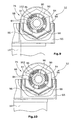
- the situation with rotation of the first gear 28 in the opposite direction is in the Fig. 9 to 11 shown.
- Fig. 12 and 13 show the case that the output member 32 is rotated in the direction of the arrow 104. After a short time, this rotation already leads to one of the two output-side claws 86 coming into contact with one of the two driver arms 94, 96. This situation is in Fig. 13 shown in the one of the two output-side jaws 86 in contact with the driving arm 96 of the screw brake spring 88 passes. Upon further rotation of the claw 86 presses them over the Mitêtarm 96, the fferenbremsfeder 88 increasingly against the inner peripheral side 92 of the Brernstrommel 90, which effectively prevents rotation of the fferenbremsfeder 88 within the brake drum 90. Thus, the output element 32 is braked.
Landscapes
- Health & Medical Sciences (AREA)
- Nursing (AREA)
- Life Sciences & Earth Sciences (AREA)
- Animal Behavior & Ethology (AREA)
- General Health & Medical Sciences (AREA)
- Public Health (AREA)
- Veterinary Medicine (AREA)
- Transmission Devices (AREA)
- Gear Transmission (AREA)
Claims (10)
- Mécanisme de réglage pour un élément réglable d'un meuble, notamment pour le réglage en hauteur ou de la surface de repos d'un lit, pour exemple d'un lit d'hôpital ou un lit de soin, comprenant- un boitier (12),- un engrenage (20) situé dans ledit boitier (12), ledit engrenage comprenant un élément d'entrée (26) rotatif et un élément de sortie (32) apte à être lié de manière fonctionnelle avec un élément réglable d'un meuble,- un moteur (16) avec un arbre d'entrée (18) pour l'entrainement à rotation dudit élément d'entrée (26), et- un capteur de déplacement (44) pour déterminer la position rotatoire dudit élément de sortie (32),- ledit élément d'entrée (26) étant situé entre deux roues dentées (28, 40) sensiblement opposées avec lesquelles ledit élément d'entrée (26) est en contact mécanique, et- la première roue dentée (28) étant couplée avec ledit élément de sortie (32) et la deuxième roue dentée (40) étant couplées avec ledit capteur de déplacement (44),
caractérisé en ce que- lesdites roues dentées (28, 40) respectives comprennent une première denture (22) en prise avec ledit élément d'entrée (26), et une deuxième denture (41) par laquelle les deux roues dentées (28, 40) sont en prise directe l'une avec l'autre. - Mécanisme de réglage selon la revendication 1, caractérisé en ce que ledit capteur de déplacement (44) comprend un élément capteur (45) mobil, et que ladite deuxième roue dentée (40) fait partie d'un train d'un réducteur de vitesse (42) servant à déplacer ledit élément capteur (45) dudit capteur de déplacement (44).
- Mécanisme de réglage selon les revendications 1 ou 2, caractérisé en ce que ledit capteur de déplacement (44) est un capteur de déplacement relatif ou absolu et fonctionne en particulier électriquement, capacitivement, inductivement, résistivement, optiquement ou magnétiquement.
- Mécanisme de réglage selon les revendications 1 ou 2, caractérisé en ce que ledit capteur de déplacement (44) est un potentiomètre (56), notamment un potentiomètre rotatif.
- Mécanisme de réglage selon l'une quelconque des revendications 1 à 4, caractérisé en ce que ledit élément d'entrée (26) situé entre les deux roues dentées (28, 40) est en forme d'une vis sans fin (24).
- Mécanisme de réglage selon l'une quelconque des revendications 1 à 5, caractérisé en ce qu'une unité de communication par bus (60) est prévue dans ou sur ledit boitier (12) pour commander ledit moteur (16) par un système de bus.
- Mécanisme de réglage selon l'une quelconque des revendications 1 à 6, caractérisé en ce qu'une platine (58) avec composants électriques/électroniques est prévu dans ledit boitier (12), ledit capteur de déplacement (44) étant situé sur ladite platine (58).
- Mécanisme de réglage selon l'une quelconque des revendications 1 à 7, caractérisé en ce que ledit boitier (12) est formé en trois parties et comprend une première partie de boitier (66), sur l'extérieur de laquelle est monté ledit moteur (16) dont l'arbre d'entrée (18) s'étend dans ladite première partie de boitier (66), une deuxième partie de boitier (68) connectable avec ladite première partie de boitier (66) et ouverte sur deux côtés opposants, et un couvercle (70) fermant ladite deuxième partie de boitier (68), ledit couvercle, ladite première et ladite deuxième partie de boitier (66, 68) étant interconnectés par des éléments de liaison (74) s'étendant entre ledit couvercle (70) et ladite première partie de boitier (66) et à travers ladite deuxième partie de boitier (68).
- Mécanisme de réglage selon l'une quelconque des revendications 1 à 8, caractérisé en ce qu'entre ladite première roue dentée (28) et ledit élément de sortie (32) un arbre (30) en deux parties est situé, comprenant un arbre de roue dentée (82) couplé avec ladite roue dentée (28) et un arbre d'élément de sortie (80) couplé avec ledit élément de sortie (32), que les deux parties d'arbre (80, 82) comprennent des pattes (84, 86) saillant axialement et étant en prise l'une avec l'autre pour l'entrainement en rotation dudit arbre d'élément de sortie (80) par ledit arbre de roue dentée (82), et qu'un tambour de frein (90) est prévu autour des pattes (84, 86), comprenant un ressort hélicoïdal de frein (88) positionné dans ledit tambour et restant sur l'intérieur dudit tambour de frein (90), les deux extrémités dudit ressort comprenant des bras d'entrainement (94, 96) s'étendant radialement vers l'intérieur, lesdits bras respectifs étant situés entre lesdites pattes (84, 86) dudit arbre de roue dentée (82) et dudit arbre d'élément de sortie (80).
- Mécanisme de réglage selon l'une quelconque des revendications 1 à 9, caractérisé en ce que ledit élément de sortie (32) comprend une roue dentée (34) ou une broche (36) ou un logement (38) pour recevoir une roue dentée (34) ou une broche (36) d'une manière liée en rotation.
Priority Applications (2)
| Application Number | Priority Date | Filing Date | Title |
|---|---|---|---|
| EP20080166132 EP2175164B1 (fr) | 2008-10-08 | 2008-10-08 | Mécanisme de réglage pour un élément réglable d'un meuble |
| ES08166132T ES2371791T3 (es) | 2008-10-08 | 2008-10-08 | Mecanismo de ajuste para una pieza ajustable de un mueble. |
Applications Claiming Priority (1)
| Application Number | Priority Date | Filing Date | Title |
|---|---|---|---|
| EP20080166132 EP2175164B1 (fr) | 2008-10-08 | 2008-10-08 | Mécanisme de réglage pour un élément réglable d'un meuble |
Publications (2)
| Publication Number | Publication Date |
|---|---|
| EP2175164A1 EP2175164A1 (fr) | 2010-04-14 |
| EP2175164B1 true EP2175164B1 (fr) | 2011-08-31 |
Family
ID=40447369
Family Applications (1)
| Application Number | Title | Priority Date | Filing Date |
|---|---|---|---|
| EP20080166132 Not-in-force EP2175164B1 (fr) | 2008-10-08 | 2008-10-08 | Mécanisme de réglage pour un élément réglable d'un meuble |
Country Status (2)
| Country | Link |
|---|---|
| EP (1) | EP2175164B1 (fr) |
| ES (1) | ES2371791T3 (fr) |
Family Cites Families (7)
| Publication number | Priority date | Publication date | Assignee | Title |
|---|---|---|---|---|
| DK4094A (da) | 1994-01-10 | 1995-07-11 | Linak As | Lineær aktuator |
| DE29606367U1 (de) | 1996-04-03 | 1996-08-01 | OKIN Gesellschaft für Antriebstechnik mbH, 51645 Gummersbach | Linearantrieb für Verstelleinrichtungen an Sitz- oder Schlafmöbeln |
| DE10134937A1 (de) | 2001-07-18 | 2003-02-06 | Bosch Gmbh Robert | Getriebe-Antriebseinheit mit Drehzahlerfassung |
| ATE292259T1 (de) | 2002-09-22 | 2005-04-15 | Linak As | Linearantrieb |
| DE10329097A1 (de) | 2003-06-27 | 2005-01-20 | Hiwin Mikrosystem Corp. | Lineare Stellvorrichtung |
| DE202007005308U1 (de) | 2007-04-11 | 2007-06-28 | B. Ketterer Söhne GmbH & Co. KG | Höhenverstelleinrichtung für ein Möbelstück |
| DE202007006469U1 (de) | 2007-05-03 | 2007-08-16 | B. Ketterer Söhne GmbH & Co. KG | Verstellantrieb, insbesondere zur Höhenverstellung eines Möbelstücks |
-
2008
- 2008-10-08 EP EP20080166132 patent/EP2175164B1/fr not_active Not-in-force
- 2008-10-08 ES ES08166132T patent/ES2371791T3/es active Active
Also Published As
| Publication number | Publication date |
|---|---|
| ES2371791T3 (es) | 2012-01-10 |
| EP2175164A1 (fr) | 2010-04-14 |
Similar Documents
| Publication | Publication Date | Title |
|---|---|---|
| EP2246668B1 (fr) | Actionneur électrique | |
| EP2305068B1 (fr) | Poussoir pour un élément de meuble mobile | |
| DE102018221992B4 (de) | Lenkvorrichtung für fahrzeuge | |
| EP0807031B1 (fr) | Mecanisme manuel d'entrainement bidirectionnel servant a generer un mouvement de rotation | |
| DE4403574C1 (de) | Antriebsvorrichtung für ein zwischen Endstellungen verstellbares Teil eines Fahrzeuges | |
| DE20005065U1 (de) | Doppelschneckenstirnradantrieb | |
| EP2504197A1 (fr) | Dispositif de réglage | |
| AT505562B1 (de) | Möbelantrieb | |
| EP0510337B1 (fr) | Dispositif de réglage des éléments en rotation dans une rotative | |
| DE202007015811U1 (de) | Möbelantrieb | |
| EP2655773B1 (fr) | Dispositif de pivotement | |
| DE10254127B4 (de) | Elektromotorischer Möbelantrieb zum Verstellen von Teilen eines Möbels relativ zueinander | |
| DE202008011200U1 (de) | Antriebsvorrichtung für Ein-/Ausstiegsvorrichtungen mit Kupplung | |
| EP2175164B1 (fr) | Mécanisme de réglage pour un élément réglable d'un meuble | |
| WO2013189979A1 (fr) | Ensemble frein à disque à dispositif de rattrapage électrique d'usure de garniture et capteur de vitesse de rotation | |
| DE202008013237U1 (de) | Verstellantrieb für ein verstellbares Teil eines Möbels | |
| WO1992012317A1 (fr) | Actionneur pour ferrure de fenetre ou de porte | |
| DE10254129B4 (de) | Elektromotorischer Möbelantrieb zum Verstellen von Teilen eines Möbels relativ zueinander | |
| EP3488972B1 (fr) | Dispositif de pivotement | |
| DE19617226C2 (de) | Abschaltvorrichtung für den Antrieb eines zwischen Endstellungen verstellbaren Teils eines Fahrzeuges | |
| DE102007002691A1 (de) | Aktuator zum Verschwenken einer Scheinwerferkomponente | |
| DE3612619C2 (fr) | ||
| EP1226372B1 (fr) | Dispositif d'entrainement pour meuble | |
| DE102006007072B3 (de) | Vorrichtung zum mechanischen Lösen einer motorisch betätigten Feststellbremse für ein Kraftfahrzeug | |
| EP2712999B1 (fr) | Dispositif de mouvement pour un élément de meuble mobile |
Legal Events
| Date | Code | Title | Description |
|---|---|---|---|
| PUAI | Public reference made under article 153(3) epc to a published international application that has entered the european phase |
Free format text: ORIGINAL CODE: 0009012 |
|
| AK | Designated contracting states |
Kind code of ref document: A1 Designated state(s): AT BE BG CH CY CZ DE DK EE ES FI FR GB GR HR HU IE IS IT LI LT LU LV MC MT NL NO PL PT RO SE SI SK TR |
|
| AX | Request for extension of the european patent |
Extension state: AL BA MK RS |
|
| 17P | Request for examination filed |
Effective date: 20101012 |
|
| AKX | Designation fees paid |
Designated state(s): DE ES FR GB |
|
| GRAP | Despatch of communication of intention to grant a patent |
Free format text: ORIGINAL CODE: EPIDOSNIGR1 |
|
| GRAS | Grant fee paid |
Free format text: ORIGINAL CODE: EPIDOSNIGR3 |
|
| GRAA | (expected) grant |
Free format text: ORIGINAL CODE: 0009210 |
|
| AK | Designated contracting states |
Kind code of ref document: B1 Designated state(s): DE ES FR GB |
|
| REG | Reference to a national code |
Ref country code: GB Ref legal event code: FG4D Free format text: NOT ENGLISH |
|
| REG | Reference to a national code |
Ref country code: DE Ref legal event code: R096 Ref document number: 502008004665 Country of ref document: DE Effective date: 20111124 |
|
| REG | Reference to a national code |
Ref country code: ES Ref legal event code: FG2A Ref document number: 2371791 Country of ref document: ES Kind code of ref document: T3 Effective date: 20120110 |
|
| PLBE | No opposition filed within time limit |
Free format text: ORIGINAL CODE: 0009261 |
|
| STAA | Information on the status of an ep patent application or granted ep patent |
Free format text: STATUS: NO OPPOSITION FILED WITHIN TIME LIMIT |
|
| 26N | No opposition filed |
Effective date: 20120601 |
|
| REG | Reference to a national code |
Ref country code: DE Ref legal event code: R097 Ref document number: 502008004665 Country of ref document: DE Effective date: 20120601 |
|
| REG | Reference to a national code |
Ref country code: DE Ref legal event code: R082 Ref document number: 502008004665 Country of ref document: DE Effective date: 20140508 Representative=s name: BEYER PATENT- UND RECHTSANWAELTE, DE Ref country code: DE Ref legal event code: R081 Ref document number: 502008004665 Country of ref document: DE Owner name: VOELKER GMBH, DE Free format text: FORMER OWNER: VOELKER AG, 58454 WITTEN, DE Effective date: 20140508 Ref country code: DE Ref legal event code: R082 Ref document number: 502008004665 Country of ref document: DE Representative=s name: DOMPATENT VON KREISLER SELTING WERNER - PARTNE, DE Effective date: 20140508 |
|
| REG | Reference to a national code |
Ref country code: ES Ref legal event code: PC2A Owner name: VOLKER GMBH Effective date: 20141028 |
|
| REG | Reference to a national code |
Ref country code: FR Ref legal event code: CD Owner name: VOLKER GMBH, DE Effective date: 20141013 |
|
| REG | Reference to a national code |
Ref country code: FR Ref legal event code: PLFP Year of fee payment: 9 |
|
| REG | Reference to a national code |
Ref country code: DE Ref legal event code: R082 Ref document number: 502008004665 Country of ref document: DE Representative=s name: DOMPATENT VON KREISLER SELTING WERNER - PARTNE, DE |
|
| REG | Reference to a national code |
Ref country code: FR Ref legal event code: PLFP Year of fee payment: 10 |
|
| PGFP | Annual fee paid to national office [announced via postgrant information from national office to epo] |
Ref country code: GB Payment date: 20171124 Year of fee payment: 10 Ref country code: ES Payment date: 20171123 Year of fee payment: 10 |
|
| REG | Reference to a national code |
Ref country code: FR Ref legal event code: PLFP Year of fee payment: 11 |
|
| PGFP | Annual fee paid to national office [announced via postgrant information from national office to epo] |
Ref country code: DE Payment date: 20181031 Year of fee payment: 11 |
|
| PGFP | Annual fee paid to national office [announced via postgrant information from national office to epo] |
Ref country code: FR Payment date: 20181023 Year of fee payment: 11 |
|
| GBPC | Gb: european patent ceased through non-payment of renewal fee |
Effective date: 20181008 |
|
| PG25 | Lapsed in a contracting state [announced via postgrant information from national office to epo] |
Ref country code: GB Free format text: LAPSE BECAUSE OF NON-PAYMENT OF DUE FEES Effective date: 20181008 |
|
| REG | Reference to a national code |
Ref country code: ES Ref legal event code: FD2A Effective date: 20191129 |
|
| PG25 | Lapsed in a contracting state [announced via postgrant information from national office to epo] |
Ref country code: ES Free format text: LAPSE BECAUSE OF NON-PAYMENT OF DUE FEES Effective date: 20181009 |
|
| REG | Reference to a national code |
Ref country code: DE Ref legal event code: R119 Ref document number: 502008004665 Country of ref document: DE |
|
| PG25 | Lapsed in a contracting state [announced via postgrant information from national office to epo] |
Ref country code: DE Free format text: LAPSE BECAUSE OF NON-PAYMENT OF DUE FEES Effective date: 20200501 |
|
| PG25 | Lapsed in a contracting state [announced via postgrant information from national office to epo] |
Ref country code: FR Free format text: LAPSE BECAUSE OF NON-PAYMENT OF DUE FEES Effective date: 20191031 |