EP2175169B1 - Poulie et palier à roulement doté d'une poulie en résine - Google Patents
Poulie et palier à roulement doté d'une poulie en résine Download PDFInfo
- Publication number
- EP2175169B1 EP2175169B1 EP09170782.8A EP09170782A EP2175169B1 EP 2175169 B1 EP2175169 B1 EP 2175169B1 EP 09170782 A EP09170782 A EP 09170782A EP 2175169 B1 EP2175169 B1 EP 2175169B1
- Authority
- EP
- European Patent Office
- Prior art keywords
- pulley
- gate holes
- resin
- mold
- ribs
- Prior art date
- Legal status (The legal status is an assumption and is not a legal conclusion. Google has not performed a legal analysis and makes no representation as to the accuracy of the status listed.)
- Not-in-force
Links
- 229920005989 resin Polymers 0.000 title claims description 50
- 239000011347 resin Substances 0.000 title claims description 50
- 238000005096 rolling process Methods 0.000 title claims description 12
- 238000002347 injection Methods 0.000 claims description 13
- 239000007924 injection Substances 0.000 claims description 13
- 238000000034 method Methods 0.000 claims description 7
- 239000012768 molten material Substances 0.000 claims description 7
- 238000004519 manufacturing process Methods 0.000 claims description 3
- 230000000295 complement effect Effects 0.000 claims description 2
- 238000001746 injection moulding Methods 0.000 claims description 2
- 238000010009 beating Methods 0.000 description 12
- 238000011038 discontinuous diafiltration by volume reduction Methods 0.000 description 4
- 230000000737 periodic effect Effects 0.000 description 4
- 239000004677 Nylon Substances 0.000 description 3
- 230000007423 decrease Effects 0.000 description 3
- 239000000463 material Substances 0.000 description 3
- 238000000465 moulding Methods 0.000 description 3
- 229920001778 nylon Polymers 0.000 description 3
- KXGFMDJXCMQABM-UHFFFAOYSA-N 2-methoxy-6-methylphenol Chemical compound [CH]OC1=CC=CC([CH])=C1O KXGFMDJXCMQABM-UHFFFAOYSA-N 0.000 description 2
- 210000005069 ears Anatomy 0.000 description 2
- 239000005011 phenolic resin Substances 0.000 description 2
- 229920001568 phenolic resin Polymers 0.000 description 2
- 238000009826 distribution Methods 0.000 description 1
- 230000003014 reinforcing effect Effects 0.000 description 1
Images


Classifications
-
- F—MECHANICAL ENGINEERING; LIGHTING; HEATING; WEAPONS; BLASTING
- F16—ENGINEERING ELEMENTS AND UNITS; GENERAL MEASURES FOR PRODUCING AND MAINTAINING EFFECTIVE FUNCTIONING OF MACHINES OR INSTALLATIONS; THERMAL INSULATION IN GENERAL
- F16H—GEARING
- F16H55/00—Elements with teeth or friction surfaces for conveying motion; Worms, pulleys or sheaves for gearing mechanisms
- F16H55/32—Friction members
- F16H55/36—Pulleys
- F16H55/48—Pulleys manufactured exclusively or in part of non-metallic material, e.g. plastics
-
- F—MECHANICAL ENGINEERING; LIGHTING; HEATING; WEAPONS; BLASTING
- F16—ENGINEERING ELEMENTS AND UNITS; GENERAL MEASURES FOR PRODUCING AND MAINTAINING EFFECTIVE FUNCTIONING OF MACHINES OR INSTALLATIONS; THERMAL INSULATION IN GENERAL
- F16C—SHAFTS; FLEXIBLE SHAFTS; ELEMENTS OR CRANKSHAFT MECHANISMS; ROTARY BODIES OTHER THAN GEARING ELEMENTS; BEARINGS
- F16C13/00—Rolls, drums, discs, or the like; Bearings or mountings therefor
- F16C13/006—Guiding rollers, wheels or the like, formed by or on the outer element of a single bearing or bearing unit, e.g. two adjacent bearings, whose ratio of length to diameter is generally less than one
-
- F—MECHANICAL ENGINEERING; LIGHTING; HEATING; WEAPONS; BLASTING
- F16—ENGINEERING ELEMENTS AND UNITS; GENERAL MEASURES FOR PRODUCING AND MAINTAINING EFFECTIVE FUNCTIONING OF MACHINES OR INSTALLATIONS; THERMAL INSULATION IN GENERAL
- F16C—SHAFTS; FLEXIBLE SHAFTS; ELEMENTS OR CRANKSHAFT MECHANISMS; ROTARY BODIES OTHER THAN GEARING ELEMENTS; BEARINGS
- F16C35/00—Rigid support of bearing units; Housings, e.g. caps, covers
- F16C35/04—Rigid support of bearing units; Housings, e.g. caps, covers in the case of ball or roller bearings
- F16C35/06—Mounting or dismounting of ball or roller bearings; Fixing them onto shaft or in housing
- F16C35/067—Fixing them in a housing
-
- F—MECHANICAL ENGINEERING; LIGHTING; HEATING; WEAPONS; BLASTING
- F16—ENGINEERING ELEMENTS AND UNITS; GENERAL MEASURES FOR PRODUCING AND MAINTAINING EFFECTIVE FUNCTIONING OF MACHINES OR INSTALLATIONS; THERMAL INSULATION IN GENERAL
- F16C—SHAFTS; FLEXIBLE SHAFTS; ELEMENTS OR CRANKSHAFT MECHANISMS; ROTARY BODIES OTHER THAN GEARING ELEMENTS; BEARINGS
- F16C19/00—Bearings with rolling contact, for exclusively rotary movement
- F16C19/02—Bearings with rolling contact, for exclusively rotary movement with bearing balls essentially of the same size in one or more circular rows
- F16C19/04—Bearings with rolling contact, for exclusively rotary movement with bearing balls essentially of the same size in one or more circular rows for radial load mainly
- F16C19/06—Bearings with rolling contact, for exclusively rotary movement with bearing balls essentially of the same size in one or more circular rows for radial load mainly with a single row or balls
-
- F—MECHANICAL ENGINEERING; LIGHTING; HEATING; WEAPONS; BLASTING
- F16—ENGINEERING ELEMENTS AND UNITS; GENERAL MEASURES FOR PRODUCING AND MAINTAINING EFFECTIVE FUNCTIONING OF MACHINES OR INSTALLATIONS; THERMAL INSULATION IN GENERAL
- F16C—SHAFTS; FLEXIBLE SHAFTS; ELEMENTS OR CRANKSHAFT MECHANISMS; ROTARY BODIES OTHER THAN GEARING ELEMENTS; BEARINGS
- F16C2226/00—Joining parts; Fastening; Assembling or mounting parts
- F16C2226/30—Material joints
-
- F—MECHANICAL ENGINEERING; LIGHTING; HEATING; WEAPONS; BLASTING
- F16—ENGINEERING ELEMENTS AND UNITS; GENERAL MEASURES FOR PRODUCING AND MAINTAINING EFFECTIVE FUNCTIONING OF MACHINES OR INSTALLATIONS; THERMAL INSULATION IN GENERAL
- F16C—SHAFTS; FLEXIBLE SHAFTS; ELEMENTS OR CRANKSHAFT MECHANISMS; ROTARY BODIES OTHER THAN GEARING ELEMENTS; BEARINGS
- F16C2361/00—Apparatus or articles in engineering in general
- F16C2361/63—Gears with belts and pulleys
-
- F—MECHANICAL ENGINEERING; LIGHTING; HEATING; WEAPONS; BLASTING
- F16—ENGINEERING ELEMENTS AND UNITS; GENERAL MEASURES FOR PRODUCING AND MAINTAINING EFFECTIVE FUNCTIONING OF MACHINES OR INSTALLATIONS; THERMAL INSULATION IN GENERAL
- F16H—GEARING
- F16H55/00—Elements with teeth or friction surfaces for conveying motion; Worms, pulleys or sheaves for gearing mechanisms
- F16H55/02—Toothed members; Worms
- F16H55/17—Toothed wheels
- F16H55/171—Toothed belt pulleys
-
- F—MECHANICAL ENGINEERING; LIGHTING; HEATING; WEAPONS; BLASTING
- F16—ENGINEERING ELEMENTS AND UNITS; GENERAL MEASURES FOR PRODUCING AND MAINTAINING EFFECTIVE FUNCTIONING OF MACHINES OR INSTALLATIONS; THERMAL INSULATION IN GENERAL
- F16H—GEARING
- F16H55/00—Elements with teeth or friction surfaces for conveying motion; Worms, pulleys or sheaves for gearing mechanisms
- F16H55/32—Friction members
- F16H55/36—Pulleys
- F16H55/40—Pulleys with spokes
Definitions
- This invention relates to a method of manufacturing a pulley for guiding e.g. a timing belt for driving cams of an automotive engine, a pulley formed by said method, a rolling bearing including a resin pulley member integrally formed on the radially outer portion of the outer race of the bearing by resin molding, and a mold of implementing the method as mentioned above.
- Pulleys are used to guide timing belts for driving cams of automotive engines, engine accessory belts for driving engine accessories such as an alternator, etc.
- a typical pulley of this type comprises a radially inner cylindrical portion 3 fixed to an outer race 2 of a rolling bearing 1, a radially outer cylindrical portion 5 having a belt guide surface 4, a disk portion 6 formed between the radially inner and outer cylindrical portions 3 and 5, and a plurality of radial ribs 7 formed on the disk portion 6.
- the ribs 7 reinforce the disk portion 6, thereby ensuring strength of the pulley when loads are applied to the radially outer cylindrical portion 5 from the belt.
- Such a pulley is ordinarily made of resin and molded using a mold 9 having a cavity 8 in which the respective portions of the pulley are integrally formed, as shown e.g. in Fig. 4 .
- the mold 9 has a plurality of gate holes 10 through which molten resin is injected into the cavity.
- the molten resin injected into the cavity 8 through the gate holes 10 is cooled in the cavity 8 and its volume decreases. The higher the reduction rate of the resin temperature, the higher the volume reduction rate of the resin.
- JP Patent Publications 4-34260A (Publication 1) and 2008-149502A (Publication 2) propose to modify the positions of the gate holes 10 through which molten resin is injected into the cavity 8 in order to minimize such uneven distribution of the volume reduction rate in the cavity.
- a gate hole 10 is formed in the portion between every circumferentially adjacent pair of the ribs 7 at a circumferentially symmetrical position (intermediate position) so that molten resin can be uniformly injected into the cavity through the respective gate holes 10.
- resin injected through the respective gate holes 10 can be uniformly distributed in all directions in the cavity i.e. uniformly distributed to the radially inner and outer cylindrical portions 3 and 5 and to every rib 7. This increases the roundness of the radially outer cylindrical portion 5.
- gate holes 10 are formed along an imaginary circle having its center located on the rotation axis at equal angular intervals, and resin is injected into the cavity through these gate holes 10.
- an odd number of gate holes 10 are formed so that weld portions (low shrinkage) and flow portions (high shrinkage) are arranged symmetrically with respect to the rotation axis, thereby further increasing the roundness.
- the outer diameter of the radially outer cylindrical portion 5 tends to periodically (corresponding to the distances between the adjacent gate holes 10) varies corresponding to the distance between the respective gate holes 10 and the radially outer cylindrical portion 5. This variation in outer diameter is so small as not to influence the rotation of the pulley itself.
- the pulley produces a sound of a predetermined frequency while the pulley is rotating at a constant speed according to its shape, material, etc.
- the radially outer cylindrical portion is even slightly not round, according to the degree of non-roundness (variation in outer diameter)
- sounds of different frequencies are simultaneously produced. If this variation is periodic, these plurality of sounds interfere with each other, thus producing a new sound (beat) of the same frequency as the above variation.
- This beating sound is recognized by human ears as a periodic variation in the volume of the sound. Such variation in volume tends to be extremely offensive to human ears and gives people an impression of increased noise level.
- this beating sound is produced due to a very small periodic variation in the outer diameter of the radially outer cylindrical portion, it is possible to control this beating sound by making the radially outer cylindrical portion completely or almost completely round. But in order to make the radially outer cylindrical portion completely or almost completely round, the manufacturing cost increases.
- the document DE 103 60 290 A1 discloses the features of the preamble of claim 1.
- An object of this invention is to suppress the above-mentioned beating sound in a simple manner at a low cost.
- a pulley manufactured by the method according to the invention has the advantage that, the beating sound is suppressed by making a plurality of sounds of different frequencies less likely to interfere with one another
- Interference of a plurality of sounds of different frequencies tends to occur while the outer diameter is fluctuating with a periodicity. This is because the phases of such plurality of sounds tend to coincide with one another due to the periodicity. Thus, by intentionally shifting this periodicity, it is possible to prevent beating sounds due to interference of the plurality of sounds.
- rotational asymmetry means that the outer diameter does not have any particular rotation axis, such as a six-fold rotation axis (60° rotational symmetry), a four-fold rotation axis (90° rotational symmetry), or a three-fold rotation axis (120° rotational symmetry).
- a molten material is injected into a mold through gate holes formed in the mold so as to be rotationally asymmetric about the rotation axis, and cured in the mold, wherein not all of the gate holes have the same diameter.
- the nearer to the corresponding gate hole the higher the temperature of the resin when it reaches the radially outer portion, and thus the larger the degree of shrinkage.
- the gate holes are formed periodically as in the case with Publication 1, periodicity develops at the outer diameter corresponding to the periodicity of the positions of the gate holes.
- the gate holes are arranged so as to be rotationally asymmetric, because resin is injected unevenly, the outer diameter becomes rotationally asymmetric.
- a pulley formed by the above method has injection marks corresponding to the respective gate holes.
- the number of the ribs is not a multiple of the number of the injection marks corresponding to the gate holes.
- the number of the ribs is a multiple of the gate holes, for example, if the pulley has 30 ribs and the mold has six gate holes, molten resin injected through each gate hole is used to form an average of five ribs, Since the distances from each gate hole to the respective five ribs are slightly different from one another, the outer diameter fluctuates slightly corresponding to the above five different distances. Further, because there are six sets of "one gate hole and five ribs", with the respective sets being arranged so as to be in 60° rotationally symmetrical relationship, the outer diameter becomes rotationally symmetrical for every 60° rotation period. As a result, beating sounds are produced due to this rotational symmetry.
- the number of the ribs is not a multiple of the number of the gate holes
- the number of ribs formed by resin injected through at least one or each of some gate holes is different from the number of ribs formed by resin injected through each of other gate holes, so that the outer diameter becomes rotationally asymmetric. Beating sounds are thus suppressed.
- the number of the ribs is set to be a prime number that is different from the number of the injection marks corresponding to the gate holes.
- a prime number is a number whose factors are only 1 and itself, the number of ribs formed by resin injected through at least one or each of some gate holes is different from the number of ribs formed by resin injected through each of other gate holes, so that the outer diameter becomes rotationally asymmetric. Beating sounds are thus suppressed. Further, because the number of the ribs is a prime number, it is possible to suppress resonance with engine parts, thus further improving quietness.
- not all of the ribs may have the same thickness.
- Portions of the resin injected into the cavity through the gate holes pass between the adjacent ribs and are supplied to the radially outer cylindrical portion. Since not all the ribs are equal in thickness, the portions of the resin that flow between thicker ribs flow at a slower speed than the portions of the resin that flow between thinner ribs, and thus is cooled. Thus, by varying the thicknesses of the ribs, the outer diameters of the radially outer cylindrical portion corresponding to the ribs become uneven, which in turn ensures rotational asymmetry of the outer diameter.
- the pulley may be made of any material provided the material can be molded into the pulley by injection and curing in the mold. But the pulley is preferably made of a resin because a resin is easily moldable and also the pulley made of a resin is lightweight.
- the resin used for the pulley is not particularly limited. But for a lower cost, a nylon resin is preferable. For higher strength, a phenolic resin is preferable. Although a nylon resin is slightly lower in strength than a phenolic resin, it is possible to increase the strength of a pulley made of a nylon resin to a sufficient level by providing the reinforcing ribs between the radially inner and outer cylindrical portions.
- the present invention also provides a rolling bearing with any of the above-mentioned pulleys, wherein the rolling bearing includes an outer race, and wherein the pulley is integrally formed on the outer race by injection molding a resin.
- a mold for molding the pulley is prepared in which the outer race of the bearing can be mounted so that by injecting a resin into the mold, the pulley made of this resin is fixed to the outer race.
- the mold for forming the pulley according to the present invention has a cavity for integrally forming a radially inner cylindrical portion fixed to the outer race of a rolling bearing, a radially outer cylindrical portion having a belt guide surface, a disk portion formed between the inner and outer cylindrical portions, and radial ribs formed on the disk portion by injecting a molten material such as resin into the cavity and curing it.
- the cavity is preferably structured such that the outer diameter of the radially outer cylindrical portion is rotationally asymmetric.
- This mold has gate holes through which a molten material is injected into the cavity.
- the gate holes are arranged so as to be rotationally asymmetric about the rotation axis of the pulley, for the purposes already described above.
- the gate holes are designed such that not all of the gate holes have the same diameter, for the purposes already described above.
- periodicity is eliminated by making the outer diameter of the radially outer cylindrical portion of the pulley rotationally asymmetric, thereby preventing interference of a plurality of sounds produced from the pulley.
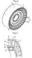
- Figs. 1 and 2 show a bearing with a pulley according to the present invention.
- the bearing with the pulley comprises a rolling bearing 1, an radially inner cylindrical portion 3 fixed to an outer race 2 of the rolling bearing 1, a radially outer cylindrical portion 5 having a belt guide surface 4, a disk portion 6 formed between the radially inner and outer cylindrical portions 3 and 5, and a plurality of radial ribs 7 formed on the disk portion 6.
- the bearing with the pulley is manufactured in a pulley forming mold 9 formed with a cavity 8 having a shape complementary to the pulley.
- This mold 9 has six gate holes 10 at positions corresponding to the radially inner cylindrical portion 3 of the pulley. Molten resin is injected into the cavity 8 through the gate holes 10.
- the gate holes 10 are formed so as to be rotationally asymmetric around the rotation axis of the pulley.
- the gate holes 10 are formed so as to be rotationally asymmetric, at least one or some of the gate holes 10 have a different diameter from other gate holes 10.
- resin supplied through the respective gate holes 10 reaches positions in the cavity 8 corresponding to the radially outer cylindrical portion 5, not simultaneously, but with a time delay.
- the resins at the respective positions corresponding to the radially outer cylindrical portion 5 shrink at different rates, thus making the outer diameter of the radially outer cylindrical portion 5 rotationally asymmetric.
- not all the ribs 7 are equal in thickness to one another, but at least one or some (e.g. 7a of Fig. 1 ) are thicker than others (e.g. 7b of Fig. 1 ). Portions of the resin injected into the cavity through the gate holes 10 pass between the adjacent ribs 7 and are supplied to the radially outer cylindrical portion 5. Since not all the ribs 7 are equal in thickness, the portions of the resin that flow between thicker ribs 7 flow at a different speed from the portions of the resin that flow between thinner ribs 7. This makes the outer diameter of the radially outer cylindrical portion 5 rotationally asymmetric.
- injection marks 11 of resin injected through the gate holes 10 remain.
- the injection marks 11 positionally correspond to the respective gate holes 10.
- the injection marks 11 are arranged so as to be rotationally asymmetric, and also at least one or some of the injection marks 11 have a different diameter from other injection marks 11. Because these injection marks 11 do not serve any particular purpose, they may be removed by e.g. grinding or may be left as they are.
- the following three means are employed: (1) the gate holes 10 are arranged so as to be rotationally asymmetric; (2) at least one or some of the gate holes 10 have a different diameter from other gate holes 10; and (3) at least one or some of the ribs 7 have a different thickness from other ribs 7. But instead, not all three but only one or two of the above three means may be employed, because any one of the three means can independently achieve the object of the present invention.
- the radially outer cylindrical portion 5 may be ground or otherwise machined.
- the pulley is integral with the outer race 2 of the rolling bearing.
- a rotary shaft may be directly fitted in the radially inner cylindrical portion 3 of the pulley. In this arrangement too, it is possible to suppress beating sounds of the pulley.
- the bearing with the pulley shown e.g. in Fig. 1 includes 36 ribs 7 and nine gate holes 10. But their numbers are not limited provided the object of the invention is achieved.
- the number of ribs 7 may not be a multiple of the number of the gate holes 10 (such as 32 ribs and 6 gate holes); or the number or ribs 7 may be a prime number, i.e. a number whose factors are only 1 and itself (such as 31 ribs and 7 gate holes).
Landscapes
- Engineering & Computer Science (AREA)
- General Engineering & Computer Science (AREA)
- Mechanical Engineering (AREA)
- Manufacturing & Machinery (AREA)
- Pulleys (AREA)
- Moulds For Moulding Plastics Or The Like (AREA)
Claims (8)
- Procédé de fabrication d'une poulie comprenant une partie cylindrique radialement interne (3) fixée à une cage externe (2) d'un palier à roulement (1), une partie cylindrique radialement externe (5) comportant une surface de guidage de courroie (4), une partie de disque (6) formée entre les parties cylindriques radialement interne et externe (3, 5) et une pluralité de nervures radiales (7) formées sur la partie de disque (6), dans lequel la partie cylindrique radialement externe (5) possède un diamètre externe qui est asymétrique en rotation autour de l'axe de rotation de la poulie,
comprenant les étapes consistant à
injecter un matériau fondu dans un moule (9) par des trous d'entrée (10) formés dans le moule (9) de façon à être asymétrique en rotation autour de l'axe de rotation et faire durcir le matériau fondu dans le moule (9),
caractérisé par l'étape consistant à :injecter le matériau fondu dans un moule (9) par l'intermédiaire des trous d'entrée (10) agencés de telle sorte qu'au moins un ou plusieurs des trous d'entrée (10) ait un diamètre différent de celui des autres trous d'entrée (10). - Poulie formée par un procédé selon la revendication 1, dans laquelle la poulie comporte des marques d'injection (11) correspondant en position aux trous d'entrée respectifs (10).
- Poulie selon la revendication 2, dans laquelle le nombre de nervures (7) n'est pas un multiple du nombre de marques d'injections (11).
- Poulie selon la revendication 2, dans laquelle le nombre de nervures (7) est un nombre premier qui est différent du nombre de marques d'injections (11).
- Poulie selon l'une quelconque des revendications 2 à 4, dans laquelle toutes les nervures (7) n'ont pas la même épaisseur.
- Poulie selon l'une quelconque des revendications 2 à 5, faite d'une résine.
- Palier à roulement comportant la poulie selon l'une quelconque des revendications 2 à 6, dans lequel le palier à roulement (1) comporte une cage externe (2), et dans lequel la poulie est formée de manière intégrée sur la cage externe (2) par moulage par injection d'une résine.
- Moule pour mettre en oeuvre un procédé selon la revendication 1, dans lequel ledit moule (9) comporte une cavité (8), sa forme étant complémentaire à celle de la poulie, dans lequel ledit moule (9) comporte des trous d'entrée (10) formés dans le moule (9) de façon à être asymétrique en rotation autour de l'axe de rotation et pour injecter un matériau fondu, et dans lequel au moins un ou certains des trous d'entrée (10) ont un diamètre différent de celui des autres trous d'entrée (10).
Applications Claiming Priority (2)
| Application Number | Priority Date | Filing Date | Title |
|---|---|---|---|
| JP2008260499A JP5189453B2 (ja) | 2008-10-07 | 2008-10-07 | プーリ及び樹脂プーリ付き転がり軸受 |
| JP2008284202A JP5483145B2 (ja) | 2008-11-05 | 2008-11-05 | プーリ及び樹脂プーリ付き転がり軸受 |
Publications (3)
| Publication Number | Publication Date |
|---|---|
| EP2175169A2 EP2175169A2 (fr) | 2010-04-14 |
| EP2175169A3 EP2175169A3 (fr) | 2011-12-07 |
| EP2175169B1 true EP2175169B1 (fr) | 2013-11-06 |
Family
ID=41479628
Family Applications (1)
| Application Number | Title | Priority Date | Filing Date |
|---|---|---|---|
| EP09170782.8A Not-in-force EP2175169B1 (fr) | 2008-10-07 | 2009-09-21 | Poulie et palier à roulement doté d'une poulie en résine |
Country Status (1)
| Country | Link |
|---|---|
| EP (1) | EP2175169B1 (fr) |
Families Citing this family (2)
| Publication number | Priority date | Publication date | Assignee | Title |
|---|---|---|---|---|
| DE102013005373B4 (de) | 2013-03-28 | 2016-07-07 | Schaeffler Technologies AG & Co. KG | Riemenrolle und Verfahren zu deren Herstellung |
| DE102014217491B4 (de) * | 2014-09-02 | 2017-11-16 | Schaeffler Technologies AG & Co. KG | Riemenscheibe und Kunststoff-Spritzgießverfahren zu deren Herstellung |
Family Cites Families (9)
| Publication number | Priority date | Publication date | Assignee | Title |
|---|---|---|---|---|
| JPH0225962Y2 (fr) * | 1984-11-12 | 1990-07-16 | ||
| JP2881223B2 (ja) | 1990-05-29 | 1999-04-12 | 光洋精工株式会社 | 樹脂製プーリ |
| JPH0614609U (ja) * | 1992-07-29 | 1994-02-25 | エヌティエヌ株式会社 | 合成樹脂製プーリ |
| DE9319394U1 (de) * | 1993-12-17 | 1994-02-10 | Bayerische Motoren Werke AG, 80809 München | Spannrolle für einen Riementrieb |
| JP2000161472A (ja) * | 1998-11-30 | 2000-06-16 | Shin Kobe Electric Mach Co Ltd | 樹脂製プーリ |
| DE19937681C2 (de) * | 1999-08-10 | 2001-11-08 | Opel Adam Ag | Spannrolle für einen Riementrieb |
| DE10360290B4 (de) * | 2003-12-20 | 2010-07-29 | Schaeffler Technologies Gmbh & Co. Kg | Kunststoffummantelte Rolle, insbesondere Spannrolle für einen Riementrieb |
| JP2008149502A (ja) | 2006-12-15 | 2008-07-03 | Sekisui Techno Seikei Kk | 射出成形回転体 |
| DE102007017882A1 (de) * | 2007-04-13 | 2008-12-18 | Muhr Und Bender Kg | Laufrolle mit abgeschwächtem Anregungsverhalten |
-
2009
- 2009-09-21 EP EP09170782.8A patent/EP2175169B1/fr not_active Not-in-force
Also Published As
| Publication number | Publication date |
|---|---|
| EP2175169A3 (fr) | 2011-12-07 |
| EP2175169A2 (fr) | 2010-04-14 |
Similar Documents
| Publication | Publication Date | Title |
|---|---|---|
| JP4173053B2 (ja) | 射出成形樹脂歯車、射出成形樹脂スプロケット、射出成形樹脂プーリ、射出成形樹脂ローラ | |
| EP2414689B1 (fr) | Poulie de renvoi, palier et leur procédé de fabrication | |
| EP2091131B1 (fr) | Rotor aux aimants permanents pour un moteur et son procédé de fabrication | |
| US6070484A (en) | Mold type plastic gear | |
| JP2009541679A (ja) | ねじ歯車 | |
| KR20150088189A (ko) | 다부재 기어 | |
| CN101205967A (zh) | 树脂齿轮 | |
| KR20080102214A (ko) | 기어 휠 | |
| EP2175169B1 (fr) | Poulie et palier à roulement doté d'une poulie en résine | |
| US7069805B2 (en) | Driving force transmission device | |
| US9841096B2 (en) | Belt pulley and method for producing it | |
| JP2009040013A (ja) | 回転伝達手段及び回転伝達手段の射出成形金型 | |
| JP2880564B2 (ja) | 樹脂製プーリ | |
| KR20010026882A (ko) | 자동차용 플라스틱 댐퍼 풀리 및 이것의 제조방법 | |
| JP2005195116A (ja) | プーリ装置 | |
| JP2014234907A (ja) | プーリ装置 | |
| JP5483145B2 (ja) | プーリ及び樹脂プーリ付き転がり軸受 | |
| JP5899644B2 (ja) | プーリ装置 | |
| JP2001090811A (ja) | プーリ | |
| JP4186205B2 (ja) | 樹脂プーリ付き軸受 | |
| JP2011137517A (ja) | 樹脂製プーリ | |
| JP4104318B2 (ja) | 合成樹脂歯車 | |
| JP4860650B2 (ja) | 合成樹脂成形品 | |
| JP4269530B2 (ja) | 樹脂プーリ付き軸受およびその製造方法 | |
| JP7725212B2 (ja) | 射出成形体 |
Legal Events
| Date | Code | Title | Description |
|---|---|---|---|
| PUAI | Public reference made under article 153(3) epc to a published international application that has entered the european phase |
Free format text: ORIGINAL CODE: 0009012 |
|
| AK | Designated contracting states |
Kind code of ref document: A2 Designated state(s): AT BE BG CH CY CZ DE DK EE ES FI FR GB GR HR HU IE IS IT LI LT LU LV MC MK MT NL NO PL PT RO SE SI SK SM TR |
|
| AX | Request for extension of the european patent |
Extension state: AL BA RS |
|
| PUAL | Search report despatched |
Free format text: ORIGINAL CODE: 0009013 |
|
| AK | Designated contracting states |
Kind code of ref document: A3 Designated state(s): AT BE BG CH CY CZ DE DK EE ES FI FR GB GR HR HU IE IS IT LI LT LU LV MC MK MT NL NO PL PT RO SE SI SK SM TR |
|
| AX | Request for extension of the european patent |
Extension state: AL BA RS |
|
| RIC1 | Information provided on ipc code assigned before grant |
Ipc: F16H 55/40 20060101ALN20111031BHEP Ipc: F16C 13/00 20060101ALN20111031BHEP Ipc: F16H 55/48 20060101AFI20111031BHEP |
|
| 17P | Request for examination filed |
Effective date: 20120521 |
|
| 17Q | First examination report despatched |
Effective date: 20120627 |
|
| GRAP | Despatch of communication of intention to grant a patent |
Free format text: ORIGINAL CODE: EPIDOSNIGR1 |
|
| RIC1 | Information provided on ipc code assigned before grant |
Ipc: F16C 35/067 20060101ALN20121107BHEP Ipc: F16H 55/48 20060101AFI20121107BHEP Ipc: F16H 55/40 20060101ALN20121107BHEP Ipc: F16C 13/00 20060101ALN20121107BHEP |
|
| GRAS | Grant fee paid |
Free format text: ORIGINAL CODE: EPIDOSNIGR3 |
|
| GRAP | Despatch of communication of intention to grant a patent |
Free format text: ORIGINAL CODE: EPIDOSNIGR1 |
|
| INTG | Intention to grant announced |
Effective date: 20130418 |
|
| RIC1 | Information provided on ipc code assigned before grant |
Ipc: F16C 35/067 20060101ALN20130410BHEP Ipc: F16C 13/00 20060101ALN20130410BHEP Ipc: F16H 55/40 20060101ALN20130410BHEP Ipc: F16H 55/48 20060101AFI20130410BHEP |
|
| GRAA | (expected) grant |
Free format text: ORIGINAL CODE: 0009210 |
|
| AK | Designated contracting states |
Kind code of ref document: B1 Designated state(s): AT BE BG CH CY CZ DE DK EE ES FI FR GB GR HR HU IE IS IT LI LT LU LV MC MK MT NL NO PL PT RO SE SI SK SM TR |
|
| REG | Reference to a national code |
Ref country code: GB Ref legal event code: FG4D |
|
| REG | Reference to a national code |
Ref country code: CH Ref legal event code: EP |
|
| REG | Reference to a national code |
Ref country code: AT Ref legal event code: REF Ref document number: 639720 Country of ref document: AT Kind code of ref document: T Effective date: 20131215 |
|
| REG | Reference to a national code |
Ref country code: IE Ref legal event code: FG4D |
|
| REG | Reference to a national code |
Ref country code: DE Ref legal event code: R096 Ref document number: 602009019856 Country of ref document: DE Effective date: 20140102 |
|
| REG | Reference to a national code |
Ref country code: NL Ref legal event code: VDEP Effective date: 20131106 |
|
| REG | Reference to a national code |
Ref country code: AT Ref legal event code: MK05 Ref document number: 639720 Country of ref document: AT Kind code of ref document: T Effective date: 20131106 |
|
| REG | Reference to a national code |
Ref country code: LT Ref legal event code: MG4D |
|
| PG25 | Lapsed in a contracting state [announced via postgrant information from national office to epo] |
Ref country code: IS Free format text: LAPSE BECAUSE OF FAILURE TO SUBMIT A TRANSLATION OF THE DESCRIPTION OR TO PAY THE FEE WITHIN THE PRESCRIBED TIME-LIMIT Effective date: 20140306 Ref country code: HR Free format text: LAPSE BECAUSE OF FAILURE TO SUBMIT A TRANSLATION OF THE DESCRIPTION OR TO PAY THE FEE WITHIN THE PRESCRIBED TIME-LIMIT Effective date: 20131106 Ref country code: LT Free format text: LAPSE BECAUSE OF FAILURE TO SUBMIT A TRANSLATION OF THE DESCRIPTION OR TO PAY THE FEE WITHIN THE PRESCRIBED TIME-LIMIT Effective date: 20131106 Ref country code: SE Free format text: LAPSE BECAUSE OF FAILURE TO SUBMIT A TRANSLATION OF THE DESCRIPTION OR TO PAY THE FEE WITHIN THE PRESCRIBED TIME-LIMIT Effective date: 20131106 Ref country code: NL Free format text: LAPSE BECAUSE OF FAILURE TO SUBMIT A TRANSLATION OF THE DESCRIPTION OR TO PAY THE FEE WITHIN THE PRESCRIBED TIME-LIMIT Effective date: 20131106 Ref country code: NO Free format text: LAPSE BECAUSE OF FAILURE TO SUBMIT A TRANSLATION OF THE DESCRIPTION OR TO PAY THE FEE WITHIN THE PRESCRIBED TIME-LIMIT Effective date: 20140206 Ref country code: FI Free format text: LAPSE BECAUSE OF FAILURE TO SUBMIT A TRANSLATION OF THE DESCRIPTION OR TO PAY THE FEE WITHIN THE PRESCRIBED TIME-LIMIT Effective date: 20131106 |
|
| PG25 | Lapsed in a contracting state [announced via postgrant information from national office to epo] |
Ref country code: BE Free format text: LAPSE BECAUSE OF FAILURE TO SUBMIT A TRANSLATION OF THE DESCRIPTION OR TO PAY THE FEE WITHIN THE PRESCRIBED TIME-LIMIT Effective date: 20131106 Ref country code: AT Free format text: LAPSE BECAUSE OF FAILURE TO SUBMIT A TRANSLATION OF THE DESCRIPTION OR TO PAY THE FEE WITHIN THE PRESCRIBED TIME-LIMIT Effective date: 20131106 Ref country code: LV Free format text: LAPSE BECAUSE OF FAILURE TO SUBMIT A TRANSLATION OF THE DESCRIPTION OR TO PAY THE FEE WITHIN THE PRESCRIBED TIME-LIMIT Effective date: 20131106 Ref country code: ES Free format text: LAPSE BECAUSE OF FAILURE TO SUBMIT A TRANSLATION OF THE DESCRIPTION OR TO PAY THE FEE WITHIN THE PRESCRIBED TIME-LIMIT Effective date: 20131106 |
|
| PG25 | Lapsed in a contracting state [announced via postgrant information from national office to epo] |
Ref country code: PT Free format text: LAPSE BECAUSE OF FAILURE TO SUBMIT A TRANSLATION OF THE DESCRIPTION OR TO PAY THE FEE WITHIN THE PRESCRIBED TIME-LIMIT Effective date: 20140306 |
|
| PG25 | Lapsed in a contracting state [announced via postgrant information from national office to epo] |
Ref country code: EE Free format text: LAPSE BECAUSE OF FAILURE TO SUBMIT A TRANSLATION OF THE DESCRIPTION OR TO PAY THE FEE WITHIN THE PRESCRIBED TIME-LIMIT Effective date: 20131106 |
|
| REG | Reference to a national code |
Ref country code: DE Ref legal event code: R097 Ref document number: 602009019856 Country of ref document: DE |
|
| PG25 | Lapsed in a contracting state [announced via postgrant information from national office to epo] |
Ref country code: PL Free format text: LAPSE BECAUSE OF FAILURE TO SUBMIT A TRANSLATION OF THE DESCRIPTION OR TO PAY THE FEE WITHIN THE PRESCRIBED TIME-LIMIT Effective date: 20131106 Ref country code: RO Free format text: LAPSE BECAUSE OF FAILURE TO SUBMIT A TRANSLATION OF THE DESCRIPTION OR TO PAY THE FEE WITHIN THE PRESCRIBED TIME-LIMIT Effective date: 20131106 Ref country code: CZ Free format text: LAPSE BECAUSE OF FAILURE TO SUBMIT A TRANSLATION OF THE DESCRIPTION OR TO PAY THE FEE WITHIN THE PRESCRIBED TIME-LIMIT Effective date: 20131106 Ref country code: SK Free format text: LAPSE BECAUSE OF FAILURE TO SUBMIT A TRANSLATION OF THE DESCRIPTION OR TO PAY THE FEE WITHIN THE PRESCRIBED TIME-LIMIT Effective date: 20131106 |
|
| PLBE | No opposition filed within time limit |
Free format text: ORIGINAL CODE: 0009261 |
|
| STAA | Information on the status of an ep patent application or granted ep patent |
Free format text: STATUS: NO OPPOSITION FILED WITHIN TIME LIMIT |
|
| PG25 | Lapsed in a contracting state [announced via postgrant information from national office to epo] |
Ref country code: DK Free format text: LAPSE BECAUSE OF FAILURE TO SUBMIT A TRANSLATION OF THE DESCRIPTION OR TO PAY THE FEE WITHIN THE PRESCRIBED TIME-LIMIT Effective date: 20131106 |
|
| 26N | No opposition filed |
Effective date: 20140807 |
|
| REG | Reference to a national code |
Ref country code: DE Ref legal event code: R097 Ref document number: 602009019856 Country of ref document: DE Effective date: 20140807 |
|
| PG25 | Lapsed in a contracting state [announced via postgrant information from national office to epo] |
Ref country code: SI Free format text: LAPSE BECAUSE OF FAILURE TO SUBMIT A TRANSLATION OF THE DESCRIPTION OR TO PAY THE FEE WITHIN THE PRESCRIBED TIME-LIMIT Effective date: 20131106 |
|
| REG | Reference to a national code |
Ref country code: DE Ref legal event code: R119 Ref document number: 602009019856 Country of ref document: DE |
|
| PG25 | Lapsed in a contracting state [announced via postgrant information from national office to epo] |
Ref country code: LU Free format text: LAPSE BECAUSE OF FAILURE TO SUBMIT A TRANSLATION OF THE DESCRIPTION OR TO PAY THE FEE WITHIN THE PRESCRIBED TIME-LIMIT Effective date: 20140921 Ref country code: MC Free format text: LAPSE BECAUSE OF FAILURE TO SUBMIT A TRANSLATION OF THE DESCRIPTION OR TO PAY THE FEE WITHIN THE PRESCRIBED TIME-LIMIT Effective date: 20131106 |
|
| REG | Reference to a national code |
Ref country code: CH Ref legal event code: PL |
|
| GBPC | Gb: european patent ceased through non-payment of renewal fee |
Effective date: 20140921 |
|
| REG | Reference to a national code |
Ref country code: IE Ref legal event code: MM4A |
|
| REG | Reference to a national code |
Ref country code: DE Ref legal event code: R119 Ref document number: 602009019856 Country of ref document: DE Effective date: 20150401 |
|
| REG | Reference to a national code |
Ref country code: FR Ref legal event code: ST Effective date: 20150529 |
|
| PG25 | Lapsed in a contracting state [announced via postgrant information from national office to epo] |
Ref country code: DE Free format text: LAPSE BECAUSE OF NON-PAYMENT OF DUE FEES Effective date: 20150401 Ref country code: GB Free format text: LAPSE BECAUSE OF NON-PAYMENT OF DUE FEES Effective date: 20140921 Ref country code: LI Free format text: LAPSE BECAUSE OF NON-PAYMENT OF DUE FEES Effective date: 20140930 Ref country code: CH Free format text: LAPSE BECAUSE OF NON-PAYMENT OF DUE FEES Effective date: 20140930 |
|
| REG | Reference to a national code |
Ref country code: DE Ref legal event code: R073 Ref document number: 602009019856 Country of ref document: DE Ref country code: FR Ref legal event code: PLFP Year of fee payment: 7 |
|
| PG25 | Lapsed in a contracting state [announced via postgrant information from national office to epo] |
Ref country code: IE Free format text: LAPSE BECAUSE OF NON-PAYMENT OF DUE FEES Effective date: 20140921 Ref country code: IT Free format text: LAPSE BECAUSE OF NON-PAYMENT OF DUE FEES Effective date: 20140921 Ref country code: FR Free format text: LAPSE BECAUSE OF NON-PAYMENT OF DUE FEES Effective date: 20140930 |
|
| REG | Reference to a national code |
Ref country code: DE Ref legal event code: R074 Ref document number: 602009019856 Country of ref document: DE |
|
| REG | Reference to a national code |
Ref country code: FR Ref legal event code: RN Effective date: 20150821 |
|
| REG | Reference to a national code |
Ref country code: FR Ref legal event code: FC Effective date: 20150910 |
|
| PGRI | Patent reinstated in contracting state [announced from national office to epo] |
Ref country code: DE Effective date: 20150916 |
|
| PGRI | Patent reinstated in contracting state [announced from national office to epo] |
Ref country code: FR Effective date: 20151204 |
|
| PG25 | Lapsed in a contracting state [announced via postgrant information from national office to epo] |
Ref country code: SM Free format text: LAPSE BECAUSE OF FAILURE TO SUBMIT A TRANSLATION OF THE DESCRIPTION OR TO PAY THE FEE WITHIN THE PRESCRIBED TIME-LIMIT Effective date: 20131106 |
|
| PG25 | Lapsed in a contracting state [announced via postgrant information from national office to epo] |
Ref country code: CY Free format text: LAPSE BECAUSE OF FAILURE TO SUBMIT A TRANSLATION OF THE DESCRIPTION OR TO PAY THE FEE WITHIN THE PRESCRIBED TIME-LIMIT Effective date: 20131106 Ref country code: BG Free format text: LAPSE BECAUSE OF FAILURE TO SUBMIT A TRANSLATION OF THE DESCRIPTION OR TO PAY THE FEE WITHIN THE PRESCRIBED TIME-LIMIT Effective date: 20131106 Ref country code: GR Free format text: LAPSE BECAUSE OF FAILURE TO SUBMIT A TRANSLATION OF THE DESCRIPTION OR TO PAY THE FEE WITHIN THE PRESCRIBED TIME-LIMIT Effective date: 20140207 Ref country code: MT Free format text: LAPSE BECAUSE OF FAILURE TO SUBMIT A TRANSLATION OF THE DESCRIPTION OR TO PAY THE FEE WITHIN THE PRESCRIBED TIME-LIMIT Effective date: 20131106 |
|
| PG25 | Lapsed in a contracting state [announced via postgrant information from national office to epo] |
Ref country code: HU Free format text: LAPSE BECAUSE OF FAILURE TO SUBMIT A TRANSLATION OF THE DESCRIPTION OR TO PAY THE FEE WITHIN THE PRESCRIBED TIME-LIMIT; INVALID AB INITIO Effective date: 20090921 Ref country code: TR Free format text: LAPSE BECAUSE OF FAILURE TO SUBMIT A TRANSLATION OF THE DESCRIPTION OR TO PAY THE FEE WITHIN THE PRESCRIBED TIME-LIMIT Effective date: 20131106 |
|
| REG | Reference to a national code |
Ref country code: FR Ref legal event code: PLFP Year of fee payment: 8 |
|
| REG | Reference to a national code |
Ref country code: FR Ref legal event code: PLFP Year of fee payment: 9 |
|
| PG25 | Lapsed in a contracting state [announced via postgrant information from national office to epo] |
Ref country code: MK Free format text: LAPSE BECAUSE OF FAILURE TO SUBMIT A TRANSLATION OF THE DESCRIPTION OR TO PAY THE FEE WITHIN THE PRESCRIBED TIME-LIMIT Effective date: 20131106 |
|
| REG | Reference to a national code |
Ref country code: FR Ref legal event code: PLFP Year of fee payment: 10 |
|
| PG25 | Lapsed in a contracting state [announced via postgrant information from national office to epo] |
Ref country code: IT Free format text: LAPSE BECAUSE OF NON-PAYMENT OF DUE FEES Effective date: 20140921 |
|
| PGRI | Patent reinstated in contracting state [announced from national office to epo] |
Ref country code: IT Effective date: 20180810 |
|
| PGFP | Annual fee paid to national office [announced via postgrant information from national office to epo] |
Ref country code: IT Payment date: 20190917 Year of fee payment: 11 Ref country code: DE Payment date: 20190910 Year of fee payment: 11 Ref country code: FR Payment date: 20190815 Year of fee payment: 11 |
|
| REG | Reference to a national code |
Ref country code: DE Ref legal event code: R119 Ref document number: 602009019856 Country of ref document: DE |
|
| PG25 | Lapsed in a contracting state [announced via postgrant information from national office to epo] |
Ref country code: DE Free format text: LAPSE BECAUSE OF NON-PAYMENT OF DUE FEES Effective date: 20210401 Ref country code: FR Free format text: LAPSE BECAUSE OF NON-PAYMENT OF DUE FEES Effective date: 20200930 |
|
| PG25 | Lapsed in a contracting state [announced via postgrant information from national office to epo] |
Ref country code: IT Free format text: LAPSE BECAUSE OF NON-PAYMENT OF DUE FEES Effective date: 20200921 |