EP2175197A2 - Procédé de traitement des gaz d'échappement par postcombustion regénérative - Google Patents
Procédé de traitement des gaz d'échappement par postcombustion regénérative Download PDFInfo
- Publication number
- EP2175197A2 EP2175197A2 EP09170299A EP09170299A EP2175197A2 EP 2175197 A2 EP2175197 A2 EP 2175197A2 EP 09170299 A EP09170299 A EP 09170299A EP 09170299 A EP09170299 A EP 09170299A EP 2175197 A2 EP2175197 A2 EP 2175197A2
- Authority
- EP
- European Patent Office
- Prior art keywords
- exhaust gases
- gas
- burner
- combustion
- exhaust
- Prior art date
- Legal status (The legal status is an assumption and is not a legal conclusion. Google has not performed a legal analysis and makes no representation as to the accuracy of the status listed.)
- Granted
Links
Images
Classifications
-
- F—MECHANICAL ENGINEERING; LIGHTING; HEATING; WEAPONS; BLASTING
- F23—COMBUSTION APPARATUS; COMBUSTION PROCESSES
- F23G—CREMATION FURNACES; CONSUMING WASTE PRODUCTS BY COMBUSTION
- F23G7/00—Incinerators or other apparatus for consuming industrial waste, e.g. chemicals
- F23G7/06—Incinerators or other apparatus for consuming industrial waste, e.g. chemicals of waste gases or noxious gases, e.g. exhaust gases
- F23G7/07—Incinerators or other apparatus for consuming industrial waste, e.g. chemicals of waste gases or noxious gases, e.g. exhaust gases in which combustion takes place in the presence of catalytic material
-
- F—MECHANICAL ENGINEERING; LIGHTING; HEATING; WEAPONS; BLASTING
- F23—COMBUSTION APPARATUS; COMBUSTION PROCESSES
- F23G—CREMATION FURNACES; CONSUMING WASTE PRODUCTS BY COMBUSTION
- F23G5/00—Incineration of waste; Incinerator constructions; Details, accessories or control therefor
- F23G5/50—Control or safety arrangements
-
- F—MECHANICAL ENGINEERING; LIGHTING; HEATING; WEAPONS; BLASTING
- F23—COMBUSTION APPARATUS; COMBUSTION PROCESSES
- F23G—CREMATION FURNACES; CONSUMING WASTE PRODUCTS BY COMBUSTION
- F23G7/00—Incinerators or other apparatus for consuming industrial waste, e.g. chemicals
- F23G7/06—Incinerators or other apparatus for consuming industrial waste, e.g. chemicals of waste gases or noxious gases, e.g. exhaust gases
- F23G7/061—Incinerators or other apparatus for consuming industrial waste, e.g. chemicals of waste gases or noxious gases, e.g. exhaust gases with supplementary heating
- F23G7/065—Incinerators or other apparatus for consuming industrial waste, e.g. chemicals of waste gases or noxious gases, e.g. exhaust gases with supplementary heating using gaseous or liquid fuel
-
- F—MECHANICAL ENGINEERING; LIGHTING; HEATING; WEAPONS; BLASTING
- F23—COMBUSTION APPARATUS; COMBUSTION PROCESSES
- F23G—CREMATION FURNACES; CONSUMING WASTE PRODUCTS BY COMBUSTION
- F23G2202/00—Combustion
- F23G2202/60—Combustion in a catalytic combustion chamber
-
- F—MECHANICAL ENGINEERING; LIGHTING; HEATING; WEAPONS; BLASTING
- F23—COMBUSTION APPARATUS; COMBUSTION PROCESSES
- F23G—CREMATION FURNACES; CONSUMING WASTE PRODUCTS BY COMBUSTION
- F23G2207/00—Control
- F23G2207/10—Arrangement of sensing devices
- F23G2207/101—Arrangement of sensing devices for temperature
-
- F—MECHANICAL ENGINEERING; LIGHTING; HEATING; WEAPONS; BLASTING
- F23—COMBUSTION APPARATUS; COMBUSTION PROCESSES
- F23G—CREMATION FURNACES; CONSUMING WASTE PRODUCTS BY COMBUSTION
- F23G2207/00—Control
- F23G2207/30—Oxidant supply
-
- F—MECHANICAL ENGINEERING; LIGHTING; HEATING; WEAPONS; BLASTING
- F23—COMBUSTION APPARATUS; COMBUSTION PROCESSES
- F23G—CREMATION FURNACES; CONSUMING WASTE PRODUCTS BY COMBUSTION
- F23G2207/00—Control
- F23G2207/60—Additives supply
Definitions
- the present invention relates to a method for purifying exhaust gases by generative afterburning.
- An oxygen-free exhaust gas with combustible impurities such as occurs in hardening shops, is incinerated without prior heating or heat exchange in a combustion chamber and the resulting exhaust subsequently cleaned in a catalytic purification stage. Furthermore, an apparatus for carrying out the method is presented.
- exhaust gas is to be understood as meaning not only the exhaust gas of a combustion but also a pollutant-laden exhaust air from installations.
- the simplest method is burning in a torch.
- the exhaust gases to be cleaned are fed to an open flame and burned the ignitable components there.
- This method is characterized by a simple and inexpensive device that quickly reaches operational readiness during commissioning.
- the disadvantages that the exhaust gas must be ignitable the process is not regulated and compliance with the limit values for pollutants in the exhaust gas is not always guaranteed.
- TNV thermal afterburning
- the TNV has the drawback of a very high energy consumption, since the large amount of added air to heat a much larger amount of gas than the original exhaust gas to very high temperatures.
- downstream heat exchanger which in turn can preheat the exhaust gas before entering the combustion chamber, the efficiency can be improved, but since the preheating may only be so high that no reaction takes place in the heat exchanger, is still a considerable amount of energy to spend.
- the production costs of a TNV plant are higher, as higher material costs are incurred due to the high process temperatures (eg for high temperature resistant steels).
- DE 2 026 237 A1 Exemplary of the innumerable thermal post-combustion plants described in the technical and patent literature are here DE 2 026 237 A1 and WO 87/05090 A1 called.
- DE 2 026 237 A1 a method and apparatus for thermal post-combustion of exhaust air from industrial plants is described, in which the exhaust air is preferably preheated under elevated pressure through one or more heat exchangers, then introduced into a combustion chamber, there first flows through another heat exchanger and then burned in a burner becomes. The hot combustion gases then pass through the heat exchangers in reverse order before being released into the open. Part of the amount of exhaust gas burned is returned in the combustion chamber to increase the degree of conversion of the impurities.
- WO 87/05090 A1 discloses a method and a device for the thermal burning of oxidizable constituents in a process gas, which is characterized in that the exhaust gas is preheated by a heat exchanger, which is traversed by the purified exhaust gas and then by means of a burner in a combustion chamber, wherein the exhaust gas to be purified before the entry into the afterburner in addition to the required fresh air and an amount of purified exhaust gas is supplied, that the concentration of oxidizable constituents in the incoming gas stream is kept constant.
- An advancement of the TNV is the catalytic afterburning (KNV).
- KNV catalytic afterburning
- the temperature required for the safe conversion of the hydrocarbons is lowered by the use of a catalytic purification stage.
- the exhaust gas to be cleaned is heated to 250-400 ° C. with the aid of heat exchangers and optionally an auxiliary heater or an additional burner.
- dilution of the supplied exhaust gases with air to a concentration of the combustible constituents of less than 25% of the lower explosion limit must be carried out again.
- the advantages of the KNV are the same as those of the TNV, whereby the energy consumption is significantly lower.
- Regenerative afterburning is a TNV or KNV with "integrated" heat recovery.
- the heat content of the purified waste gas is stored in a heat storage mass that is located directly in the oxidation zone and is therefore directly involved in the oxidation process to disposal.
- ceramic packed beds are used for this, which enable a good efficiency of heat transfer with low pressure loss.
- thermal afterburning the bed is filled with inert bulk material while the catalytic afterburning unit is charged with an appropriate catalyst charge. At least two such beds are operated in cyclic alternation, wherein a hot bed for preheating the exhaust gas is flowed through by this and thereby cools and the second cold bed is heated by the oxidation of the exhaust gases.
- the oxygen in the cooling air which is supplied in the catalyst, in this case participates in the reaction. Due to the good heat recovery within the system, an autothermal mode of operation can be achieved in catalytic systems even at low concentrations of hydrocarbons. However, this advantage is associated with a high expenditure on equipment with a correspondingly large space requirement.
- the use of valves that lock hot gases requires increased maintenance. Due to the long heat-up time, which require the heat storage, the operational readiness of such a system is reached only slowly. Therefore, these systems are unsuitable for sporadic or short-term use and useful only in continuous operation.
- a device for thermal exhaust gas treatment in particular of oxidizable carbonization gases is presented, which comprises a regenerator unit with at least two regenerators each having a heat storage and a heating zone arranged between the regenerators and a buffer cell.
- the exhaust gas stream to be cleaned can be fed alternately from one side of a series arrangement of at least two regenerators, wherein the remaining during the switching uncleaned in the regenerators exhaust gas in a buffer cell, which is heated by the purified exhaust gas stream is stored, and after completion of the switching operation the input current again is added.
- the object of the present invention is to provide a method for exhaust gas cleaning available, the cleaning of oxygen-free exhaust gases in a compact design with low space requirements with minimal energy consumption high concentrations of combustible components, such as those incurred in exhaust gases from hardening shops.
- concentration of combustible constituents can be up to 100% by volume in these.
- oxygen-free exhaust gases are to be understood as those exhaust gases which contain no oxygen, which is ensured by a permanent oxygen analysis.
- the exhaust gases to be treated may consist of 100 vol .-% of combustible constituents, contain in a preferred embodiment of the invention, however, at least 0 vol .-%, preferably at least 10 vol .-%, more preferably at least 20 vol .-% combustible fractions.
- the exhaust gases are mixed with natural gas before combustion in the burner in order to promote oxidation.
- the amount of natural gas added depends on the content of the combustible components in the exhaust gas.
- the addition of the natural gas by means of an automatic control, which ensures that a temperature is maintained in the combustion chamber, which is high enough for the subsequent catalytic purification stage.
- the flame temperature of the burner is preferably maintained in the range of 600-1200 ° C, more preferably in the range of 800-1000 ° C.
- the catalytic purification stage is preferably operated at 300-650 ° C., more preferably at 400-530 ° C.
- the regulation of the natural gas supply into the burner takes place as a function of the temperature in the combustion chamber and / or the temperature at the inlet into the catalyst. Decreases at a constant supply of combustion air and cooling air, the temperature in the combustion chamber or at the catalyst inlet, the natural gas supply is increased because less combustible components are present in the exhaust gas. If the temperature rises, less natural gas is added accordingly.
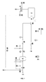
- a device for carrying out the method according to the invention which in the flowchart in Fig. 1 is shown with its essential functional elements, characterized in that it comprises an exhaust gas supply line (1), a natural gas supply line (2), an air supply line (3), one or more combustion chambers (7) with a burner connected thereto (6), an am Output of the combustion chamber installed catalytic purification stage (8) and has monitoring devices for the course of the combustion.
- a separate safety distance is provided for increasing the safety in the gas supply line for natural gas and the exhaust gas.
- the exhaust gas supply line is particularly preferably equipped with a gas buffer container (9), so that pressure and volume flow fluctuations in the exhaust gas stream to be cleaned can be compensated and not transferred to the burner (6). This ensures a more even combustion.
- the natural gas supply line (2) and the exhaust gas supply line (1) are brought together before entering the burner in a mixing chamber (33). Thereby, the mixing can be ensured even at higher inert gas in the exhaust gas.
- the burner is a blower burner with two fuel gas inlets. This allows the exhaust gas to be cleaned and the natural gas also supplied unmixed to the burner and only be mixed directly in the burner.
- the combustion air supply is preferably via a fan (in the air blower (34)) and / or via a valve (35) adjustable. Depending on the required flow rate, the control takes place via a valve or at higher throughputs via a fan. If necessary, both are adjustable for fine tuning.
- the monitoring devices are particularly preferably integrated into a total control with transducers. This enables efficient centralized control and monitoring.
- the components of the device are preferably transported separately as individual modules and can be built on site with connecting pipes and connections to the entire system.
- the connecting pipes are preferably equipped with a quick coupling system.
- the entire device can be transported as a compact unit in the build-up state. This makes it possible to make the emission control system quickly ready for use and, if necessary, to connect to an exhaust gas generating plant. Due to the compact design, this can also be done in confined spaces.
- the purified waste gas can be cooled by means of heat exchangers (not shown in the drawings) and the energy recovered from this via thermal oil and / or steam can be made available to other processes, since they are not suitable for preheating the exhaust gases to be cleaned is needed.
- the described method has several advantages: It allows very compact systems because of the small volume flows, since the admixture of air to the exhaust gas is eliminated. The air is first supplied to the burner, so that there is no explosive mixture before. Therefore, there are only minor requirements for explosion protection. Furthermore, this results in low system costs, low energy consumption and low maintenance costs. The operational readiness of the system can be achieved within a few minutes.
- the GNV works independently of the concentration of hydrocarbons in the exhaust gas.
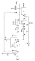
- the exhaust gas laden with combustible components passes via the solenoid valve (11) into the gas buffer container (9).
- the exhaust gas supply line (1) has a diameter of 25 mm in this embodiment.
- the exhaust gas has a maximum temperature of about 50 ° C and a pressure of about 1.3 bar.
- a permanent oxygen analysis (15) is performed.
- the gas buffer (9) is used to compensate for pressure and volume fluctuations in the exhaust gas.
- a pressure monitoring by means of PS + pressure switch (18) on the gas buffer container (9) ensures that from reaching a certain minimum pressure by opening the solenoid valve (12), the exhaust gas to be cleaned the burner (6) is supplied.
- the gas pressure is reduced by a pressure reducer (25) and kept constant.
- a pressure reducer Before entering the burner (6) is mixed with an amount of natural gas, which is sufficient to ensure stable combustion.
- both gas strands Prior to mixing, which can take place either in a mixing chamber (33) or directly through a pipe junction depending on the gases contained and volume flows through, both gas strands each pass through their own safety fittings section consisting of a pressure switch and redundancy reasons two solenoid valves (27, 28 and 29 , 30).
- the quantities of gas introduced into the mixing chamber (33) or the burner (6) are controlled by motor valves (19, 20) which are connected to the exhaust gas line by means of the pressure switches PS- (31) and PS + (32) and the natural gas line via the temperature regulator ( 23) which is arranged at the inlet of the catalytic purification stage (8).
- the engine valve (19) thus additionally ensures that the pressure is kept constant in the range set at the pressure switches (31) and (32). Especially when opening the solenoid valves (27, 28) so peaks in the energy input into the burner can be avoided.
- a corresponding safety circuit allows the opening of the solenoid valves (27, 28) only when the engine valve (19) is in its minimum position.
- the necessary for the combustion of the exhaust gases (oxidation of impurities) combustion air is metered in via the air supply line (3).
- the amount of air is adjusted so that it supplies the oxygen in approximately stoichiometric amount for the combustion of the design gas mixture to be expected from natural gas and exhaust gas.
- the regulation of the air supply can also take place via the fan of the air blower (34).
- An automatically controlled supply of cooling air into the combustion chamber (7) takes place via the engine valve (21).
- the temperature controller (23) which measures the inlet temperature at the catalytic purification stage (8), controls the engine valves (20, 21) accordingly to ensure stable combustion and the required inlet temperature for the catalyst.
- the temperature switch (22) is mounted, which measures the temperature in the burner tube before mixing with the cooling air.
- the catalytic purification stage (8) adjoins the combustion chamber (7).
- the purified exhaust gas leaves the system via the outlet (5), which has a diameter of 200 mm, with a maximum pressure of approx. 1.05 bar and a maximum temperature of approx. 530 ° C. This can either be directly followed by a chimney or one or more heat exchangers for the recovery of heat energy for other processes, which is not shown in the drawing.
- the control process by the temperature controller (23) is carried out as follows: When commissioning the system, the amount of air calculated for the stoichiometric combustion of the exhaust gas / natural gas mixture is set at the valve (35). The engine valve (21) is adjusted so that a minimum amount of air in the burner (6) passes. Subsequently, the solenoid valves (29, 30) of the safety route are opened and the system initially operated in standby mode with natural gas. The engine valve (20) is accordingly fully open. If the predetermined minimum pressure is present at the gas buffer container (9) and the temperature at the inlet of the catalytic purification stage (8) has reached its minimum value, the solenoid valves (27, 28) of the exhaust gas line are opened and the system operates in the disposal mode.
- the temperature regulator (23) throttles the engine valve (20) in order to keep the inlet temperature at the catalyst in the intended range. If the engine valve (20) reaches its minimum position and the temperature in the combustion chamber (7) is still too high, then the temperature controller (23) also controls the engine valve (21) and thus opens the cooling air supply into the combustion chamber (7). If the content of combustible constituents in the exhaust gas and thus the temperature in the combustion chamber decreases, the temperature regulator (23) restricts the engine valve (20) again and optionally further opens the natural gas supply via the engine valve (20).
- the temperature switch (24) is mounted at the outlet of the catalytic purification stage (8), which monitors the maximum operating temperature of the catalyst. If this temperature is exceeded, the temperature switch (24) triggers the emergency shutdown of the system by closing the solenoid valves (11, 12) and opening the solenoid valve (10). The exhaust gas is then safely discharged through the emergency outlet via roof (4).
- the catalyst used in the catalytic purification stage (8) is an oxidation catalyst, which in this example consists of a 1: 1 mixture of palladium and platinum, in an amount of 40 g / ft 3 on a carrier made of cordierite honeycomb applied with 100 cpsi.
Landscapes
- Engineering & Computer Science (AREA)
- Environmental & Geological Engineering (AREA)
- Mechanical Engineering (AREA)
- General Engineering & Computer Science (AREA)
- Chemical & Material Sciences (AREA)
- Chemical Kinetics & Catalysis (AREA)
- Incineration Of Waste (AREA)
- Exhaust Gas Treatment By Means Of Catalyst (AREA)
Applications Claiming Priority (1)
| Application Number | Priority Date | Filing Date | Title |
|---|---|---|---|
| DE200810037418 DE102008037418B3 (de) | 2008-10-07 | 2008-10-07 | Verfahren zur Reinigung von Abgasen durch generative Nachverbrennung |
Publications (3)
| Publication Number | Publication Date |
|---|---|
| EP2175197A2 true EP2175197A2 (fr) | 2010-04-14 |
| EP2175197A3 EP2175197A3 (fr) | 2014-03-26 |
| EP2175197B1 EP2175197B1 (fr) | 2016-04-13 |
Family
ID=41479320
Family Applications (1)
| Application Number | Title | Priority Date | Filing Date |
|---|---|---|---|
| EP09170299.3A Active EP2175197B1 (fr) | 2008-10-07 | 2009-09-15 | Procédé de traitement des gaz d'échappement par postcombustion regénérative |
Country Status (2)
| Country | Link |
|---|---|
| EP (1) | EP2175197B1 (fr) |
| DE (1) | DE102008037418B3 (fr) |
Cited By (3)
| Publication number | Priority date | Publication date | Assignee | Title |
|---|---|---|---|---|
| CN110068019A (zh) * | 2019-05-29 | 2019-07-30 | 山东凯瑞英材料科技有限公司 | 催化燃烧VOCs的处理系统和处理方法 |
| CN115614762A (zh) * | 2022-11-14 | 2023-01-17 | 湖南天闻新华印务有限公司 | 一种印刷烘箱尾气处理装置 |
| CN117029017A (zh) * | 2023-09-07 | 2023-11-10 | 桐昆集团股份有限公司 | 一种pta氧化尾气燃烧净化系统 |
Families Citing this family (1)
| Publication number | Priority date | Publication date | Assignee | Title |
|---|---|---|---|---|
| DE102011111529B4 (de) | 2011-08-31 | 2016-03-17 | Siegfried Woitkowitz | Verfahren und Vorrichtung zur katalytischen, regenerativen und thermischen Oxydation von brennbaren Bestandteilen in bei einer sorptiven Aufbereitung von Biogas entstehenden Abgasen |
Citations (3)
| Publication number | Priority date | Publication date | Assignee | Title |
|---|---|---|---|---|
| DE2026237A1 (de) | 1970-05-29 | 1971-12-09 | Zenker K | Verfahren zum thermischen Nachverbrennen von Abluft aus Industrieanlagen und Vorrichtung zur Durchführung des Verfahrens |
| WO1987005090A1 (fr) | 1986-02-20 | 1987-08-27 | Katec Betz Gmbh & Co. | Procede et dispositif de post-combustion des gaz d'echappement de processus industriels |
| DE19611226C1 (de) | 1996-03-21 | 1997-10-02 | Fhw Brenntechnik Gmbh | Vorrichtung zur thermischen Abgasbehandlung, insbesondere von oxidierbaren Schwelgasen |
Family Cites Families (11)
| Publication number | Priority date | Publication date | Assignee | Title |
|---|---|---|---|---|
| US2750680A (en) * | 1952-08-02 | 1956-06-19 | Oxy Catalyst Inc | Method for treating materials |
| NL8300587A (nl) * | 1982-03-12 | 1983-10-03 | Kali Chemie Ag | Werkwijze voor het behandelen van afvoergas. |
| DE3903055A1 (de) * | 1989-02-02 | 1990-08-09 | Prematechnik Ges Fuer Verfahre | Verfahren zur beseitigung geringer mengen schaedlicher gase aus einem luft-gasgemisch |
| FR2651561B1 (fr) * | 1989-09-04 | 1991-12-27 | Sgn Soc Gen Tech Nouvelle | Procede et installation pour la combustion d'effluents gazeux toxiques. |
| DK166514B1 (da) * | 1991-03-22 | 1993-06-01 | Topsoe Haldor As | Fremgangsmaade til katalytisk forbraending af braendbare stoffer i afgasser |
| CA2094977C (fr) * | 1993-04-27 | 2006-09-19 | Walter P. Lucas | Convertisseur catalytique |
| US5427746A (en) * | 1994-03-08 | 1995-06-27 | W. R. Grace & Co.-Conn. | Flow modification devices for reducing emissions from thermal voc oxidizers |
| DE19508807A1 (de) * | 1994-03-10 | 1995-09-14 | Mannesmann Ag | Verfahren und Anlage zur Verbrennung von Abgasen |
| GB2323312B (en) * | 1997-03-21 | 2001-08-08 | Korea M A T Co Ltd | Gas scrubber and methods of disposing a gas using the same |
| US6153150A (en) * | 1998-01-12 | 2000-11-28 | Advanced Technology Materials, Inc. | Apparatus and method for controlled decomposition oxidation of gaseous pollutants |
| US7273366B1 (en) * | 2003-10-28 | 2007-09-25 | Soil-Therm Equipment, Inc. | Method and apparatus for destruction of vapors and waste streams |
-
2008
- 2008-10-07 DE DE200810037418 patent/DE102008037418B3/de not_active Expired - Fee Related
-
2009
- 2009-09-15 EP EP09170299.3A patent/EP2175197B1/fr active Active
Patent Citations (3)
| Publication number | Priority date | Publication date | Assignee | Title |
|---|---|---|---|---|
| DE2026237A1 (de) | 1970-05-29 | 1971-12-09 | Zenker K | Verfahren zum thermischen Nachverbrennen von Abluft aus Industrieanlagen und Vorrichtung zur Durchführung des Verfahrens |
| WO1987005090A1 (fr) | 1986-02-20 | 1987-08-27 | Katec Betz Gmbh & Co. | Procede et dispositif de post-combustion des gaz d'echappement de processus industriels |
| DE19611226C1 (de) | 1996-03-21 | 1997-10-02 | Fhw Brenntechnik Gmbh | Vorrichtung zur thermischen Abgasbehandlung, insbesondere von oxidierbaren Schwelgasen |
Cited By (3)
| Publication number | Priority date | Publication date | Assignee | Title |
|---|---|---|---|---|
| CN110068019A (zh) * | 2019-05-29 | 2019-07-30 | 山东凯瑞英材料科技有限公司 | 催化燃烧VOCs的处理系统和处理方法 |
| CN115614762A (zh) * | 2022-11-14 | 2023-01-17 | 湖南天闻新华印务有限公司 | 一种印刷烘箱尾气处理装置 |
| CN117029017A (zh) * | 2023-09-07 | 2023-11-10 | 桐昆集团股份有限公司 | 一种pta氧化尾气燃烧净化系统 |
Also Published As
| Publication number | Publication date |
|---|---|
| DE102008037418B3 (de) | 2010-02-18 |
| EP2175197B1 (fr) | 2016-04-13 |
| EP2175197A3 (fr) | 2014-03-26 |
Similar Documents
| Publication | Publication Date | Title |
|---|---|---|
| DE3206785C2 (de) | Verfahren und Vorrichtung zur Vernichtung von fluiden, organische Substanzen enthaltenden Abfallstoffen und Müll | |
| EP0306695B1 (fr) | Dispositif de génération de gaz chaud avec postcombustion thermique | |
| EP0592418B1 (fr) | Procede et dispositif de decontamination des gaz d'echappement d'usines d'incineration de dechets | |
| EP0461305A1 (fr) | Procédé pour la purification des gaz d'échappement des installations pour la production de clinker | |
| EP3546546B1 (fr) | Dispositif de recyclage de déchets à base de caoutchouc | |
| DE69203647T2 (de) | Verfahren und Vorrichtung zur thermischen Zersetzung von umweltbelastenden Abfällen. | |
| EP2175197B1 (fr) | Procédé de traitement des gaz d'échappement par postcombustion regénérative | |
| DE2750672A1 (de) | Waermeerzeugungsverfahren und vorrichtung zu seiner durchfuehrung | |
| DE3833457A1 (de) | Verfahren und einrichtung zur thermischen behandlung von abfallstoffen | |
| EP0955271A2 (fr) | Procédé et disposition pour la fusion de verre dans des fours à bassin à flammes en forme de "U" ou transversales pour réduire la concentration en NOx et en CO dans les fumées de gaz | |
| EP2044368B1 (fr) | Dispositif thermique de purification des gaz d'échappement et procédé pour la purification thermique des gaz d'échappement | |
| DE19939390B4 (de) | Verfahren zur thermischen Verwertung und Entsorgung von Deponiegas mit hohen bis geringen Methankonzentrationen | |
| DE2241891C3 (de) | Verfahren und Vorrichtung zur Verbrennung von bei der Reinigung von Koksofengasen anfallenden Ammoniakschwaden | |
| EP1918015B1 (fr) | Equilibrage des gaz de fumées dans des installations de combustion de déchets | |
| EP0029580B1 (fr) | Procédé pour la fabrication de produits solides enrichis en carbone et utilisation pertinente d'un four à cuve | |
| DE2559070A1 (de) | Verfahren und ofen zum verbrennen von kohlenstoffhaltigen brennstoffen | |
| DE10030753B4 (de) | Verfahren und Vorrichtung zur Desorption von Adsorbern | |
| DE1922949A1 (de) | Verfahren und Vorrichtung zur Verbrennung oxidierbarer Bestandteile in Abgasen | |
| DE3427719C2 (de) | Verbrennungsofen für hochgiftige Abfälle | |
| DE102011001374A1 (de) | Verfahren und Vorrichtung zur Reinigung eines schadstoffhaltigen Fluids | |
| EP2893258B1 (fr) | Installation d'oxydation thermique régénérative (rto) | |
| DE10340074B4 (de) | Verfahren und Anlage zur Schwachgasenentsorgung | |
| DE2124197A1 (de) | Verbrennungsvorrichtung fur Rauch | |
| DE19508807A1 (de) | Verfahren und Anlage zur Verbrennung von Abgasen | |
| DE3021174A1 (de) | Verfahren zur entfernung von oxidierbaren bestandteilen aus verunreinigten gasen |
Legal Events
| Date | Code | Title | Description |
|---|---|---|---|
| PUAI | Public reference made under article 153(3) epc to a published international application that has entered the european phase |
Free format text: ORIGINAL CODE: 0009012 |
|
| AK | Designated contracting states |
Kind code of ref document: A2 Designated state(s): AT BE BG CH CY CZ DE DK EE ES FI FR GB GR HR HU IE IS IT LI LT LU LV MC MK MT NL NO PL PT RO SE SI SK SM TR |
|
| PUAL | Search report despatched |
Free format text: ORIGINAL CODE: 0009013 |
|
| AK | Designated contracting states |
Kind code of ref document: A3 Designated state(s): AT BE BG CH CY CZ DE DK EE ES FI FR GB GR HR HU IE IS IT LI LT LU LV MC MK MT NL NO PL PT RO SE SI SK SM TR |
|
| RIC1 | Information provided on ipc code assigned before grant |
Ipc: F23G 7/07 20060101ALI20140218BHEP Ipc: F23G 5/50 20060101ALI20140218BHEP Ipc: F23G 7/06 20060101AFI20140218BHEP |
|
| 17P | Request for examination filed |
Effective date: 20140723 |
|
| RBV | Designated contracting states (corrected) |
Designated state(s): AT BE BG CH CY CZ DE DK EE ES FI FR GB GR HR HU IE IS IT LI LT LU LV MC MK MT NL NO PL PT RO SE SI SK SM TR |
|
| GRAP | Despatch of communication of intention to grant a patent |
Free format text: ORIGINAL CODE: EPIDOSNIGR1 |
|
| INTG | Intention to grant announced |
Effective date: 20151106 |
|
| GRAS | Grant fee paid |
Free format text: ORIGINAL CODE: EPIDOSNIGR3 |
|
| GRAA | (expected) grant |
Free format text: ORIGINAL CODE: 0009210 |
|
| AK | Designated contracting states |
Kind code of ref document: B1 Designated state(s): AT BE BG CH CY CZ DE DK EE ES FI FR GB GR HR HU IE IS IT LI LT LU LV MC MK MT NL NO PL PT RO SE SI SK SM TR |
|
| REG | Reference to a national code |
Ref country code: GB Ref legal event code: FG4D Free format text: NOT ENGLISH |
|
| REG | Reference to a national code |
Ref country code: AT Ref legal event code: REF Ref document number: 790553 Country of ref document: AT Kind code of ref document: T Effective date: 20160415 Ref country code: CH Ref legal event code: EP |
|
| REG | Reference to a national code |
Ref country code: IE Ref legal event code: FG4D Free format text: LANGUAGE OF EP DOCUMENT: GERMAN |
|
| REG | Reference to a national code |
Ref country code: DE Ref legal event code: R096 Ref document number: 502009012409 Country of ref document: DE |
|
| REG | Reference to a national code |
Ref country code: LT Ref legal event code: MG4D |
|
| REG | Reference to a national code |
Ref country code: NL Ref legal event code: MP Effective date: 20160413 |
|
| REG | Reference to a national code |
Ref country code: FR Ref legal event code: PLFP Year of fee payment: 8 |
|
| PG25 | Lapsed in a contracting state [announced via postgrant information from national office to epo] |
Ref country code: LT Free format text: LAPSE BECAUSE OF FAILURE TO SUBMIT A TRANSLATION OF THE DESCRIPTION OR TO PAY THE FEE WITHIN THE PRESCRIBED TIME-LIMIT Effective date: 20160413 Ref country code: PL Free format text: LAPSE BECAUSE OF FAILURE TO SUBMIT A TRANSLATION OF THE DESCRIPTION OR TO PAY THE FEE WITHIN THE PRESCRIBED TIME-LIMIT Effective date: 20160413 Ref country code: NO Free format text: LAPSE BECAUSE OF FAILURE TO SUBMIT A TRANSLATION OF THE DESCRIPTION OR TO PAY THE FEE WITHIN THE PRESCRIBED TIME-LIMIT Effective date: 20160713 Ref country code: FI Free format text: LAPSE BECAUSE OF FAILURE TO SUBMIT A TRANSLATION OF THE DESCRIPTION OR TO PAY THE FEE WITHIN THE PRESCRIBED TIME-LIMIT Effective date: 20160413 Ref country code: NL Free format text: LAPSE BECAUSE OF FAILURE TO SUBMIT A TRANSLATION OF THE DESCRIPTION OR TO PAY THE FEE WITHIN THE PRESCRIBED TIME-LIMIT Effective date: 20160413 |
|
| PG25 | Lapsed in a contracting state [announced via postgrant information from national office to epo] |
Ref country code: SE Free format text: LAPSE BECAUSE OF FAILURE TO SUBMIT A TRANSLATION OF THE DESCRIPTION OR TO PAY THE FEE WITHIN THE PRESCRIBED TIME-LIMIT Effective date: 20160413 Ref country code: ES Free format text: LAPSE BECAUSE OF FAILURE TO SUBMIT A TRANSLATION OF THE DESCRIPTION OR TO PAY THE FEE WITHIN THE PRESCRIBED TIME-LIMIT Effective date: 20160413 Ref country code: GR Free format text: LAPSE BECAUSE OF FAILURE TO SUBMIT A TRANSLATION OF THE DESCRIPTION OR TO PAY THE FEE WITHIN THE PRESCRIBED TIME-LIMIT Effective date: 20160714 Ref country code: HR Free format text: LAPSE BECAUSE OF FAILURE TO SUBMIT A TRANSLATION OF THE DESCRIPTION OR TO PAY THE FEE WITHIN THE PRESCRIBED TIME-LIMIT Effective date: 20160413 Ref country code: PT Free format text: LAPSE BECAUSE OF FAILURE TO SUBMIT A TRANSLATION OF THE DESCRIPTION OR TO PAY THE FEE WITHIN THE PRESCRIBED TIME-LIMIT Effective date: 20160816 Ref country code: LV Free format text: LAPSE BECAUSE OF FAILURE TO SUBMIT A TRANSLATION OF THE DESCRIPTION OR TO PAY THE FEE WITHIN THE PRESCRIBED TIME-LIMIT Effective date: 20160413 |
|
| PG25 | Lapsed in a contracting state [announced via postgrant information from national office to epo] |
Ref country code: IT Free format text: LAPSE BECAUSE OF FAILURE TO SUBMIT A TRANSLATION OF THE DESCRIPTION OR TO PAY THE FEE WITHIN THE PRESCRIBED TIME-LIMIT Effective date: 20160413 |
|
| REG | Reference to a national code |
Ref country code: DE Ref legal event code: R097 Ref document number: 502009012409 Country of ref document: DE |
|
| PG25 | Lapsed in a contracting state [announced via postgrant information from national office to epo] |
Ref country code: SK Free format text: LAPSE BECAUSE OF FAILURE TO SUBMIT A TRANSLATION OF THE DESCRIPTION OR TO PAY THE FEE WITHIN THE PRESCRIBED TIME-LIMIT Effective date: 20160413 Ref country code: RO Free format text: LAPSE BECAUSE OF FAILURE TO SUBMIT A TRANSLATION OF THE DESCRIPTION OR TO PAY THE FEE WITHIN THE PRESCRIBED TIME-LIMIT Effective date: 20160413 Ref country code: CZ Free format text: LAPSE BECAUSE OF FAILURE TO SUBMIT A TRANSLATION OF THE DESCRIPTION OR TO PAY THE FEE WITHIN THE PRESCRIBED TIME-LIMIT Effective date: 20160413 Ref country code: EE Free format text: LAPSE BECAUSE OF FAILURE TO SUBMIT A TRANSLATION OF THE DESCRIPTION OR TO PAY THE FEE WITHIN THE PRESCRIBED TIME-LIMIT Effective date: 20160413 Ref country code: DK Free format text: LAPSE BECAUSE OF FAILURE TO SUBMIT A TRANSLATION OF THE DESCRIPTION OR TO PAY THE FEE WITHIN THE PRESCRIBED TIME-LIMIT Effective date: 20160413 |
|
| PLBE | No opposition filed within time limit |
Free format text: ORIGINAL CODE: 0009261 |
|
| STAA | Information on the status of an ep patent application or granted ep patent |
Free format text: STATUS: NO OPPOSITION FILED WITHIN TIME LIMIT |
|
| PG25 | Lapsed in a contracting state [announced via postgrant information from national office to epo] |
Ref country code: BE Free format text: LAPSE BECAUSE OF NON-PAYMENT OF DUE FEES Effective date: 20160930 Ref country code: SM Free format text: LAPSE BECAUSE OF FAILURE TO SUBMIT A TRANSLATION OF THE DESCRIPTION OR TO PAY THE FEE WITHIN THE PRESCRIBED TIME-LIMIT Effective date: 20160413 |
|
| 26N | No opposition filed |
Effective date: 20170116 |
|
| PG25 | Lapsed in a contracting state [announced via postgrant information from national office to epo] |
Ref country code: MC Free format text: LAPSE BECAUSE OF FAILURE TO SUBMIT A TRANSLATION OF THE DESCRIPTION OR TO PAY THE FEE WITHIN THE PRESCRIBED TIME-LIMIT Effective date: 20160413 |
|
| REG | Reference to a national code |
Ref country code: CH Ref legal event code: PL |
|
| PG25 | Lapsed in a contracting state [announced via postgrant information from national office to epo] |
Ref country code: SI Free format text: LAPSE BECAUSE OF FAILURE TO SUBMIT A TRANSLATION OF THE DESCRIPTION OR TO PAY THE FEE WITHIN THE PRESCRIBED TIME-LIMIT Effective date: 20160413 |
|
| REG | Reference to a national code |
Ref country code: IE Ref legal event code: MM4A |
|
| PG25 | Lapsed in a contracting state [announced via postgrant information from national office to epo] |
Ref country code: CH Free format text: LAPSE BECAUSE OF NON-PAYMENT OF DUE FEES Effective date: 20160930 Ref country code: LI Free format text: LAPSE BECAUSE OF NON-PAYMENT OF DUE FEES Effective date: 20160930 Ref country code: IE Free format text: LAPSE BECAUSE OF NON-PAYMENT OF DUE FEES Effective date: 20160915 |
|
| PG25 | Lapsed in a contracting state [announced via postgrant information from national office to epo] |
Ref country code: LU Free format text: LAPSE BECAUSE OF NON-PAYMENT OF DUE FEES Effective date: 20160915 |
|
| REG | Reference to a national code |
Ref country code: FR Ref legal event code: PLFP Year of fee payment: 9 |
|
| REG | Reference to a national code |
Ref country code: AT Ref legal event code: MM01 Ref document number: 790553 Country of ref document: AT Kind code of ref document: T Effective date: 20160915 |
|
| REG | Reference to a national code |
Ref country code: BE Ref legal event code: MM Effective date: 20160930 |
|
| PG25 | Lapsed in a contracting state [announced via postgrant information from national office to epo] |
Ref country code: AT Free format text: LAPSE BECAUSE OF NON-PAYMENT OF DUE FEES Effective date: 20160915 |
|
| PG25 | Lapsed in a contracting state [announced via postgrant information from national office to epo] |
Ref country code: HU Free format text: LAPSE BECAUSE OF FAILURE TO SUBMIT A TRANSLATION OF THE DESCRIPTION OR TO PAY THE FEE WITHIN THE PRESCRIBED TIME-LIMIT; INVALID AB INITIO Effective date: 20090915 Ref country code: CY Free format text: LAPSE BECAUSE OF FAILURE TO SUBMIT A TRANSLATION OF THE DESCRIPTION OR TO PAY THE FEE WITHIN THE PRESCRIBED TIME-LIMIT Effective date: 20160413 |
|
| PG25 | Lapsed in a contracting state [announced via postgrant information from national office to epo] |
Ref country code: MK Free format text: LAPSE BECAUSE OF FAILURE TO SUBMIT A TRANSLATION OF THE DESCRIPTION OR TO PAY THE FEE WITHIN THE PRESCRIBED TIME-LIMIT Effective date: 20160413 Ref country code: TR Free format text: LAPSE BECAUSE OF FAILURE TO SUBMIT A TRANSLATION OF THE DESCRIPTION OR TO PAY THE FEE WITHIN THE PRESCRIBED TIME-LIMIT Effective date: 20160413 Ref country code: MT Free format text: LAPSE BECAUSE OF FAILURE TO SUBMIT A TRANSLATION OF THE DESCRIPTION OR TO PAY THE FEE WITHIN THE PRESCRIBED TIME-LIMIT Effective date: 20160413 Ref country code: IS Free format text: LAPSE BECAUSE OF FAILURE TO SUBMIT A TRANSLATION OF THE DESCRIPTION OR TO PAY THE FEE WITHIN THE PRESCRIBED TIME-LIMIT Effective date: 20160413 |
|
| PG25 | Lapsed in a contracting state [announced via postgrant information from national office to epo] |
Ref country code: BG Free format text: LAPSE BECAUSE OF FAILURE TO SUBMIT A TRANSLATION OF THE DESCRIPTION OR TO PAY THE FEE WITHIN THE PRESCRIBED TIME-LIMIT Effective date: 20160413 |
|
| REG | Reference to a national code |
Ref country code: FR Ref legal event code: PLFP Year of fee payment: 10 |
|
| PGFP | Annual fee paid to national office [announced via postgrant information from national office to epo] |
Ref country code: GB Payment date: 20220923 Year of fee payment: 14 |
|
| PGFP | Annual fee paid to national office [announced via postgrant information from national office to epo] |
Ref country code: FR Payment date: 20220921 Year of fee payment: 14 |
|
| GBPC | Gb: european patent ceased through non-payment of renewal fee |
Effective date: 20230915 |
|
| PG25 | Lapsed in a contracting state [announced via postgrant information from national office to epo] |
Ref country code: GB Free format text: LAPSE BECAUSE OF NON-PAYMENT OF DUE FEES Effective date: 20230915 |
|
| PG25 | Lapsed in a contracting state [announced via postgrant information from national office to epo] |
Ref country code: GB Free format text: LAPSE BECAUSE OF NON-PAYMENT OF DUE FEES Effective date: 20230915 Ref country code: FR Free format text: LAPSE BECAUSE OF NON-PAYMENT OF DUE FEES Effective date: 20230930 |
|
| REG | Reference to a national code |
Ref country code: DE Ref legal event code: R082 Ref document number: 502009012409 Country of ref document: DE |
|
| PGFP | Annual fee paid to national office [announced via postgrant information from national office to epo] |
Ref country code: DE Payment date: 20250926 Year of fee payment: 17 |