EP2175207B1 - Auf Rohre, Schläuche oder Kanäle vertikal montierbare Vorrichtung zum Zurückhalten aufsteigender Warmluft - Google Patents
Auf Rohre, Schläuche oder Kanäle vertikal montierbare Vorrichtung zum Zurückhalten aufsteigender Warmluft Download PDFInfo
- Publication number
- EP2175207B1 EP2175207B1 EP09405170.3A EP09405170A EP2175207B1 EP 2175207 B1 EP2175207 B1 EP 2175207B1 EP 09405170 A EP09405170 A EP 09405170A EP 2175207 B1 EP2175207 B1 EP 2175207B1
- Authority
- EP
- European Patent Office
- Prior art keywords
- fabric
- closure flap
- flaps
- closure
- flap
- Prior art date
- Legal status (The legal status is an assumption and is not a legal conclusion. Google has not performed a legal analysis and makes no representation as to the accuracy of the status listed.)
- Active
Links
Images



Classifications
-
- F—MECHANICAL ENGINEERING; LIGHTING; HEATING; WEAPONS; BLASTING
- F24—HEATING; RANGES; VENTILATING
- F24F—AIR-CONDITIONING; AIR-HUMIDIFICATION; VENTILATION; USE OF AIR CURRENTS FOR SCREENING
- F24F7/00—Ventilation
- F24F7/02—Roof ventilation
-
- F—MECHANICAL ENGINEERING; LIGHTING; HEATING; WEAPONS; BLASTING
- F24—HEATING; RANGES; VENTILATING
- F24F—AIR-CONDITIONING; AIR-HUMIDIFICATION; VENTILATION; USE OF AIR CURRENTS FOR SCREENING
- F24F11/00—Control or safety arrangements
- F24F11/70—Control systems characterised by their outputs; Constructional details thereof
- F24F11/72—Control systems characterised by their outputs; Constructional details thereof for controlling the supply of treated air, e.g. its pressure
- F24F11/74—Control systems characterised by their outputs; Constructional details thereof for controlling the supply of treated air, e.g. its pressure for controlling air flow rate or air velocity
- F24F11/745—Control systems characterised by their outputs; Constructional details thereof for controlling the supply of treated air, e.g. its pressure for controlling air flow rate or air velocity the air flow rate increasing with an increase of air-current or wind pressure
-
- F—MECHANICAL ENGINEERING; LIGHTING; HEATING; WEAPONS; BLASTING
- F24—HEATING; RANGES; VENTILATING
- F24F—AIR-CONDITIONING; AIR-HUMIDIFICATION; VENTILATION; USE OF AIR CURRENTS FOR SCREENING
- F24F13/00—Details common to, or for air-conditioning, air-humidification, ventilation or use of air currents for screening
- F24F13/08—Air-flow control members, e.g. louvres, grilles, flaps or guide plates
- F24F13/10—Air-flow control members, e.g. louvres, grilles, flaps or guide plates movable, e.g. dampers
- F24F13/105—Air-flow control members, e.g. louvres, grilles, flaps or guide plates movable, e.g. dampers composed of diaphragms or segments
Definitions
- the invention relates to a device on pipes, hoses or channels vertically mountable device for retaining rising hot air and rising channel gases in pipes, hoses or channels in building envelopes breakthroughs or upon entry of contaminated air according to the preamble of claim 1.
- Pipes, hoses and ducts of building technology as well as flat roof drains are functional openings and are usually led outwards and not isolated from the heated interior to the outside.
- the indoor climate heats the air column inside the pipe by heat transmission and causes it to rise by convection and escape into the environment.
- the energy loss of a sanitary pipe with a diameter of 110 mm during a heating period amounts to between 50 and 100 liters of heating oil equivalents for a detached house.
- Comparable energy loss sources are outwardly leading ventilation ducts for room ventilation in hibernation and with leaky closing devices. In multi-family houses, interior rooms are individually ventilated with fans.
- vacuum valves have been used as a replacement for open plumbing pipes. These valves are placed on the falling cords inside the building. At negative pressure in the casing, a flap opens and room air is sucked in. These valves are one-way valves because they only relax the vacuum and close immediately. Overpressure in the sewer system can no longer escape. That's why they are not allowed everywhere. In certain cases, when using vacuum valves, the sewer system in the main line still has to be ventilated open on the roof, so that there is no protection against heat loss.
- a pipe valve which comprises a circular rubber membrane which is secured to a grate by a screw in the center of the membrane.
- the membrane By rising warm air, promoted by a fan, the membrane can be lifted off the grid and so the air is blown off.
- the membrane lays on the grate and closes the air column in the pipe upwards.
- the blow-off of air from toilets and other sanitary rooms is thereby ensured and also the prevention of constant air exchange from the pipe.
- Similar devices are known from US-A-4,416,415 and the US-A-6,149,516 known.
- a device for the retention of rising warm air is known, in which a membrane is slotted in a star shape and is held along the periphery of the vent tube. The membrane is pushed horizontally into the tube.
- the circular cut-outs formed by the slots can bend upwards in the event of overpressure and thus allow venting. Under negative pressure, for example, after flushing a toilet, the circular cutouts can bend down and prevent in this way a vacuum in the fume tube.
- no material for the membrane can be found, which always bends back into the plane and is not bent by its own weight or by the vacuum successively by creeping and aging of the material down and so no tight seal more.
- the invention has therefore set itself the task of creating a pipe or channels vertically mountable device which odor nuisance, aggressive duct gases and / or the unnecessary hot air outlet or entry of contaminated air to prevent.
- the invention makes it possible that the closure flap by the formation of the slots and acting as joints bending lines and the material properties of the membrane allows both the flow of water and suction of air from the outside and immediately after the precipitation or rinsing process folds back into the starting position. If the flow of water is low, the flap does not open very much. In the event of a large amount of water, the flap is completely opened by the fluid flow. When closed, the flap causes a hot air accumulation. The hot air forms under the flap a hot air plug, which efficiently prevents the constant flow of energy through the rising warm air to the environment. The energy loss is reduced to the surface between the cold side of the flap and membrane and the warm side warm air plug on the flap resulting cooling. The pipe cross-section loss is then negligible. The warm air accumulation heats the membrane and prevents the shutter from freezing in winter. A hydrophobic finish, a protective cap and the vertical layer support the winter suitability.
- the flap If the flap is installed in plumbing, excess pressure can escape to the outside, because when the pressure rises, the flap is only pushed out to the extent that the pressure can escape. After the pressure equalization, which is made after a few seconds, closes the shutter again. If negative pressure develops in the sanitary downfall pipe due to running water, the closing flap opens as the flap segments deform inwards and open the cross-section like a slit and air is sucked in.
- the flap can be used in combination with conventional vacuum valves.
- the effective valve area can be determined by the vertical membrane arrangement and a free choice of the flap height regardless of the channel or tube cross-section.
- the effective valve areas can therefore be much larger than the pipe cross-section. Consequently, it is possible to arrange appropriately sized shutters even in very small pipes and ducts. At the same time sound transmissions in sound-carrying, adjacent air columns, eg in apartment buildings, interrupted by these flaps and thus the airborne noise or noise from the pipes on the roof enveloping sheet metal covers can be prevented.
- the closure flaps can be produced endlessly from an elastic band and the corresponding number of flaps can be cut from the band during assembly or applied as a membrane sprayed directly onto the support structure. As a result, an extremely cost-effective production can be achieved.
- valve diaphragms In combination with suitable support profiles and several flaps in series, large-area valve diaphragms can be produced and used in ventilation technology.
- the flaps do not require an active control or drive unit. The operation is therefore simple, maintenance-free and cost-effective.
- a vapor pipe which penetrates a roof 3. Any existing roof components are not shown and explained for the sake of clarity.
- the fume tube 1 is connected at the bottom with Sanitärfallstrnature.
- the fume pipe 1 can also be connected to room ventilation pipes, such as toilet, bath or kitchen ventilation etc. These tubes are not shown.
- a hat 5 or, in the case of several tubes, a box can be placed, which prevents the entry of rainwater.
- reference numeral 11 a sheet with a flap 19 is used by a hot air plug 37 (shown by dots) is prevented from ascending in the direction of arrow 9 and escape into the environment ( FIG. 2 ).
- the shape of the hat 5 can of course be designed differently. Under the cover 5, a protective cap 39 may be arranged.
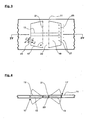
- a section of a band-shaped flexible sheet 11 is shown.
- the latter may be made of silicone or other flexible plastic material, rubber or a laminate of any of the foregoing with a backing or reinforcing material 15 such as plastic or steel filaments.
- the plastic or metal threads have elastic properties. They may be introduced in the form of a fabric or as fibers lying parallel or only in the form of individual, exactly arranged metal strips 13. Nano- or microstructured substances 41 or magnetic elements 27 may also be introduced into the fabric 11.
- slots 11 are provided by a punching or by cutting with a knife or an energy beam (laser or water jet) or by Trennlageneinbau during casting through which 11 flaps or flaps 19 arise in the fabric. These flaps 19 are still connected to the surrounding sheet 11 along a substantially vertical bending line 21.
- the bending lines 21 can be purely imaginary lines (see dash-dotted lines Line in FIG. 3 ) or it can - if it is the sheet 11 is a slightly more rigid material - along the bending lines 21 notches or grooves 23 or short cuts may be formed.
- the flaps 19 are trapezoidal and along their longest edge (base) extend the bending lines 21.
- the two short edges meet at an acute angle alpha with the bending line 21. This ensures that water droplets on condensing on the sheet 11th along the sloping slot 17,25 can flow down and not stick within the slot and can freeze there.
- FIG. 11 Other possible shapes, such as triangles, semicircles etc. for the cut-out flaps, which have comparable properties, are disclosed in US Pat FIG. 11 shown.
- FIG. 3 is further seen that along the vertically extending slots 25 magnetic elements 27 are incorporated into the sheet 11 and by their mutual attraction keep the flaps 19 (+) in the rest position in the plane of the surrounding sheet 11 (-), if not from the one or the other side a force on the flaps 19 is exercised.
- FIG. 4 is shown schematically as the flaps 19 are swung out of the plane of the sheet 11 on both sides.
- FIG. 3 only a section of the band-shaped fabric is shown. It can be in this at predetermined intervals each one or, connected by a central web 29 or with a bending line 21, two flaps 19 or more pairs of flaps be inserted.
- FIG. 5 is a horizontal section along line IV-IV in FIG. 3 represented by two closure flaps 19, on the one hand rests on support profiles 31 and on the other hand rests on a support grid 33.
- the latter prevents the swinging of the flaps 19 in the direction of the support grid 33.
- the air can escape only in the direction of arrow 9 (one-way closure).
- FIGS. 6, 7 and 8th showing horizontal sections through sheets 11, the arrangement of the flaps 19 can be seen.
- the closure flaps 19 are always arranged between two support profiles 31, so that the fabric 11 is in this area on the one hand flat and on the other hand kept taut. It is possible for one support post 31 to be within and one adjacent to outside a polygon-shaped sheet ( FIGS. 7 and 8th ).
- FIG. 6 further an arrangement of the support posts 31 'is shown, which within the fabric 11th lie, ie either glued, extruded or laminated.
- FIGS. 9 and 10 is a further embodiment of the arrangement of the closure flaps 19 can be seen.
- a device for retaining rising hot air in a, for example round tube 35 six support posts 31 are arranged and on the outer edges of the fabric 11 is stretched. This is designed so that in each case between two support posts 31, a flap pair 19 comes to rest.
- the theoretical opening areas of the flap pairs 19 are shown in fine semi-circular lines.
- This ready-to-use module can be used vertically with suitable means chosen in a vapor or exhaust pipe 1.
- the holding means for the insert module are not shown for the sake of clarity.
- FIG. 11 Design variants of the flaps 19 are shown. Not shown is a paired, parallel arrangement of two flaps 19 with a common bending line 21st
- FIG. 12 shows in horizontal section a further fastening of the sheet 11 on the support profile 31 by means of a bolted fastener 43rd
- FIG. 13 shows a further variant of the attachment of the sheet 11 by Anspritzitati 45 on the support profile 31st
- Suitable reinforcing agents are fabrics, strip-shaped inserts or films of individual fibers or strips of suitable plastic or metal, which materials have self-restoring properties.
- the fabrics 11 with the closure flaps 19 can be made of hydrophobic material or can be rendered hydrophobic or superhydrophobic by coating, adding substances or surface treatment.
Landscapes
- Engineering & Computer Science (AREA)
- Chemical & Material Sciences (AREA)
- Combustion & Propulsion (AREA)
- Mechanical Engineering (AREA)
- General Engineering & Computer Science (AREA)
- Physics & Mathematics (AREA)
- Fluid Mechanics (AREA)
- Tents Or Canopies (AREA)
- Air-Flow Control Members (AREA)
Priority Applications (1)
| Application Number | Priority Date | Filing Date | Title |
|---|---|---|---|
| PL09405170T PL2175207T3 (pl) | 2008-10-10 | 2009-10-01 | Urządzenie odcinające przepływ wznoszącego się, ciepłego powietrza, montowane w pionie na rurach, przewodach elastycznych lub kanałach |
Applications Claiming Priority (1)
| Application Number | Priority Date | Filing Date | Title |
|---|---|---|---|
| CH01613/08A CH699655A1 (de) | 2008-10-10 | 2008-10-10 | Vorrichtung zum Zurückhalten aufsteigender Warmluft. |
Publications (2)
| Publication Number | Publication Date |
|---|---|
| EP2175207A1 EP2175207A1 (de) | 2010-04-14 |
| EP2175207B1 true EP2175207B1 (de) | 2015-03-04 |
Family
ID=41509799
Family Applications (1)
| Application Number | Title | Priority Date | Filing Date |
|---|---|---|---|
| EP09405170.3A Active EP2175207B1 (de) | 2008-10-10 | 2009-10-01 | Auf Rohre, Schläuche oder Kanäle vertikal montierbare Vorrichtung zum Zurückhalten aufsteigender Warmluft |
Country Status (4)
| Country | Link |
|---|---|
| EP (1) | EP2175207B1 (da) |
| CH (1) | CH699655A1 (da) |
| DK (1) | DK2175207T3 (da) |
| PL (1) | PL2175207T3 (da) |
Families Citing this family (2)
| Publication number | Priority date | Publication date | Assignee | Title |
|---|---|---|---|---|
| CH703714A2 (de) * | 2010-08-30 | 2012-03-15 | Oekag Wassertechnik Schweiz Ag | Auf Dachwasserabläufe aufsetzbare Vorrichtung zum Zurückhalten von aufsteigender Luft und Ableiten von Dachwasser. |
| US9157652B2 (en) | 2012-08-30 | 2015-10-13 | Ronald Hugh Chamness | Vent cover with biased door |
Family Cites Families (11)
| Publication number | Priority date | Publication date | Assignee | Title |
|---|---|---|---|---|
| GB1111261A (en) * | 1965-03-24 | 1968-04-24 | A I R Air Conditioning And Ref | Improvements in ventilating systems |
| CH476502A (de) * | 1965-04-02 | 1969-08-15 | Luwa Ag | Verschlussvorrichtung zum Verschliessen von Belüftungsleitungen von Schutzbauten |
| US4416415A (en) | 1981-10-20 | 1983-11-22 | Leonard W. Suroff | Automatic damper assembly |
| EP0568946A1 (en) | 1992-05-08 | 1993-11-10 | Takeda Chemical Industries, Ltd. | Compound TAN-1607A, its derivatives, their production, and use thereof |
| DK4194A (da) | 1994-01-10 | 1995-07-11 | Villadsens Fab As Jens | Tagopbygning |
| IT1270028B (it) * | 1994-03-09 | 1997-04-28 | Leonelli Paolo | Conduttura con bocchette di erogazione del fluido trasportato, particolarmente per impianti per il condizionamento di ambienti civilio industriali |
| DE19510502C1 (de) * | 1995-03-23 | 1996-07-11 | Ernest P Sukup | Geruchverschluß für ein Abwasserrohr |
| US6149516A (en) | 1999-07-09 | 2000-11-21 | Canplas Industries, Ltd. | Soffit vent apparatus |
| US6318397B1 (en) * | 1999-08-04 | 2001-11-20 | Donald G. Huber | Side port floor drain |
| EP1568946A1 (de) * | 2004-02-26 | 2005-08-31 | Oekag Wassertechnik (Schweiz) AG | Vorrichtung zum Zurückhalten aufsteigender Warmluft |
| US7766044B2 (en) * | 2005-10-24 | 2010-08-03 | Val-Matic Valve & Manufacturing Corp. | Two-way damper |
-
2008
- 2008-10-10 CH CH01613/08A patent/CH699655A1/de not_active Application Discontinuation
-
2009
- 2009-10-01 DK DK09405170.3T patent/DK2175207T3/da active
- 2009-10-01 EP EP09405170.3A patent/EP2175207B1/de active Active
- 2009-10-01 PL PL09405170T patent/PL2175207T3/pl unknown
Also Published As
| Publication number | Publication date |
|---|---|
| PL2175207T3 (pl) | 2015-08-31 |
| CH699655A1 (de) | 2010-04-15 |
| EP2175207A1 (de) | 2010-04-14 |
| DK2175207T3 (da) | 2015-06-15 |
Similar Documents
| Publication | Publication Date | Title |
|---|---|---|
| CN101778980A (zh) | 具有供气通道的天窗 | |
| EP2594725A2 (de) | Fenster | |
| WO2020125017A1 (zh) | 水平百叶排烟窗 | |
| DE102008020941B4 (de) | Luftführungselement zum Zuführen und/oder Abführen von Luft | |
| EP2175207A1 (de) | Auf Rohre, Schläuche oder Kanäle vertikal montierbare Vorrichtung zum Zurückhalten aufsteigender Warmluft | |
| DE19723485C2 (de) | Vorrichtung zum Be- und Entlüften von Räumen | |
| EP1624258A2 (de) | Einrichtung zur Raumlüftung und Einbaumodul zur Raumlüftung | |
| DE102012002109A1 (de) | Flächenlüfter | |
| DE102016103950B4 (de) | Anordnung zur Be- und Entlüftung von Räumen im Bereich eines Fensters | |
| EP0951630A1 (de) | Raumbelüftungsverfahren | |
| DE69728562T2 (de) | Dränagerinne | |
| AT505746B1 (de) | Brandschutzanlage für gebäude | |
| EP2636812A1 (de) | Verfahren und Vorrichtung zur Dachentwässerung in Form einer Hauptentwässerung und einer Notentwässerung | |
| EP1568946A1 (de) | Vorrichtung zum Zurückhalten aufsteigender Warmluft | |
| EP2423407B1 (de) | Auf Dachwasserabläufe aufsetzbare Vorrichtung zum Zurückhalten von aufsteigender Luft und Ableiten von Dachwasser | |
| EP2631553B1 (de) | Zuluftventil | |
| EP2048318A2 (en) | Ventilation device | |
| DE3313875A1 (de) | Hohles first- oder gratabdeckelement mit lueftungsoeffnungen | |
| EP2423398A1 (de) | Vorrichtung zur Innenisolation einer Bauteilwand | |
| KR102391884B1 (ko) | 빗물유입방지 기능과 우수한 통기 성능을 갖는 스마트 방충망 | |
| JPS5822835A (ja) | 原子力設備建屋空気取入口のル−バ装置 | |
| DE10352113A1 (de) | Wetterschutzgitter | |
| DE3900031C1 (en) | Weather protection grating for a rear-ventilation gap | |
| AT502484A4 (de) | Dachplatte mit traufenseitigem plastischen streifen | |
| DE102024127253A1 (de) | Belüftungsprofil zum aktiven Belüften und/oder Entlüften einer Bauwerksabdichtung, Bauwerksabdichtung sowie Verfahren zum aktiven Belüften und/oder Entlüften einer Bauwerksabdichtung |
Legal Events
| Date | Code | Title | Description |
|---|---|---|---|
| PUAI | Public reference made under article 153(3) epc to a published international application that has entered the european phase |
Free format text: ORIGINAL CODE: 0009012 |
|
| AK | Designated contracting states |
Kind code of ref document: A1 Designated state(s): AT BE BG CH CY CZ DE DK EE ES FI FR GB GR HR HU IE IS IT LI LT LU LV MC MK MT NL NO PL PT RO SE SI SK SM TR |
|
| AX | Request for extension of the european patent |
Extension state: AL BA RS |
|
| 17P | Request for examination filed |
Effective date: 20100924 |
|
| RIC1 | Information provided on ipc code assigned before grant |
Ipc: F24F 7/02 20060101AFI20140730BHEP Ipc: F24F 13/10 20060101ALI20140730BHEP Ipc: F24F 11/04 20060101ALI20140730BHEP Ipc: E04D 13/17 20060101ALI20140730BHEP |
|
| GRAP | Despatch of communication of intention to grant a patent |
Free format text: ORIGINAL CODE: EPIDOSNIGR1 |
|
| INTG | Intention to grant announced |
Effective date: 20141001 |
|
| GRAS | Grant fee paid |
Free format text: ORIGINAL CODE: EPIDOSNIGR3 |
|
| GRAA | (expected) grant |
Free format text: ORIGINAL CODE: 0009210 |
|
| AK | Designated contracting states |
Kind code of ref document: B1 Designated state(s): AT BE BG CH CY CZ DE DK EE ES FI FR GB GR HR HU IE IS IT LI LT LU LV MC MK MT NL NO PL PT RO SE SI SK SM TR |
|
| REG | Reference to a national code |
Ref country code: GB Ref legal event code: FG4D Free format text: NOT ENGLISH |
|
| REG | Reference to a national code |
Ref country code: CH Ref legal event code: EP |
|
| REG | Reference to a national code |
Ref country code: IE Ref legal event code: FG4D Free format text: LANGUAGE OF EP DOCUMENT: GERMAN |
|
| REG | Reference to a national code |
Ref country code: AT Ref legal event code: REF Ref document number: 714234 Country of ref document: AT Kind code of ref document: T Effective date: 20150415 |
|
| REG | Reference to a national code |
Ref country code: DE Ref legal event code: R096 Ref document number: 502009010707 Country of ref document: DE Effective date: 20150416 |
|
| REG | Reference to a national code |
Ref country code: CH Ref legal event code: NV Representative=s name: HANS RUDOLF GACHNANG PATENTANWALT, CH |
|
| REG | Reference to a national code |
Ref country code: DK Ref legal event code: T3 Effective date: 20150608 |
|
| REG | Reference to a national code |
Ref country code: SE Ref legal event code: TRGR |
|
| REG | Reference to a national code |
Ref country code: NL Ref legal event code: T3 |
|
| REG | Reference to a national code |
Ref country code: NO Ref legal event code: T2 Effective date: 20150304 |
|
| PG25 | Lapsed in a contracting state [announced via postgrant information from national office to epo] |
Ref country code: FI Free format text: LAPSE BECAUSE OF FAILURE TO SUBMIT A TRANSLATION OF THE DESCRIPTION OR TO PAY THE FEE WITHIN THE PRESCRIBED TIME-LIMIT Effective date: 20150304 Ref country code: HR Free format text: LAPSE BECAUSE OF FAILURE TO SUBMIT A TRANSLATION OF THE DESCRIPTION OR TO PAY THE FEE WITHIN THE PRESCRIBED TIME-LIMIT Effective date: 20150304 Ref country code: LT Free format text: LAPSE BECAUSE OF FAILURE TO SUBMIT A TRANSLATION OF THE DESCRIPTION OR TO PAY THE FEE WITHIN THE PRESCRIBED TIME-LIMIT Effective date: 20150304 Ref country code: ES Free format text: LAPSE BECAUSE OF FAILURE TO SUBMIT A TRANSLATION OF THE DESCRIPTION OR TO PAY THE FEE WITHIN THE PRESCRIBED TIME-LIMIT Effective date: 20150304 |
|
| REG | Reference to a national code |
Ref country code: LT Ref legal event code: MG4D |
|
| PG25 | Lapsed in a contracting state [announced via postgrant information from national office to epo] |
Ref country code: LV Free format text: LAPSE BECAUSE OF FAILURE TO SUBMIT A TRANSLATION OF THE DESCRIPTION OR TO PAY THE FEE WITHIN THE PRESCRIBED TIME-LIMIT Effective date: 20150304 Ref country code: GR Free format text: LAPSE BECAUSE OF FAILURE TO SUBMIT A TRANSLATION OF THE DESCRIPTION OR TO PAY THE FEE WITHIN THE PRESCRIBED TIME-LIMIT Effective date: 20150605 |
|
| REG | Reference to a national code |
Ref country code: PL Ref legal event code: T3 |
|
| REG | Reference to a national code |
Ref country code: FR Ref legal event code: PLFP Year of fee payment: 7 |
|
| PG25 | Lapsed in a contracting state [announced via postgrant information from national office to epo] |
Ref country code: RO Free format text: LAPSE BECAUSE OF FAILURE TO SUBMIT A TRANSLATION OF THE DESCRIPTION OR TO PAY THE FEE WITHIN THE PRESCRIBED TIME-LIMIT Effective date: 20150304 Ref country code: SK Free format text: LAPSE BECAUSE OF FAILURE TO SUBMIT A TRANSLATION OF THE DESCRIPTION OR TO PAY THE FEE WITHIN THE PRESCRIBED TIME-LIMIT Effective date: 20150304 Ref country code: CZ Free format text: LAPSE BECAUSE OF FAILURE TO SUBMIT A TRANSLATION OF THE DESCRIPTION OR TO PAY THE FEE WITHIN THE PRESCRIBED TIME-LIMIT Effective date: 20150304 Ref country code: PT Free format text: LAPSE BECAUSE OF FAILURE TO SUBMIT A TRANSLATION OF THE DESCRIPTION OR TO PAY THE FEE WITHIN THE PRESCRIBED TIME-LIMIT Effective date: 20150706 Ref country code: EE Free format text: LAPSE BECAUSE OF FAILURE TO SUBMIT A TRANSLATION OF THE DESCRIPTION OR TO PAY THE FEE WITHIN THE PRESCRIBED TIME-LIMIT Effective date: 20150304 |
|
| PG25 | Lapsed in a contracting state [announced via postgrant information from national office to epo] |
Ref country code: IS Free format text: LAPSE BECAUSE OF FAILURE TO SUBMIT A TRANSLATION OF THE DESCRIPTION OR TO PAY THE FEE WITHIN THE PRESCRIBED TIME-LIMIT Effective date: 20150704 |
|
| REG | Reference to a national code |
Ref country code: DE Ref legal event code: R097 Ref document number: 502009010707 Country of ref document: DE |
|
| PG25 | Lapsed in a contracting state [announced via postgrant information from national office to epo] |
Ref country code: IT Free format text: LAPSE BECAUSE OF FAILURE TO SUBMIT A TRANSLATION OF THE DESCRIPTION OR TO PAY THE FEE WITHIN THE PRESCRIBED TIME-LIMIT Effective date: 20150304 |
|
| PLBE | No opposition filed within time limit |
Free format text: ORIGINAL CODE: 0009261 |
|
| STAA | Information on the status of an ep patent application or granted ep patent |
Free format text: STATUS: NO OPPOSITION FILED WITHIN TIME LIMIT |
|
| 26N | No opposition filed |
Effective date: 20151207 |
|
| PG25 | Lapsed in a contracting state [announced via postgrant information from national office to epo] |
Ref country code: SI Free format text: LAPSE BECAUSE OF FAILURE TO SUBMIT A TRANSLATION OF THE DESCRIPTION OR TO PAY THE FEE WITHIN THE PRESCRIBED TIME-LIMIT Effective date: 20150304 |
|
| PG25 | Lapsed in a contracting state [announced via postgrant information from national office to epo] |
Ref country code: LU Free format text: LAPSE BECAUSE OF FAILURE TO SUBMIT A TRANSLATION OF THE DESCRIPTION OR TO PAY THE FEE WITHIN THE PRESCRIBED TIME-LIMIT Effective date: 20151001 |
|
| PG25 | Lapsed in a contracting state [announced via postgrant information from national office to epo] |
Ref country code: MC Free format text: LAPSE BECAUSE OF FAILURE TO SUBMIT A TRANSLATION OF THE DESCRIPTION OR TO PAY THE FEE WITHIN THE PRESCRIBED TIME-LIMIT Effective date: 20150304 |
|
| REG | Reference to a national code |
Ref country code: IE Ref legal event code: MM4A |
|
| REG | Reference to a national code |
Ref country code: FR Ref legal event code: PLFP Year of fee payment: 8 |
|
| PG25 | Lapsed in a contracting state [announced via postgrant information from national office to epo] |
Ref country code: IE Free format text: LAPSE BECAUSE OF NON-PAYMENT OF DUE FEES Effective date: 20151001 |
|
| PG25 | Lapsed in a contracting state [announced via postgrant information from national office to epo] |
Ref country code: HU Free format text: LAPSE BECAUSE OF FAILURE TO SUBMIT A TRANSLATION OF THE DESCRIPTION OR TO PAY THE FEE WITHIN THE PRESCRIBED TIME-LIMIT; INVALID AB INITIO Effective date: 20091001 Ref country code: BG Free format text: LAPSE BECAUSE OF FAILURE TO SUBMIT A TRANSLATION OF THE DESCRIPTION OR TO PAY THE FEE WITHIN THE PRESCRIBED TIME-LIMIT Effective date: 20150304 Ref country code: SM Free format text: LAPSE BECAUSE OF FAILURE TO SUBMIT A TRANSLATION OF THE DESCRIPTION OR TO PAY THE FEE WITHIN THE PRESCRIBED TIME-LIMIT Effective date: 20150304 |
|
| PG25 | Lapsed in a contracting state [announced via postgrant information from national office to epo] |
Ref country code: CY Free format text: LAPSE BECAUSE OF FAILURE TO SUBMIT A TRANSLATION OF THE DESCRIPTION OR TO PAY THE FEE WITHIN THE PRESCRIBED TIME-LIMIT Effective date: 20150304 |
|
| PG25 | Lapsed in a contracting state [announced via postgrant information from national office to epo] |
Ref country code: TR Free format text: LAPSE BECAUSE OF FAILURE TO SUBMIT A TRANSLATION OF THE DESCRIPTION OR TO PAY THE FEE WITHIN THE PRESCRIBED TIME-LIMIT Effective date: 20150304 Ref country code: MT Free format text: LAPSE BECAUSE OF FAILURE TO SUBMIT A TRANSLATION OF THE DESCRIPTION OR TO PAY THE FEE WITHIN THE PRESCRIBED TIME-LIMIT Effective date: 20150304 |
|
| REG | Reference to a national code |
Ref country code: FR Ref legal event code: PLFP Year of fee payment: 9 |
|
| PG25 | Lapsed in a contracting state [announced via postgrant information from national office to epo] |
Ref country code: MK Free format text: LAPSE BECAUSE OF FAILURE TO SUBMIT A TRANSLATION OF THE DESCRIPTION OR TO PAY THE FEE WITHIN THE PRESCRIBED TIME-LIMIT Effective date: 20150304 |
|
| REG | Reference to a national code |
Ref country code: FR Ref legal event code: PLFP Year of fee payment: 10 |
|
| REG | Reference to a national code |
Ref country code: DE Ref legal event code: R082 Ref document number: 502009010707 Country of ref document: DE Representative=s name: KANDLBINDER, MARKUS, DIPL.-PHYS., DE |
|
| REG | Reference to a national code |
Ref country code: CH Ref legal event code: U11 Free format text: ST27 STATUS EVENT CODE: U-0-0-U10-U11 (AS PROVIDED BY THE NATIONAL OFFICE) Effective date: 20251101 |
|
| PGFP | Annual fee paid to national office [announced via postgrant information from national office to epo] |
Ref country code: NL Payment date: 20251023 Year of fee payment: 17 |
|
| PGFP | Annual fee paid to national office [announced via postgrant information from national office to epo] |
Ref country code: DE Payment date: 20251020 Year of fee payment: 17 |
|
| PGFP | Annual fee paid to national office [announced via postgrant information from national office to epo] |
Ref country code: GB Payment date: 20251024 Year of fee payment: 17 |
|
| PGFP | Annual fee paid to national office [announced via postgrant information from national office to epo] |
Ref country code: NO Payment date: 20251022 Year of fee payment: 17 |
|
| PGFP | Annual fee paid to national office [announced via postgrant information from national office to epo] |
Ref country code: AT Payment date: 20251021 Year of fee payment: 17 |
|
| PGFP | Annual fee paid to national office [announced via postgrant information from national office to epo] |
Ref country code: DK Payment date: 20251023 Year of fee payment: 17 |
|
| PGFP | Annual fee paid to national office [announced via postgrant information from national office to epo] |
Ref country code: FR Payment date: 20251024 Year of fee payment: 17 |
|
| PGFP | Annual fee paid to national office [announced via postgrant information from national office to epo] |
Ref country code: BE Payment date: 20251022 Year of fee payment: 17 |
|
| PGFP | Annual fee paid to national office [announced via postgrant information from national office to epo] |
Ref country code: CH Payment date: 20251101 Year of fee payment: 17 Ref country code: SE Payment date: 20251023 Year of fee payment: 17 |
|
| PGFP | Annual fee paid to national office [announced via postgrant information from national office to epo] |
Ref country code: PL Payment date: 20251017 Year of fee payment: 17 |