EP2175284B1 - Beschleunigungssensor mit Kraftrückkopplung als mikroelektromechanisches System (MEMS) - Google Patents
Beschleunigungssensor mit Kraftrückkopplung als mikroelektromechanisches System (MEMS) Download PDFInfo
- Publication number
- EP2175284B1 EP2175284B1 EP09172009.4A EP09172009A EP2175284B1 EP 2175284 B1 EP2175284 B1 EP 2175284B1 EP 09172009 A EP09172009 A EP 09172009A EP 2175284 B1 EP2175284 B1 EP 2175284B1
- Authority
- EP
- European Patent Office
- Prior art keywords
- proof mass
- pole piece
- magnet
- mems accelerometer
- housing
- Prior art date
- Legal status (The legal status is an assumption and is not a legal conclusion. Google has not performed a legal analysis and makes no representation as to the accuracy of the status listed.)
- Not-in-force
Links
- 230000004907 flux Effects 0.000 claims description 13
- 238000000034 method Methods 0.000 claims description 5
- 239000005388 borosilicate glass Substances 0.000 claims description 2
- 238000010586 diagram Methods 0.000 description 7
- 229910052710 silicon Inorganic materials 0.000 description 3
- 239000010703 silicon Substances 0.000 description 3
- 239000000463 material Substances 0.000 description 2
- 229910000967 As alloy Inorganic materials 0.000 description 1
- 229910001374 Invar Inorganic materials 0.000 description 1
- 230000001133 acceleration Effects 0.000 description 1
- 230000000694 effects Effects 0.000 description 1
- 238000010438 heat treatment Methods 0.000 description 1
- 239000011810 insulating material Substances 0.000 description 1
- 229910001004 magnetic alloy Inorganic materials 0.000 description 1
- 230000035945 sensitivity Effects 0.000 description 1
- 239000007787 solid Substances 0.000 description 1
- 239000010935 stainless steel Substances 0.000 description 1
- 229910001220 stainless steel Inorganic materials 0.000 description 1
Images


Classifications
-
- G—PHYSICS
- G01—MEASURING; TESTING
- G01P—MEASURING LINEAR OR ANGULAR SPEED, ACCELERATION, DECELERATION, OR SHOCK; INDICATING PRESENCE, ABSENCE, OR DIRECTION, OF MOVEMENT
- G01P15/00—Measuring acceleration; Measuring deceleration; Measuring shock, i.e. sudden change of acceleration
- G01P15/02—Measuring acceleration; Measuring deceleration; Measuring shock, i.e. sudden change of acceleration by making use of inertia forces using solid seismic masses
- G01P15/08—Measuring acceleration; Measuring deceleration; Measuring shock, i.e. sudden change of acceleration by making use of inertia forces using solid seismic masses with conversion into electric or magnetic values
- G01P15/13—Measuring acceleration; Measuring deceleration; Measuring shock, i.e. sudden change of acceleration by making use of inertia forces using solid seismic masses with conversion into electric or magnetic values by measuring the force required to restore a proofmass subjected to inertial forces to a null position
- G01P15/132—Measuring acceleration; Measuring deceleration; Measuring shock, i.e. sudden change of acceleration by making use of inertia forces using solid seismic masses with conversion into electric or magnetic values by measuring the force required to restore a proofmass subjected to inertial forces to a null position with electromagnetic counterbalancing means
Definitions
- Typical configurations for force balance Micro Electro-Mechanical Systems (MEMS) accelerometers that have a proof mass with a coil have a magnetic circuit configuration with a large reluctance value.
- previous coil and magnetic circuit configurations are structured such that a magnetic field runs parallel with the plane of a spiral coil. The magnetic field excites a return path that penetrates a proof mass using holes. A gap in the magnetic return path with this configuration is defined by a diameter of the coil, and is thus relatively large with a corresponding large reluctance of the magnetic circuit which results in a high scale factor.
- This type of coil configuration requires a level of current to servo the accelerometer that generates heating effects that create nonlinearities which degrade performance.
- the present invention is a system a Micro Electro-Mechanical Systems (MEMS) accelerometer and acceleration sensing methods having improved sensitivity, a greater signal to noise ratio, and lower power requirements.
- An example MEMS accelerometer includes a proof mass suspended by at least one flexure, a planar coil on the proof mass, at least one magnet, a first pole piece positioned proximate a first side of the proof mass, and a second pole piece positioned proximate a second side of the proof mass.
- a magnetic flux field passes from at least one of the at least one magnets, through the first pole piece, through the planar coil at a flux angle between approximately 30 degrees and approximately 60 degrees relative to the coil plane, and into the second pole piece. In an example embodiment, the flux angle is approximately 45 degrees.
- a method includes sensing a capacitance of a pickoff in the MEMS accelerometer and rebalancing the MEMS accelerometer by sending a current through the planar coil.
- the at least one magnet includes a first magnet adjacent to the first pole piece and a second magnet adjacent to the second pole piece.
- the first magnet has an annular shape.
- the MEMS accelerometer further includes a first housing layer positioned on a first side of the proof mass and a second housing layer positioned on a second side of the proof mass.
- the first housing layer defines a first recessed area and the second housing layer defines a second recessed area.
- the first pole piece extends at least partially into the first recessed area and the second pole piece extends at least partially into the second recessed area.
- the first and second recessed areas allow the first and second pole pieces to have a smaller gap between them, which results in a lower reluctance for a magnetic circuit that passes through the coil on the proof mass.
- a method includes sensing a capacitance of a pickoff in the MEMS accelerometer and rebalancing the MEMS accelerometer by sending a current based on the sensed capacitance through the planar coil.
- FIGURE 1 is a block diagram of a Micro Electro-Mechanical Systems (MEMS) accelerometer system 20 formed in accordance with an embodiment of the invention.
- the MEMS accelerometer system 20 includes an accelerometer 22 and a control unit 24.
- the control unit 24 includes a sense electronics component 26 and a drive electronics component 28, both in signal communication with the MEMS accelerometer 22.
- the control unit 24 also includes a controller 30 in signal communication with the sense electronics component 26 and the drive electronics component 28.
- the accelerometer 22 includes a proof mass suspended by at least one flexure within a housing and a magnetic rebalancing component for rebalancing the proof mass about the at least one flexure.
- the magnetic rebalancing component includes at least one magnet, at least one pole piece, and a magnetic return path structure.
- the magnetic rebalancing component servo actuates the accelerometer 22 by passing a current through at least one planar coil located on the proof mass that lies within a magnetic flux field that passes at an angle between approximately 30 degrees and approximately 60 degrees relative to the coil plane through the at least one planar coil.
- the magnetic flux field includes a component in the plane of the coil and a component normal to the plane of the coil. The component of the magnetic flux field in the plane of the coil is used to servo actuate the proof mass.
- a magnetic shield may be present around the accelerometer 22 and/or the accelerometer system 20 in some embodiments for use in a multi-sensor environment. Additional detail for example embodiments of the accelerometer 22 is discussed with respect to FIGURE 2 .
- FIGURE 2 is a diagram of a perspective view of a quarter section of a MEMS accelerometer 40 formed in accordance with an example embodiment of the invention.
- the accelerometer 40 is an example of the accelerometer 22 shown in FIGURE 1 .
- the accelerometer 40 includes a magnetic return path housing structure 42.
- the magnetic return path housing structure 42 includes a first piece 44 and a second piece 46.
- the magnetic return path housing structure 42 may be formed of a magnetic alloy with a thermal expansion coefficient similar to silicon.
- the magnetic return path housing structure 42 may be formed of invar 39, for example.
- a first end of a first magnet 48 is attached to an inner surface of the first piece 44 of the magnetic return path housing structure 42 and a first end of a second magnet 50 is attached to an inner surface of the second piece 46 of the magnetic return path housing structure 42.
- a first pole piece 52 is attached to a second end of the first magnet 48 and a second pole piece 54 is attached to a second end of the second magnet 50.
- the first and second pole pieces 52, 54 are formed of a magnetically permeable material such as 430F or 430FR stainless steel.
- the first and second pole pieces 52, 54 may also be formed of a material such as alloy 39 that has a coefficient of thermal expansion (CTE) relatively close to the CTE of silicon to provide additional stability over a range of temperature variation.
- a device stack 60 is positioned between the first pole piece 52 and the second pole piece 54.
- FIGURE 3 is a diagram of a cross-sectional side view of the MEMS accelerometer 40 showing additional detail for the device stack 60 shown in FIGURE 2 .
- FIGURE 3 is not shown with the same relative scale for various components as FIGURE 2 for clarity.
- the device stack 60 includes a first housing layer 62 and a second housing layer 64 that may be formed of an insulating material such as borosilicate glass in an example embodiment.
- a device layer 66 is positioned between the first and second housing layers 62, 64.
- the device layer 66 includes a proof mass 68 that is suspended in an outer ring 69 within the first and second housing layers 62, 64 by at least one flexure 70.
- the flexure 70 is a hinge type flexure and the proof mass is formed of silicon.
- a spiral planar coil 72 is located on a first side of the proof mass 68.
- the coil 72 is formed of metalized traces in an example embodiment, but may also be formed in a different manner.
- each of the coils 72 has approximately 10 turns that is approximately 45 microns wide with a spacing between turns of approximately 15 microns and a thickness of approximately 0.5 microns.
- other coil configurations such as oval or rectangular spirals may be used and different numbers of turns and dimensions may be used in some embodiments.
- a second coil on the second side of the proof mass may also be present.
- the first and second pole pieces 52, 54 are positioned such that a magnetic flux angle 73 of approximately 45 degrees is present relative to the plane of the coil 72. Although a cross-section of the magnetic flux field may have some curvature, the flux field is preferably approximately linear through the plane of the coils 72.
- a first pickoff 74 is positioned on the first side of the proof mass 68 and a second pickoff 76 is positioned on a second side of the proof mass 68.
- the first housing layer 62 defines a first recessed area 78 and the second housing layer defines a second recessed area 80.
- the first pole piece 52 includes a face 53 proximate the first side of the proof mass 68 that is positioned partially within the first recessed area 78 and the second pole piece 54 includes a face 55 positioned proximate the second side of the proof mass 68 that is positioned partially within the second recessed area 80.
- the first and second magnets 48, 50 are charged in an orientation normal to the plane of the proof mass 68.
- This charging orientation results in a north pole of the first magnet 48 being in contact with the first pole piece 52 and a south pole of the first magnet 48 being in contact with the magnetic return path housing structure 42.
- Other charging orientations may be used in other embodiments.
- the first magnet 48 is shown as an annular magnet. However, other shapes may be used, or a plurality of magnets rather than a single magnet in contact with the first pole piece 52.
- the second magnet 50 is shown as a solid closed cylinder in FIGURES 2 and 3 . However, other shapes, such as an annular shape may be used.
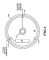
- FIGURE 4 is a top view of a proof mass 168 formed in accordance with an embodiment of the invention.
- the proof mass 168 is suspended in an outer ring 169 by a plurality of flexures 170.
- a spiral planar coil 172 is located on the proof mass 168.
- a plate 176 of a pickoff is also located on the proof mass 168.
- the proof mass 168 corresponds to the proof mass 68
- one of the flexures 170 corresponds to the flexure 70
- the coil 172 corresponds to the coil 72
- the plate 176 corresponds to a portion of the pickoff 76 shown in FIGURE 3 .
- the coil 172 may be in signal communication with the drive electronics component 28 and the plate 176 may be in signal communication with the sense electronics component 26 shown in FIGURE 1 in an example embodiment.
- An inner portion of the coil 172 may also include a connection (not shown) to the drive electronics component 28.
- the second magnet 50 may not be present in some embodiments, with the second pole piece 54 being directly connected to the magnetic path return structure 42. Additional magnets or different magnet and pole piece configurations may also be used in some embodiments. The invention should be determined entirely by reference to the claims that follow.
Landscapes
- Physics & Mathematics (AREA)
- Electromagnetism (AREA)
- General Physics & Mathematics (AREA)
- Micromachines (AREA)
Claims (10)
- Mikroelektromechanisches Beschleunigungssensor-System (MEMS-Beschleunigungssensor) (40), das Folgendes umfasst:ein Gehäuse (44);eine Prüfmasse (68), die innerhalb des Gehäuses durch mindestens eine Biegung aufgehängt ist;mindestens eine ebene Spule (72), die sich auf der Prüfmasse befindet;mindestens einen Magneten (50);ein erstes Polstück (54) angrenzend an mindestens einen des mindestens einen Magneten;undein zweites Polstück (52),wobei mindestens eine Fläche des ersten Polstücks in der Nähe einer ersten Seite der Prüfmasse positioniert ist und mindestens eine Fläche des zweiten Polstücks in der Nähe einer zweiten Seite der Prüfmasse positioniert ist, so dass ein Magnetflussfeld von dem Magneten durch die Fläche des ersten Polstücks, durch die mindestens eine ebene Spule mit einem Flusswinkel zwischen ungefähr 30 Grad und ungefähr 60 Grad in Bezug auf die Spulenebene und in das zweite Polstück hindurchgeht.
- MEMS-Beschleunigungssensor nach Anspruch 1, wobei der mindestens eine Magnet Folgendes umfasst:einen ersten Magneten (50) angrenzend an das erste Polstück; undeinen zweiten Magneten (48) angrenzend an das zweite Polstück.
- MEMS-Beschleunigungssensor nach Anspruch 2, der ferner eine magnetische Rückleitungsstruktur umfasst, die an den ersten Magneten und den zweiten Magneten gekoppelt ist.
- MEMS-Beschleunigungssensor nach Anspruch 2, wobei der erste Magnet eine ringförmige Form besitzt.
- MEMS-Beschleunigungssensor nach Anspruch 1, wobei der Flusswinkel ungefähr 45 Grad beträgt.
- MEMS-Beschleunigungssensor nach Anspruch 1, wobei das Gehäuse eine erste Gehäuseschicht umfasst, die auf der ersten Seite der Prüfmasse positioniert ist, wobei die erste Gehäuseschicht einen ersten ausgesparten Bereich definiert, wobei sich mindestens eine der mindestens einen Fläche des ersten Polstücks, die in der Nähe der ersten Seite der Prüfmasse positioniert ist, zumindest teilweise in den ersten ausgesparten Bereich erstreckt.
- MEMS-Beschleunigungssensor nach Anspruch 6, wobei das Gehäuse ferner eine zweite Gehäuseschicht umfasst, die auf der zweiten Seite der Prüfmasse positioniert ist, wobei die zweite Gehäuseschicht einen zweiten ausgesparten Bereich definiert, wobei sich mindestens eine der mindestens einen Fläche des zweiten Polstücks, die in der Nähe der zweiten Seite der Prüfmasse positioniert ist, zumindest teilweise in den zweiten ausgesparten Bereich erstreckt.
- MEMS-Beschleunigungssensor nach Anspruch 7, wobei die erste und die zweite Gehäuseschicht aus Borsilikatglas bestehen.
- MEMS-Beschleunigungssensor nach Anspruch 1, wobei der Flusswinkel zwischen ungefähr 40 Grad und ungefähr 50 Grad liegt.
- Verfahren zum Betreiben eines MEMS-Beschleunigungssensors, wobei das Verfahren Folgendes umfasst:Erfassen einer Kapazität eines Aufnehmers in dem MEMS-Beschleunigungssensor;Anwenden eines ringförmigen Magnetfeldes über eine Prüfmasse, die durch Biegungen innerhalb eines Gehäuse aufgehängt ist, wobei das Magnetfeld einen Winkel zwischen 30 und 60 Grad in Bezug auf die Oberfläche der Prüfmasse besitzt; undErzeugen einer Kraft auf die Prüfmasse, indem ein Strom durch eine ebene Spule angelegt wird, die sich auf einer Seite der Prüfmasse befindet, wobei der Strom auf der erfassten Kapazität und dem Magnetfeldwert beruht,wobei das Erfassen einer Kapazität eines Aufnehmers in dem MEMS-Beschleunigungssensor umfasst, eine differenzielle Änderung der Kapazität eines ersten Aufnehmers und eines zweiten Aufnehmers zu erfassen.
Applications Claiming Priority (1)
| Application Number | Priority Date | Filing Date | Title |
|---|---|---|---|
| US12/247,512 US7997136B2 (en) | 2008-10-08 | 2008-10-08 | MEMS force balance accelerometer |
Publications (2)
| Publication Number | Publication Date |
|---|---|
| EP2175284A1 EP2175284A1 (de) | 2010-04-14 |
| EP2175284B1 true EP2175284B1 (de) | 2015-01-14 |
Family
ID=41429323
Family Applications (1)
| Application Number | Title | Priority Date | Filing Date |
|---|---|---|---|
| EP09172009.4A Not-in-force EP2175284B1 (de) | 2008-10-08 | 2009-10-01 | Beschleunigungssensor mit Kraftrückkopplung als mikroelektromechanisches System (MEMS) |
Country Status (3)
| Country | Link |
|---|---|
| US (1) | US7997136B2 (de) |
| EP (1) | EP2175284B1 (de) |
| JP (1) | JP5634697B2 (de) |
Families Citing this family (11)
| Publication number | Priority date | Publication date | Assignee | Title |
|---|---|---|---|---|
| US8065915B2 (en) * | 2008-10-08 | 2011-11-29 | Honeywell International Inc. | MEMS accelerometer |
| US8122767B2 (en) * | 2008-10-08 | 2012-02-28 | Honeywell International Inc. | D'arsonval movement mems accelerometer |
| US8215169B2 (en) * | 2009-03-26 | 2012-07-10 | Honeywell International Inc. | Using pole pieces to guide magnetic flux through a MEMS device and method of making |
| CN101893451B (zh) * | 2009-05-22 | 2013-08-21 | 鸿富锦精密工业(深圳)有限公司 | 电容式传感器及陀螺仪 |
| US20140290365A1 (en) * | 2013-04-02 | 2014-10-02 | Tao Ju | Mems device |
| CN102879077B (zh) * | 2012-09-18 | 2014-03-26 | 哈尔滨工程大学 | 一种同振式矢量水听器 |
| US10161956B2 (en) * | 2016-04-25 | 2018-12-25 | Honeywell International Inc. | Reducing bias in an accelerometer via a pole piece |
| US10816568B2 (en) | 2017-12-26 | 2020-10-27 | Physical Logic Ltd. | Closed loop accelerometer |
| DE102018222758A1 (de) * | 2018-12-21 | 2020-06-25 | Robert Bosch Gmbh | MEMS-Sensor mit einer Membran sowie Verfahren zur Herstellung eines MEMS-Sensors |
| CN110940328A (zh) * | 2019-12-13 | 2020-03-31 | 中北大学 | 一种基于平面线圈面内检测的微陀螺 |
| US11275098B2 (en) * | 2020-07-14 | 2022-03-15 | Honeywell International Inc. | Accelerometer including rectangular coil and rectangular pole piece |
Family Cites Families (22)
| Publication number | Priority date | Publication date | Assignee | Title |
|---|---|---|---|---|
| US4088027A (en) * | 1976-09-29 | 1978-05-09 | Hernandez E Norman | Force balance servo accelerometer |
| US4510802A (en) * | 1983-09-02 | 1985-04-16 | Sundstrand Data Control, Inc. | Angular rate sensor utilizing two vibrating accelerometers secured to a parallelogram linkage |
| JPS6054969U (ja) * | 1983-09-22 | 1985-04-17 | 横河電機株式会社 | サ−ボ加速度計 |
| US4726228A (en) * | 1986-04-16 | 1988-02-23 | Sundstrand Data Control, Inc. | Accelerometer proof mass interface |
| US4854169A (en) * | 1987-06-15 | 1989-08-08 | Japan Aviation Electronics Industry Ltd. | Accelerometer |
| FR2637984B1 (fr) | 1988-10-19 | 1991-01-11 | Sagem | Accelerometre pendulaire asservi a detection electrostatique |
| US4944184A (en) * | 1989-04-14 | 1990-07-31 | Sundstrand Data Control, Inc. | Asymmetric flexure for pendulous accelerometer |
| US5524488A (en) * | 1994-01-24 | 1996-06-11 | Alliedsignal Inc. | Flux control groove |
| FR2734641B1 (fr) * | 1995-05-24 | 1997-08-14 | Sextant Avionique | Accelerometre electromagnetique |
| US5731703A (en) * | 1995-10-31 | 1998-03-24 | The Charles Stark Draper Laboratory, Inc. | Micromechanical d'arsonval magnetometer |
| JP3818399B2 (ja) * | 1996-03-12 | 2006-09-06 | 株式会社ミツトヨ | 超小型加速度センサ |
| US5739431A (en) * | 1996-06-13 | 1998-04-14 | Alliedsignal, Inc. | Miniature magnetometer-accelerometer |
| JP2000028367A (ja) * | 1998-07-13 | 2000-01-28 | Wako:Kk | 角速度センサおよびこれを用いた角速度検出装置 |
| RU2155964C1 (ru) * | 1999-06-23 | 2000-09-10 | Коновалов Сергей Феодосьевич | Компенсационный маятниковый акселерометр |
| JP2002350459A (ja) * | 2001-05-23 | 2002-12-04 | Akashi Corp | 振動センサ、及び振動センサの製造方法 |
| US6664786B2 (en) * | 2001-07-30 | 2003-12-16 | Rockwell Automation Technologies, Inc. | Magnetic field sensor using microelectromechanical system |
| US6776042B2 (en) * | 2002-01-25 | 2004-08-17 | Kinemetrics, Inc. | Micro-machined accelerometer |
| US7346981B2 (en) * | 2002-08-07 | 2008-03-25 | Teledyne Licensing, Llc | Method for fabricating microelectromechanical system (MEMS) devices |
| US7191654B2 (en) * | 2005-08-17 | 2007-03-20 | Honeywell International Inc. | Methods and systems for adjusting magnetic return path with minimized reluctance |
| US7303935B2 (en) * | 2005-09-08 | 2007-12-04 | Teledyne Licensing, Llc | High temperature microelectromechanical (MEM) devices and fabrication method |
| US7347097B2 (en) * | 2006-03-01 | 2008-03-25 | Innalabs Technologies, Inc. | Servo compensating accelerometer |
| US8065915B2 (en) * | 2008-10-08 | 2011-11-29 | Honeywell International Inc. | MEMS accelerometer |
-
2008
- 2008-10-08 US US12/247,512 patent/US7997136B2/en active Active
-
2009
- 2009-10-01 EP EP09172009.4A patent/EP2175284B1/de not_active Not-in-force
- 2009-10-06 JP JP2009232419A patent/JP5634697B2/ja not_active Expired - Fee Related
Also Published As
| Publication number | Publication date |
|---|---|
| JP5634697B2 (ja) | 2014-12-03 |
| JP2010091565A (ja) | 2010-04-22 |
| US7997136B2 (en) | 2011-08-16 |
| US20100083759A1 (en) | 2010-04-08 |
| EP2175284A1 (de) | 2010-04-14 |
Similar Documents
| Publication | Publication Date | Title |
|---|---|---|
| US7997136B2 (en) | MEMS force balance accelerometer | |
| EP2175283B1 (de) | MEMS-Beschleunigungsmesser | |
| EP2207040B1 (de) | MEMS-Beschleunigungsmesser mit Flusskonzentrator zwischen parallelen Magneten | |
| US8122767B2 (en) | D'arsonval movement mems accelerometer | |
| EP1596203B1 (de) | Magnetisches mikro-elektromechanisches (MEMS) Sensorsystem und Verfahren zu seiner Herstellung | |
| US20100180681A1 (en) | System and method for increased flux density d'arsonval mems accelerometer | |
| US5085079A (en) | Accelerometer with mounting/coupling structure for an electronics assembly | |
| US4944184A (en) | Asymmetric flexure for pendulous accelerometer | |
| CN101111771B (zh) | 用于高性能加速计的超因瓦合金磁回路 | |
| US8215169B2 (en) | Using pole pieces to guide magnetic flux through a MEMS device and method of making | |
| EP2259077B1 (de) | MEMS-Beschleunigungssensor mit magnetischem Kraftausgleich | |
| US12140606B2 (en) | Bias performance in force balance accelerometers | |
| US6076403A (en) | Electromagnetic accelerometer | |
| KR101264771B1 (ko) | 환산계수 선형성을 향상시킨 실리콘 진자 조립체 내장형 가속도계 | |
| EP2214029B1 (de) | Servo-Geschwindigkeitsmesser | |
| JPH11101817A (ja) | 加速度センサ |
Legal Events
| Date | Code | Title | Description |
|---|---|---|---|
| PUAI | Public reference made under article 153(3) epc to a published international application that has entered the european phase |
Free format text: ORIGINAL CODE: 0009012 |
|
| 17P | Request for examination filed |
Effective date: 20091001 |
|
| AK | Designated contracting states |
Kind code of ref document: A1 Designated state(s): AT BE BG CH CY CZ DE DK EE ES FI FR GB GR HR HU IE IS IT LI LT LU LV MC MK MT NL NO PL PT RO SE SI SK SM TR |
|
| AX | Request for extension of the european patent |
Extension state: AL BA RS |
|
| GRAP | Despatch of communication of intention to grant a patent |
Free format text: ORIGINAL CODE: EPIDOSNIGR1 |
|
| INTG | Intention to grant announced |
Effective date: 20140905 |
|
| GRAS | Grant fee paid |
Free format text: ORIGINAL CODE: EPIDOSNIGR3 |
|
| GRAA | (expected) grant |
Free format text: ORIGINAL CODE: 0009210 |
|
| AK | Designated contracting states |
Kind code of ref document: B1 Designated state(s): AT BE BG CH CY CZ DE DK EE ES FI FR GB GR HR HU IE IS IT LI LT LU LV MC MK MT NL NO PL PT RO SE SI SK SM TR |
|
| REG | Reference to a national code |
Ref country code: GB Ref legal event code: FG4D |
|
| REG | Reference to a national code |
Ref country code: CH Ref legal event code: EP |
|
| REG | Reference to a national code |
Ref country code: IE Ref legal event code: FG4D |
|
| REG | Reference to a national code |
Ref country code: AT Ref legal event code: REF Ref document number: 707329 Country of ref document: AT Kind code of ref document: T Effective date: 20150215 |
|
| REG | Reference to a national code |
Ref country code: DE Ref legal event code: R096 Ref document number: 602009028937 Country of ref document: DE Effective date: 20150226 |
|
| REG | Reference to a national code |
Ref country code: NL Ref legal event code: VDEP Effective date: 20150114 |
|
| REG | Reference to a national code |
Ref country code: AT Ref legal event code: MK05 Ref document number: 707329 Country of ref document: AT Kind code of ref document: T Effective date: 20150114 |
|
| REG | Reference to a national code |
Ref country code: LT Ref legal event code: MG4D |
|
| PG25 | Lapsed in a contracting state [announced via postgrant information from national office to epo] |
Ref country code: LT Free format text: LAPSE BECAUSE OF FAILURE TO SUBMIT A TRANSLATION OF THE DESCRIPTION OR TO PAY THE FEE WITHIN THE PRESCRIBED TIME-LIMIT Effective date: 20150114 Ref country code: BG Free format text: LAPSE BECAUSE OF FAILURE TO SUBMIT A TRANSLATION OF THE DESCRIPTION OR TO PAY THE FEE WITHIN THE PRESCRIBED TIME-LIMIT Effective date: 20150414 Ref country code: SE Free format text: LAPSE BECAUSE OF FAILURE TO SUBMIT A TRANSLATION OF THE DESCRIPTION OR TO PAY THE FEE WITHIN THE PRESCRIBED TIME-LIMIT Effective date: 20150114 Ref country code: FI Free format text: LAPSE BECAUSE OF FAILURE TO SUBMIT A TRANSLATION OF THE DESCRIPTION OR TO PAY THE FEE WITHIN THE PRESCRIBED TIME-LIMIT Effective date: 20150114 Ref country code: NO Free format text: LAPSE BECAUSE OF FAILURE TO SUBMIT A TRANSLATION OF THE DESCRIPTION OR TO PAY THE FEE WITHIN THE PRESCRIBED TIME-LIMIT Effective date: 20150414 Ref country code: HR Free format text: LAPSE BECAUSE OF FAILURE TO SUBMIT A TRANSLATION OF THE DESCRIPTION OR TO PAY THE FEE WITHIN THE PRESCRIBED TIME-LIMIT Effective date: 20150114 Ref country code: ES Free format text: LAPSE BECAUSE OF FAILURE TO SUBMIT A TRANSLATION OF THE DESCRIPTION OR TO PAY THE FEE WITHIN THE PRESCRIBED TIME-LIMIT Effective date: 20150114 |
|
| PG25 | Lapsed in a contracting state [announced via postgrant information from national office to epo] |
Ref country code: AT Free format text: LAPSE BECAUSE OF FAILURE TO SUBMIT A TRANSLATION OF THE DESCRIPTION OR TO PAY THE FEE WITHIN THE PRESCRIBED TIME-LIMIT Effective date: 20150114 Ref country code: IS Free format text: LAPSE BECAUSE OF FAILURE TO SUBMIT A TRANSLATION OF THE DESCRIPTION OR TO PAY THE FEE WITHIN THE PRESCRIBED TIME-LIMIT Effective date: 20150514 Ref country code: PL Free format text: LAPSE BECAUSE OF FAILURE TO SUBMIT A TRANSLATION OF THE DESCRIPTION OR TO PAY THE FEE WITHIN THE PRESCRIBED TIME-LIMIT Effective date: 20150114 Ref country code: LV Free format text: LAPSE BECAUSE OF FAILURE TO SUBMIT A TRANSLATION OF THE DESCRIPTION OR TO PAY THE FEE WITHIN THE PRESCRIBED TIME-LIMIT Effective date: 20150114 Ref country code: GR Free format text: LAPSE BECAUSE OF FAILURE TO SUBMIT A TRANSLATION OF THE DESCRIPTION OR TO PAY THE FEE WITHIN THE PRESCRIBED TIME-LIMIT Effective date: 20150415 Ref country code: NL Free format text: LAPSE BECAUSE OF FAILURE TO SUBMIT A TRANSLATION OF THE DESCRIPTION OR TO PAY THE FEE WITHIN THE PRESCRIBED TIME-LIMIT Effective date: 20150114 |
|
| REG | Reference to a national code |
Ref country code: FR Ref legal event code: PLFP Year of fee payment: 7 |
|
| REG | Reference to a national code |
Ref country code: DE Ref legal event code: R097 Ref document number: 602009028937 Country of ref document: DE |
|
| PG25 | Lapsed in a contracting state [announced via postgrant information from national office to epo] |
Ref country code: EE Free format text: LAPSE BECAUSE OF FAILURE TO SUBMIT A TRANSLATION OF THE DESCRIPTION OR TO PAY THE FEE WITHIN THE PRESCRIBED TIME-LIMIT Effective date: 20150114 Ref country code: DK Free format text: LAPSE BECAUSE OF FAILURE TO SUBMIT A TRANSLATION OF THE DESCRIPTION OR TO PAY THE FEE WITHIN THE PRESCRIBED TIME-LIMIT Effective date: 20150114 Ref country code: SK Free format text: LAPSE BECAUSE OF FAILURE TO SUBMIT A TRANSLATION OF THE DESCRIPTION OR TO PAY THE FEE WITHIN THE PRESCRIBED TIME-LIMIT Effective date: 20150114 Ref country code: CZ Free format text: LAPSE BECAUSE OF FAILURE TO SUBMIT A TRANSLATION OF THE DESCRIPTION OR TO PAY THE FEE WITHIN THE PRESCRIBED TIME-LIMIT Effective date: 20150114 Ref country code: RO Free format text: LAPSE BECAUSE OF FAILURE TO SUBMIT A TRANSLATION OF THE DESCRIPTION OR TO PAY THE FEE WITHIN THE PRESCRIBED TIME-LIMIT Effective date: 20150114 |
|
| PLBE | No opposition filed within time limit |
Free format text: ORIGINAL CODE: 0009261 |
|
| STAA | Information on the status of an ep patent application or granted ep patent |
Free format text: STATUS: NO OPPOSITION FILED WITHIN TIME LIMIT |
|
| RAP2 | Party data changed (patent owner data changed or rights of a patent transferred) |
Owner name: HONEYWELL INTERNATIONAL INC. |
|
| 26N | No opposition filed |
Effective date: 20151015 |
|
| PG25 | Lapsed in a contracting state [announced via postgrant information from national office to epo] |
Ref country code: IT Free format text: LAPSE BECAUSE OF FAILURE TO SUBMIT A TRANSLATION OF THE DESCRIPTION OR TO PAY THE FEE WITHIN THE PRESCRIBED TIME-LIMIT Effective date: 20150114 |
|
| PG25 | Lapsed in a contracting state [announced via postgrant information from national office to epo] |
Ref country code: SI Free format text: LAPSE BECAUSE OF FAILURE TO SUBMIT A TRANSLATION OF THE DESCRIPTION OR TO PAY THE FEE WITHIN THE PRESCRIBED TIME-LIMIT Effective date: 20150114 |
|
| REG | Reference to a national code |
Ref country code: DE Ref legal event code: R119 Ref document number: 602009028937 Country of ref document: DE |
|
| PG25 | Lapsed in a contracting state [announced via postgrant information from national office to epo] |
Ref country code: BE Free format text: LAPSE BECAUSE OF FAILURE TO SUBMIT A TRANSLATION OF THE DESCRIPTION OR TO PAY THE FEE WITHIN THE PRESCRIBED TIME-LIMIT Effective date: 20150114 Ref country code: LU Free format text: LAPSE BECAUSE OF FAILURE TO SUBMIT A TRANSLATION OF THE DESCRIPTION OR TO PAY THE FEE WITHIN THE PRESCRIBED TIME-LIMIT Effective date: 20151001 |
|
| REG | Reference to a national code |
Ref country code: CH Ref legal event code: PL |
|
| GBPC | Gb: european patent ceased through non-payment of renewal fee |
Effective date: 20151001 |
|
| PG25 | Lapsed in a contracting state [announced via postgrant information from national office to epo] |
Ref country code: MC Free format text: LAPSE BECAUSE OF FAILURE TO SUBMIT A TRANSLATION OF THE DESCRIPTION OR TO PAY THE FEE WITHIN THE PRESCRIBED TIME-LIMIT Effective date: 20150114 |
|
| REG | Reference to a national code |
Ref country code: IE Ref legal event code: MM4A |
|
| PG25 | Lapsed in a contracting state [announced via postgrant information from national office to epo] |
Ref country code: DE Free format text: LAPSE BECAUSE OF NON-PAYMENT OF DUE FEES Effective date: 20160503 Ref country code: LI Free format text: LAPSE BECAUSE OF NON-PAYMENT OF DUE FEES Effective date: 20151031 Ref country code: CH Free format text: LAPSE BECAUSE OF NON-PAYMENT OF DUE FEES Effective date: 20151031 Ref country code: GB Free format text: LAPSE BECAUSE OF NON-PAYMENT OF DUE FEES Effective date: 20151001 |
|
| REG | Reference to a national code |
Ref country code: FR Ref legal event code: PLFP Year of fee payment: 8 |
|
| PG25 | Lapsed in a contracting state [announced via postgrant information from national office to epo] |
Ref country code: IE Free format text: LAPSE BECAUSE OF NON-PAYMENT OF DUE FEES Effective date: 20151001 |
|
| PGFP | Annual fee paid to national office [announced via postgrant information from national office to epo] |
Ref country code: FR Payment date: 20160926 Year of fee payment: 8 |
|
| PG25 | Lapsed in a contracting state [announced via postgrant information from national office to epo] |
Ref country code: SM Free format text: LAPSE BECAUSE OF FAILURE TO SUBMIT A TRANSLATION OF THE DESCRIPTION OR TO PAY THE FEE WITHIN THE PRESCRIBED TIME-LIMIT Effective date: 20150114 Ref country code: HU Free format text: LAPSE BECAUSE OF FAILURE TO SUBMIT A TRANSLATION OF THE DESCRIPTION OR TO PAY THE FEE WITHIN THE PRESCRIBED TIME-LIMIT; INVALID AB INITIO Effective date: 20091001 |
|
| PG25 | Lapsed in a contracting state [announced via postgrant information from national office to epo] |
Ref country code: CY Free format text: LAPSE BECAUSE OF FAILURE TO SUBMIT A TRANSLATION OF THE DESCRIPTION OR TO PAY THE FEE WITHIN THE PRESCRIBED TIME-LIMIT Effective date: 20150114 |
|
| PG25 | Lapsed in a contracting state [announced via postgrant information from national office to epo] |
Ref country code: TR Free format text: LAPSE BECAUSE OF FAILURE TO SUBMIT A TRANSLATION OF THE DESCRIPTION OR TO PAY THE FEE WITHIN THE PRESCRIBED TIME-LIMIT Effective date: 20150114 Ref country code: MT Free format text: LAPSE BECAUSE OF FAILURE TO SUBMIT A TRANSLATION OF THE DESCRIPTION OR TO PAY THE FEE WITHIN THE PRESCRIBED TIME-LIMIT Effective date: 20150114 |
|
| PG25 | Lapsed in a contracting state [announced via postgrant information from national office to epo] |
Ref country code: PT Free format text: LAPSE BECAUSE OF FAILURE TO SUBMIT A TRANSLATION OF THE DESCRIPTION OR TO PAY THE FEE WITHIN THE PRESCRIBED TIME-LIMIT Effective date: 20150114 Ref country code: MK Free format text: LAPSE BECAUSE OF FAILURE TO SUBMIT A TRANSLATION OF THE DESCRIPTION OR TO PAY THE FEE WITHIN THE PRESCRIBED TIME-LIMIT Effective date: 20150114 |
|
| REG | Reference to a national code |
Ref country code: FR Ref legal event code: ST Effective date: 20180629 |
|
| PG25 | Lapsed in a contracting state [announced via postgrant information from national office to epo] |
Ref country code: FR Free format text: LAPSE BECAUSE OF NON-PAYMENT OF DUE FEES Effective date: 20171031 |
|
| P01 | Opt-out of the competence of the unified patent court (upc) registered |
Effective date: 20230525 |