EP2175418A2 - Procédé et système de modélisation chirurgicale - Google Patents
Procédé et système de modélisation chirurgicale Download PDFInfo
- Publication number
- EP2175418A2 EP2175418A2 EP09012766A EP09012766A EP2175418A2 EP 2175418 A2 EP2175418 A2 EP 2175418A2 EP 09012766 A EP09012766 A EP 09012766A EP 09012766 A EP09012766 A EP 09012766A EP 2175418 A2 EP2175418 A2 EP 2175418A2
- Authority
- EP
- European Patent Office
- Prior art keywords
- prosthesis
- anatomical
- information
- model
- landmarks
- Prior art date
- Legal status (The legal status is an assumption and is not a legal conclusion. Google has not performed a legal analysis and makes no representation as to the accuracy of the status listed.)
- Granted
Links
- XDTMQSROBMDMFD-UHFFFAOYSA-N C1CCCCC1 Chemical compound C1CCCCC1 XDTMQSROBMDMFD-UHFFFAOYSA-N 0.000 description 1
Images



Classifications
-
- A—HUMAN NECESSITIES
- A61—MEDICAL OR VETERINARY SCIENCE; HYGIENE
- A61F—FILTERS IMPLANTABLE INTO BLOOD VESSELS; PROSTHESES; DEVICES PROVIDING PATENCY TO, OR PREVENTING COLLAPSING OF, TUBULAR STRUCTURES OF THE BODY, e.g. STENTS; ORTHOPAEDIC, NURSING OR CONTRACEPTIVE DEVICES; FOMENTATION; TREATMENT OR PROTECTION OF EYES OR EARS; BANDAGES, DRESSINGS OR ABSORBENT PADS; FIRST-AID KITS
- A61F2/00—Filters implantable into blood vessels; Prostheses, i.e. artificial substitutes or replacements for parts of the body; Appliances for connecting them with the body; Devices providing patency to, or preventing collapsing of, tubular structures of the body, e.g. stents
- A61F2/02—Prostheses implantable into the body
- A61F2/30—Joints
- A61F2/46—Special tools for implanting artificial joints
-
- A—HUMAN NECESSITIES
- A61—MEDICAL OR VETERINARY SCIENCE; HYGIENE
- A61B—DIAGNOSIS; SURGERY; IDENTIFICATION
- A61B34/00—Computer-aided surgery; Manipulators or robots specially adapted for use in surgery
- A61B34/10—Computer-aided planning, simulation or modelling of surgical operations
- A61B2034/101—Computer-aided simulation of surgical operations
- A61B2034/102—Modelling of surgical devices, implants or prosthesis
-
- A—HUMAN NECESSITIES
- A61—MEDICAL OR VETERINARY SCIENCE; HYGIENE
- A61B—DIAGNOSIS; SURGERY; IDENTIFICATION
- A61B90/00—Instruments, implements or accessories specially adapted for surgery or diagnosis and not covered by any of the groups A61B1/00 - A61B50/00, e.g. for luxation treatment or for protecting wound edges
- A61B90/36—Image-producing devices or illumination devices not otherwise provided for
- A61B2090/364—Correlation of different images or relation of image positions in respect to the body
- A61B2090/367—Correlation of different images or relation of image positions in respect to the body creating a 3D dataset from 2D images using position information
-
- A—HUMAN NECESSITIES
- A61—MEDICAL OR VETERINARY SCIENCE; HYGIENE
- A61F—FILTERS IMPLANTABLE INTO BLOOD VESSELS; PROSTHESES; DEVICES PROVIDING PATENCY TO, OR PREVENTING COLLAPSING OF, TUBULAR STRUCTURES OF THE BODY, e.g. STENTS; ORTHOPAEDIC, NURSING OR CONTRACEPTIVE DEVICES; FOMENTATION; TREATMENT OR PROTECTION OF EYES OR EARS; BANDAGES, DRESSINGS OR ABSORBENT PADS; FIRST-AID KITS
- A61F2/00—Filters implantable into blood vessels; Prostheses, i.e. artificial substitutes or replacements for parts of the body; Appliances for connecting them with the body; Devices providing patency to, or preventing collapsing of, tubular structures of the body, e.g. stents
- A61F2/02—Prostheses implantable into the body
- A61F2/30—Joints
- A61F2/32—Joints for the hip
-
- A—HUMAN NECESSITIES
- A61—MEDICAL OR VETERINARY SCIENCE; HYGIENE
- A61F—FILTERS IMPLANTABLE INTO BLOOD VESSELS; PROSTHESES; DEVICES PROVIDING PATENCY TO, OR PREVENTING COLLAPSING OF, TUBULAR STRUCTURES OF THE BODY, e.g. STENTS; ORTHOPAEDIC, NURSING OR CONTRACEPTIVE DEVICES; FOMENTATION; TREATMENT OR PROTECTION OF EYES OR EARS; BANDAGES, DRESSINGS OR ABSORBENT PADS; FIRST-AID KITS
- A61F2/00—Filters implantable into blood vessels; Prostheses, i.e. artificial substitutes or replacements for parts of the body; Appliances for connecting them with the body; Devices providing patency to, or preventing collapsing of, tubular structures of the body, e.g. stents
- A61F2/02—Prostheses implantable into the body
- A61F2/30—Joints
- A61F2/46—Special tools for implanting artificial joints
- A61F2002/4632—Special tools for implanting artificial joints using computer-controlled surgery, e.g. robotic surgery
- A61F2002/4633—Special tools for implanting artificial joints using computer-controlled surgery, e.g. robotic surgery for selection of endoprosthetic joints or for pre-operative planning
Definitions
- the claimed invention relates to methods for surgical modeling, and more particularly to a method and system for surgical modeling using a two-dimensional interface based on three-dimensional models and information.
- osteoarthritis a common chronic disease that damages cartilage, the tissue that acts as a protective cushion allowing for the smooth, low-friction movement of the joint. Osteoarthritis is the leading cause of long-term knee damage and the most common reason for knee replacement. By age 65, women are five times more likely than men to have this disease.
- pre-surgery modeling is an important step in the joint replacement process so that the surgeon is able to properly select the best joint replacement option and estimate how it will be implanted, move, and affect the patient prior to the actual surgery.
- a method of surgical modeling is disclosed.
- a set of related two-dimensional (2D) anatomical images is displayed.
- a plurality of anatomical landmarks is identified on the set of related 2D anatomical images.
- a three-dimensional (3D) representation of at least one prosthesis is scaled to match a scale of the 2D anatomical images based at least in part on a relationship between the anatomical landmarks.
- 3D information from the at least one prosthesis along with information based on at least one of the plurality of anatomical landmarks is utilized to create procedure-based information.
- a system for surgical modeling has a prosthesis knowledge-based information system, a patient anatomical-based information system, a user interface, and a controller.
- the controller has an anatomical landmark identifier, a prosthesis-to-anatomical-feature relator, and a procedure modeler.
- a set of machine executable instructions embodied on a machine readable medium for surgical modeling is further disclosed.
- the set of machine executable instructions includes instructions displaying a set of related two-dimensional (2D) anatomical images.
- the set of machine executable instructions also includes instructions identifying a plurality of anatomical landmarks on the set of related 2D anatomical images.
- the set of machine executable instructions further includes instructions scaling a three-dimensional (3D) representation of at least one prosthesis to match a scale of the 2D anatomical images based at least in part on a relationship between the anatomical landmarks.
- the set of machine executable instructions also includes instructions utilizing 3D information from the at least one prosthesis along with information based on at least one of the plurality of anatomical landmarks to create procedure-based information.
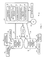
- FIG. 1 schematically illustrates one embodiment of a system for surgical modeling
- FIG. 2 schematically illustrates an embodiment of a prosthesis
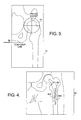
- FIG. 3 schematically illustrates an embodiment of anatomical landmarks identified on a two-dimensional image
- FIG. 4 illustrates an embodiment of a user interface displaying a two-dimensional representation of a three-dimensionally scaled prosthesis
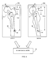
- FIG. 5 schematically illustrates embodiments of two-dimensional anatomical images from different perspectives
- FIG. 6 illustrates an embodiment of a user interface displaying a two-dimensional representation of a rotated version of the three-dimensionally scaled prosthesis of FIG. 4 ;
- FIG. 7 illustrates an embodiment of a user interface displaying a two-dimensional representation of a three-dimensionally scaled child prosthesis in relation to the prosthesis of FIG. 5 ;
- FIG. 8 illustrates an embodiment of a user interface displaying two-dimensional representations of multiple three-dimensionally scaled prostheses.
- FIGS. 9A and 9B illustrates one embodiment of creating procedure-based information as part of surgical modeling
- FIG. 10 illustrates another embodiment of creating procedure-based information as part of surgical modeling.
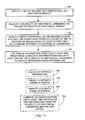
- FIG. 11 illustrates one embodiment of a method for surgical modeling.
- FIG. 1 schematically illustrates one embodiment of a system 20 for surgical modeling.
- the system 20 has a prosthesis knowledge-based information system 22.
- the prosthesis knowledge-based information system 22 may be a stand-alone database or set of machine-readable files which are directly accessible 26 or remotely accessible 28, for example via a network 30, by the system's controller 24.
- the prosthesis knowledge-based information system 22 may be a locally or internally available database or set of machine readable files.
- the prosthesis knowledge-based information system 22 may exist on a variety of computer readable media, including, but not limited to, randomly accessible memory (RAM), read-only memory (ROM), re-writeable flash memory, magnetic media, and optically readable/writeable media such as CD's and DVD's, or any combination thereof.
- RAM random accessible memory
- ROM read-only memory
- re-writeable flash memory magnetic media
- optically readable/writeable media such as CD's and DVD's, or any combination thereof.
- the one or more computer readable media for the prosthesis knowledge-based information system 22 may be permanently installed in the system 20 or removeably installed.
- the prosthesis knowledge-based information system 22 stores three-dimensional (3D) information associated with one or more prostheses.
- the prosthesis knowledge-based information system 22 may store information defining the volume, surface area, and shape of a prosthesis. Related anatomical information for the prosthesis may also be stored, such as definitions of rotation points for the prosthesis or one or more mechanical axes for the prosthesis.
- the prosthesis knowledge-based information system 22 may store display information for the prosthesis, such as notes on the usage and features of the prosthesis and measurements of the prosthesis.
- the prosthesis knowledge-based information system 22 may also store specific locations related to the prosthesis model which can be displayed on the model.
- the prosthesis knowledge-based information system 22 may further store prosthesis material information.
- the prosthesis knowledge-based information system 22 may store information which defines how one prosthesis (parent prosthesis) relates to another prosthesis (child prosthesis). Positional information for two or more related prostheses may be defined, prescribing their necessary locations relative to each other when used together and any possible degrees of freedom when moveable relative to one another.
- FIG. 2 illustrates one embodiment of several prosthesis elements which may be used in a hip replacement.
- a prosthesis stem 60 may be defined as a parent prosthesis, and its surface area, volume, and shape stored in the prosthesis knowledge-based information system 22.
- the prosthesis stem may have a mechanical axis 62 which is definable and displayable within the system 20.
- one of the other prosthesis elements is a prosthesis ball 64 which attaches to the neck 66 of the prosthesis stem.
- the ball 66 may be defined as a child prosthesis of the parent stem prosthesis 60, since the position of the ball 66 will be constrained by the position of the stem 60.
- a further prosthesis element in this embodiment is an acetabular cup 68 which can be installed in a pelvis socket.
- the acetabular cup 68 may have an associated center of rotation 70.
- Another prosthesis element in this embodiment is a bearing liner 72 which fits within the acetabular cup 68 to provide a bearing surface for the ball 64.
- the bearing liner 72 may be defined as a child prosthesis of the acetabular cup 68 or as a child of the stem 60 via the ball 64.
- the acetabular cup 68 may be defined as a child of the stem 60 via the ball 64 and the bearing liner 72 or as its own parent prosthesis having a defined relationship to the stem parent prosthesis.
- the relationship specified in the prosthesis knowledge-based information system 22 regarding the various parent and child prostheses defines how they interrelate to each other and how they are fixed or may move relative to each other.
- the information stored in the prosthesis knowledge-based information system 22 may be updated or provided by a prosthesis manufacturer 32 or by a physician, clinician, or researcher 34.
- the information stored in the prosthesis knowledge-based information system 22 may be provided by a 3 rd party 36, such as a service provider which is able to model existing prostheses for manufacturers or physicians who do not have that capability.
- the system 20 for surgical modeling also has a patient anatomical-based information system 38.
- the patient anatomical-based information system 38 may be a stand-alone database or set of machine-readable files which are directly accessible 40 or remotely accessible 42, for example via a network 30, by the system's controller 24.
- the patient anatomical-based information system 38 may be a locally or internally available database or set of machine readable files.
- the patient anatomical-based information system 38 may exist on a variety of computer readable media, including, but not limited to, randomly accessible memory (RAM), read-only memory (ROM), re-writeable flash memory, magnetic media, and optically readable/writeable media such as CD's and DVD's, or any combination thereof.
- the one or more computer readable media for the patient anatomical-based information system 38 may be permanently installed in the system 20 or removeably installed.
- the patient anatomical-based information system 38 stores information associated with the anatomy of one or more patients. This may include patient images such as x-rays 44 or a CT scan 46.
- the anatomical information stored in the patient anatomical-based information system 38 may also include anatomical landmarks and/or anatomical mechanical axes associated with one or more of the patient images.
- the patient anatomical-based information system 38 may also store notes on the patient as provided by a physician or other medical practitioner for example via a user interface 48 and/or the controller 24.
- the patient anatomical-based information system 38 may further store a link for each patient to one or more prostheses which have been selected for possible implantation in the patient from the prosthesis knowledge-based information system 22.
- the patient anatomical-based information system 38 may store information based on the patient's images 44, 46 and the associated one or more prostheses which is generated by the controller 24 during operation of the system 20.
- the specific types of information related to surgical modeling which the system 20 may develop will be discussed in more detail below as such functionality is discussed.
- the system also has a processor 24 which is capable of executing machine readable instructions, for example from a machine readable medium 50.
- a machine readable medium 50 include a diskette, a hard drive, an optical drive, a magnetic drive, a CD, a DVD, a flash memory, a RAM, a ROM, or any combination thereof.
- the machine readable medium 50 may be removable from the controller, remotely available to the controller 24, permanently installed in the controller 24, or integrated with the controller 24.
- the controller 24 may be a microprocessor, computer, application specific integrated circuit (ASIC), analog circuitry, digital circuitry, or any combination or plurality thereof.
- the controller 24 may be a single unit or may be a distributed device.
- the system 20 displays a set of related two-dimensional (2D) anatomical images on the user interface 48.
- the set of related 2D images may, for example, be patient x-rays or images from a patient CT scan. More than one of the set of related 2D anatomical images may be displayed on the user interface at a time, or a single image may be displayed at a time.
- the controller 24 has an anatomical landmark identifier 52. The actual anatomical landmarks which may be of interest can vary depending on the particular prosthesis being considered and the associated anatomy that the prosthesis would be replacing.
- the anatomical landmarks of interest may include a pelvis socket, a tear drop line, a greater trochanter, a lesser trochanter, a femoral head, a femoral ridge, and an anatomical mechanical axis.
- the anatomical landmark identifier 52 is configured to enable a user to identify one or more anatomical landmarks manually by indicating the position of the landmark in one or more images presented on the screen.
- the anatomical landmark identifier 52 may be configured to automatically identify some anatomical landmarks.
- Various automatic landmark identification methods are known to those skilled in the art.
- the anatomical landmark identifier 52 may be configured to identify anatomical landmarks using a combination of manual and automatic methods.
- the anatomical landmark identifier 52 may also be configured to enable the entry of measurements on the patient images for a representation of scale.
- FIG. 3 illustrates an example of two anatomical landmarks which have been identified on a two-dimensional anatomic image 74.
- the tear drop line 76 represents the true tilt/rotation of the pelvis within the image.
- the pelvis socket 78 is the center of rotation of the femur within the pelvis.
- the one or more 2D images 74 which are displayed to a user of the system may be original 2D images, such as x-rays or a 2D image slice from a 3D CT image set.
- the controller 24 is configured to allow a user to select one or more desired prostheses from the prosthesis knowledge-based information system 22.
- a 2D representation of the 3D prosthesis is displayed on the one or more patient images in the user interface 48.
- the controller 24 also has a prosthesis-to-anatomical-feature relator 54.
- the prosthesis-to-anatomical-feature relator 54 may be configured to scale the 3D prosthesis to match the scale of the anatomic image prior to creating the 2D representation.
- the prosthesis-to-anatomical-feature relator 54 may determine the scale of the image based on measurements from the anatomical landmark identifier 52. As an example, FIG.
- FIG. 4 illustrates an embodiment of a user interface displaying a two-dimensional representation of a three-dimensionally scaled prosthesis 80.
- the scaled prosthesis 80 may also include feature elements 82A, 82B which may schematically indicate one or more axes of rotation for the prosthesis 80.
- the user interface 48 may be configured to allow the scaled prosthesis 80 to be moved around within the image 84.
- the system may optionally have a 3D model generator 56.
- the 3D model generator 56 may be configured to utilize at least two images from the set of related 2D anatomical images to create a 3D anatomical model.
- FIG. 5 schematically illustrates two 2D anatomical images of a femur 88 having a 2D representation of a 3D prosthesis 90 overlaid on each of the views 86A, 86B.
- two anatomical landmarks 92, 94 have been identified on the views, and a scale between the anatomical landmarks 92, 94 determined.
- the 3D model generator can develop a fit of the known points to a variety of known 3D anatomical models or modify a closest-fit 3D model so that it complies with the known constraints from the 2D images.
- the result is a 3D anatomical model 96 which can be used for more accurate surgical planning.
- Various techniques are known to those skilled in the art to produce a three-dimensional model from a set of two-dimensional images.
- the 3D anatomical model 96 may include the anatomical landmarks 92, 94 located in 3D.
- the prosthesis-to-anatomical-feature relator 54 may display the relationship between the anatomical landmarks located in 3D to the 3D parent prosthesis.
- a hypothetical reference line on the prosthesis 90 such as a cut-line 91 may be automatically referenced relative to an anatomical landmark such as femur head 92.
- the distances relative to the cut line may be displayed, for example as in 93A, 93B, and 93C.
- the cut line 91 may be linked to the prosthesis per specifications from the prosthesis knowledge-based information system 22 and optionally, it may be modified by medical practitioner using the modeling system 20.
- the determination of a cut line for installation of a prosthesis is just one example of procedure based information which is created by the system.
- Embodiments which develop a 3D anatomical model 96 may also be configured to enable the prosthesis-to-anatomical-feature relator 54 to determine a 3D relationship between the 3D anatomical model 96 and a 3D prosthesis model from the prosthesis knowledge-based information system 22. By determining the relationships in three-dimensions the prosthesis-to-anatomical-feature relator 54 may then develop highly accurate 2D representations of the 3D relationship which do not suffer from the limitations of the prior art which have been discussed above. Utilizing the accurate 3D relationships between the anatomical model 96 and the prosthesis, the system may be configured not only to move the prosthesis within the different images, but to rotate the prosthesis, for example, with six degrees of freedom.
- FIG. 6 illustrates an embodiment of a user interface displaying a two-dimensional representation of a rotated version of the three-dimensionally scaled prosthesis of FIG. 4 .
- the axis lines 82A, 82B from FIG. 4 have been aligned in the view of FIG. 6 , while the prosthesis 80 in the 2D view 98 has been accurately adjusted based on the 3D calculations based on the relationship between the 3D anatomical model 96 and the 3D prosthesis model.
- the processor 24 may optionally have a prosthesis-parent-to-prosthesis-child relator 58.
- the prosthesis-parent-to-prosthesis-child relator 58 may be configured to determine a 3D relationship between a parent prosthesis model and a child prosthesis model from the prosthesis knowledge-based information system 22 as well as from the 3D anatomical model.
- FIG. 7 illustrates, once the parent prosthesis 80 has been placed and its position is known in 3D, a child prosthesis 100 may be included in the 3D model according to its constraints. In the case of child prosthesis 100 (a ball), the child prosthesis is fixed relative to the parent prosthesis 80 (a stem).
- FIG. 8 illustrates the idea that there may be multiple children prostheses 100, 102, 104 which may be associated to a parent prosthesis 80.
- the prosthesis knowledge-based information system 22 may define the range of motion between various prosthesis, so that, in this example the bearing liner 102 and acetabular cup 104 could be manipulated within the image only to locations compatible with the ball 100 and stem 80 location.
- certain prostheses may be defined in the prosthesis knowledge-based information system 22 as both a parent and as a child prosthesis. For example, the acetabular cup 104 of FIG.
- the bearing liner 102 could be a child prosthesis of the acetabular cup 104.
- the stem 80 could be a separate parent prosthesis which defines where ball 100 will end up.
- the cup 104 and liner 102 may be made child prostheses of the stem prosthesis for the purpose of determining whether the chosen placement is within a desired specification. If the placement of the prosthesis does not fall within the allowed relationship specified by the prosthesis knowledge-based information system 22, then a warning could be displayed to the user or a corrective shift could be forced on the prosthesis.
- the system also has a procedure modeler 59.
- the procedure modeler 59 utilizes 3D information from the at least one prosthesis along with information based on at least one of the plurality of anatomical landmarks to create procedure-based information.
- calculating procedure-based information may include calculating surgical information.
- the surgical information could include determining the amount of bone removal necessary for implantation of the prosthesis. This can include determining a bone cut line as has been demonstrated and/or determining a volume of bone which needs to be removed from the remaining bone. This could be implemented by determining the intersection of the 3D anatomical model with the 3D prosthesis.
- calculating procedure-based information may include determining a prosthesis insertion path.
- calculating procedure-based information may include determining an area of bone contact with at least one prosthesis. This can be determined in the 3D space by calculating the surface area of the prosthesis where it intersects with the bone of the 3D anatomical model. Knowing the prosthesis contact area may also enable the system 20 to determine an amount of cement which may be needed to attach the prosthesis to the bone it is in contact with.
- Further embodiments may specify a desired location for the cement to contact the prosthesis, and the system 20 can be configured to display the cement contact locations as well as determine whether or not the cement locations will actually be in contact with the bone. Again, this is made possible by the 3D comparisons between the 3D prosthesis model and the 3D anatomical model.
- the procedure-based information created by the system may be generated by comparing information from the at least one prosthesis with information from the plurality of anatomical landmarks.
- FIG. 9A illustrates an embodiment of a before analysis
- FIG 9B illustrates an embodiment of an after analysis with respect to a prosthesis implantation.
- a tear drop line 106 and a pelvis socket 108 have been identified as anatomical landmarks.
- the pelvis socket 108 may be projected 110 down to the tear drop line 106.
- a prosthesis stem 112 and its related prosthesis acetabular cup 114 may be scaled in 3D and placed within the patient image set as illustrated in FIG. 9B .
- the center of the acetabular cup may be projected down 116 to the tear drop line 106.
- the difference between where each projection 110, 116 intersects the tear drop line 106 is the lateral offset 118 or the delta change which takes place.
- the modeling system 20 enables such before and after comparisons by comparing the prosthesis with the anatomical landmarks.
- the procedure-based information created by the system may include predicting a patient's range of motion based on a range of motion of the parent prosthesis and one or more child prostheses and a relationship between the parent prosthesis, the one or more child prostheses, and the 3D anatomical model.
- FIG. 10 schematically illustrates one embodiment of a user interface 120 which shows a baseline femur position 122 in a solid line and a laterally pivoted femur 124 in a broken line.
- the procedure modeler 59 may be configured to enable such manipulations to be demonstrated on-screen while using the 3D anatomical model to ensure that the different bone elements are not occupying the same space (for example, see position 126 where a top portion of the femur would contact the pelvis if it were rotated further. Additionally, the procedure modeler 59 can be configured to maintain a position of the prosthesis 128 relative to the bone 130 it is attached to. The system 20 may also be configured to compare a starting angle 132 to an ending angle 134 to determine a range 136 of motion. Further embodiments may be configured to animate this motion over a particular range.
- the system 20 and its equivalents provide a medical practitioner with the ability to effectively model a surgical procedure by allowing them to test-fit various prostheses from the prosthesis knowledge-based information system 22 on a 2D or a 3D anatomical model of a subject patient while determining key procedure-based information to see if the prosthesis that fits will work and install properly. Performing the relational calculations in three-dimensions before creating the two-dimensional representations for view by the user ensure that differences in rotation, scaling, and perspective are accounted-for.
- FIG. 11 illustrates one embodiment of a method for surgical modeling.
- a set of related two-dimensional (2D) anatomical images are displayed 138.
- the set of images may be displayed all at the same time, one at a time, or more than one at a time via a user interface.
- the 2D images may come from a variety of 2D or 3D sources, such as x-rays or a CT Scan.
- a plurality of anatomical landmarks are identified 140 on the set of 2D anatomical images. If the 2D anatomical images came from a 3D image set, then a 3D anatomical model may already be available.
- a three dimensional (3D) representation of a parent prosthesis is scaled 142 to match a scale of the 2D anatomical images based at least in part on a relationship between the anatomical landmarks.
- procedure-based information is created 144. As discussed above, this may include calculating surgical information 146, predicting a patient's range of motion 148, animating a patient's range of motion 150, and/or comparing 152 information from the at least one prosthesis with information from the plurality of anatomical landmarks, for example to obtain a before and after picture of the prosthesis implantation.
Landscapes
- Health & Medical Sciences (AREA)
- Transplantation (AREA)
- Orthopedic Medicine & Surgery (AREA)
- Heart & Thoracic Surgery (AREA)
- Life Sciences & Earth Sciences (AREA)
- Oral & Maxillofacial Surgery (AREA)
- Engineering & Computer Science (AREA)
- Biomedical Technology (AREA)
- Physical Education & Sports Medicine (AREA)
- Vascular Medicine (AREA)
- Cardiology (AREA)
- Animal Behavior & Ethology (AREA)
- General Health & Medical Sciences (AREA)
- Public Health (AREA)
- Veterinary Medicine (AREA)
- Apparatus For Radiation Diagnosis (AREA)
- Processing Or Creating Images (AREA)
- Measuring And Recording Apparatus For Diagnosis (AREA)
Applications Claiming Priority (1)
| Application Number | Priority Date | Filing Date | Title |
|---|---|---|---|
| US12/287,325 US8160326B2 (en) | 2008-10-08 | 2008-10-08 | Method and system for surgical modeling |
Publications (3)
| Publication Number | Publication Date |
|---|---|
| EP2175418A2 true EP2175418A2 (fr) | 2010-04-14 |
| EP2175418A3 EP2175418A3 (fr) | 2011-05-11 |
| EP2175418B1 EP2175418B1 (fr) | 2015-08-05 |
Family
ID=41435301
Family Applications (1)
| Application Number | Title | Priority Date | Filing Date |
|---|---|---|---|
| EP09012766.3A Not-in-force EP2175418B1 (fr) | 2008-10-08 | 2009-10-08 | Procédé et système de modélisation chirurgicale |
Country Status (3)
| Country | Link |
|---|---|
| US (2) | US8160326B2 (fr) |
| EP (1) | EP2175418B1 (fr) |
| JP (1) | JP2010088892A (fr) |
Cited By (4)
| Publication number | Priority date | Publication date | Assignee | Title |
|---|---|---|---|---|
| EP2805277A4 (fr) * | 2012-01-16 | 2015-10-14 | Emovi Inc | Procédé et système pour un plan de traitement et une planification de chirurgie personnalisée d'articulation pour un patient humain à l'aide de cinématique 3d, simulation et imagerie de fusion |
| EP3057018A1 (fr) * | 2012-03-30 | 2016-08-17 | Sandance Technology LLC | Systèmes et procédés permettant de déterminer la compatibilité d'un implant pour une procédure médicale spécifiée |
| US10987176B2 (en) | 2018-06-19 | 2021-04-27 | Tornier, Inc. | Virtual guidance for orthopedic surgical procedures |
| US12465374B2 (en) | 2019-12-18 | 2025-11-11 | Howmedica Osteonics Corp. | Surgical guidance for surgical tools |
Families Citing this family (30)
| Publication number | Priority date | Publication date | Assignee | Title |
|---|---|---|---|---|
| US8160345B2 (en) | 2008-04-30 | 2012-04-17 | Otismed Corporation | System and method for image segmentation in generating computer models of a joint to undergo arthroplasty |
| US8078440B2 (en) | 2008-09-19 | 2011-12-13 | Smith & Nephew, Inc. | Operatively tuning implants for increased performance |
| US9262802B2 (en) | 2010-07-21 | 2016-02-16 | Arthromeda, Inc. | Independent digital templating software, and methods and systems using same |
| JP2013537455A (ja) * | 2010-08-13 | 2013-10-03 | スミス アンド ネフュー インコーポレーテッド | 整形外科的処置のパラメータを最適化するシステムおよび方法 |
| US9173716B2 (en) | 2011-11-08 | 2015-11-03 | Mako Surgical Corporation | Computer-aided planning with dual alpha angles in femoral acetabular impingement surgery |
| US20140081659A1 (en) * | 2012-09-17 | 2014-03-20 | Depuy Orthopaedics, Inc. | Systems and methods for surgical and interventional planning, support, post-operative follow-up, and functional recovery tracking |
| SE536759C2 (sv) * | 2012-10-18 | 2014-07-15 | Ortoma Ab | Metod och system för planering av position för implantatkomponent |
| JP6057305B2 (ja) * | 2012-10-31 | 2017-01-11 | 国立大学法人浜松医科大学 | 骨盤回旋角度算出装置及び骨盤回旋角度算出方法、臼蓋被覆3次元形状推定装置及び臼蓋被覆3次元形状推定方法、骨盤回旋角度算出プログラム、並びに臼蓋被覆3次元形状推定プログラム |
| JP2014097220A (ja) * | 2012-11-15 | 2014-05-29 | Toshiba Corp | 手術支援装置 |
| EP2996589B1 (fr) | 2013-03-15 | 2022-01-19 | Howmedica Osteonics Corporation | Génération d'un modèle de surface d'accouplement pour un guide de coupe spécifique au patient sur la base d'une segmentation de modèle anatomique |
| US20160296289A1 (en) * | 2013-03-15 | 2016-10-13 | Concepto Llc | Custom matched joint prosthesis replacement |
| GB2532614B8 (en) | 2013-05-02 | 2020-07-08 | Hu Yangqiu | Surface and image integration for model evaluation and landmark determination |
| DE102013109057A1 (de) * | 2013-08-21 | 2015-02-26 | Hectec Gmbh | Verfahren zur Planung und Vorbereitung eines operativen Eingriffs in den menschlichen oder tierischen Körper, Vorrichtung zum Ausführen eines solchen Eingriffs und Verwendung der Vorrichtung |
| JP2017507689A (ja) * | 2014-01-10 | 2017-03-23 | アーオー テクノロジー アクチエンゲゼルシャフト | 少なくとも1つの解剖学的構造の3d参照コンピュータモデルを生成するための方法 |
| US12295772B2 (en) | 2014-02-25 | 2025-05-13 | DePuy Synthes Products, Inc. | Systems and methods for intra-operative image analysis |
| US10758198B2 (en) * | 2014-02-25 | 2020-09-01 | DePuy Synthes Products, Inc. | Systems and methods for intra-operative image analysis |
| US10433914B2 (en) | 2014-02-25 | 2019-10-08 | JointPoint, Inc. | Systems and methods for intra-operative image analysis |
| US9757245B2 (en) * | 2014-04-24 | 2017-09-12 | DePuy Synthes Products, Inc. | Patient-specific spinal fusion cage and methods of making same |
| WO2016115306A1 (fr) * | 2015-01-15 | 2016-07-21 | Think Surgical, Inc. | Commande à guidage par image et laser pour découpe à l'aide d'un système chirurgical robotique |
| US10117713B2 (en) | 2015-07-01 | 2018-11-06 | Mako Surgical Corp. | Robotic systems and methods for controlling a tool removing material from a workpiece |
| US10182871B2 (en) | 2016-05-22 | 2019-01-22 | JointPoint, Inc. | Systems and methods for intra-operative image acquisition and calibration |
| US10667867B2 (en) | 2017-05-03 | 2020-06-02 | Stryker European Holdings I, Llc | Methods of pose estimation of three-dimensional bone models in surgical planning a total ankle replacement |
| WO2020033656A1 (fr) * | 2018-08-08 | 2020-02-13 | Loyola University Chicago | Procédés de classification et/ou de détermination d'orientations d'objets à l'aide d'images bidimensionnelles |
| CN111292363B (zh) * | 2020-02-13 | 2022-02-22 | 张逸凌 | 一种关节图像处理方法、装置和计算设备 |
| CN111616725A (zh) * | 2020-05-12 | 2020-09-04 | 余刚 | 一种髋关节假体的尺寸匹配方法 |
| US11107586B1 (en) | 2020-06-24 | 2021-08-31 | Cuptimize, Inc. | System and method for analyzing acetabular cup position |
| US12611254B2 (en) | 2020-12-31 | 2026-04-28 | Depuy Ireland Unlimited Company | Apparatus, system, and method for determining a position of a hip prosthesis in a bone of a patient |
| US11887306B2 (en) | 2021-08-11 | 2024-01-30 | DePuy Synthes Products, Inc. | System and method for intraoperatively determining image alignment |
| KR102903650B1 (ko) * | 2023-01-28 | 2025-12-22 | 동국대학교 산학협력단 | 인공 뼈 모델의 제조 장치 및 제조 방법 |
| CN116650110B (zh) * | 2023-06-12 | 2024-05-07 | 北京长木谷医疗科技股份有限公司 | 基于深度强化学习的膝关节假体自动放置方法及装置 |
Citations (2)
| Publication number | Priority date | Publication date | Assignee | Title |
|---|---|---|---|---|
| WO2000041626A1 (fr) | 1999-01-15 | 2000-07-20 | Z-Kat, Inc. | Appareil et procede de mesure d'objets anatomiques avec radioscopie de coordonnees |
| WO2004001569A2 (fr) | 2002-06-21 | 2003-12-31 | Cedara Software Corp. | Systeme et procede assistes par ordinateur de remplacement de hanche, de remplacement partiel de genou et de remplacement complet de genou a invasion minimale |
Family Cites Families (27)
| Publication number | Priority date | Publication date | Assignee | Title |
|---|---|---|---|---|
| US4436684A (en) * | 1982-06-03 | 1984-03-13 | Contour Med Partners, Ltd. | Method of forming implantable prostheses for reconstructive surgery |
| US5682886A (en) * | 1995-12-26 | 1997-11-04 | Musculographics Inc | Computer-assisted surgical system |
| US5824085A (en) * | 1996-09-30 | 1998-10-20 | Integrated Surgical Systems, Inc. | System and method for cavity generation for surgical planning and initial placement of a bone prosthesis |
| US6177034B1 (en) * | 1998-04-03 | 2001-01-23 | A-Pear Biometric Replications Inc. | Methods for making prosthetic surfaces |
| DE60109541T2 (de) * | 2000-09-18 | 2006-02-16 | Fuji Photo Film Co., Ltd., Minami-Ashigara | System zum Auswählen, Anzeigen und Speichern von Kunstknochenschablonen und Aufzeichnungsträger dafür |
| EP1371020A2 (fr) * | 2001-01-29 | 2003-12-17 | The Acrobot Company Limited | Modelisation en chirurgie |
| US7630750B2 (en) * | 2001-02-05 | 2009-12-08 | The Research Foundation For The State University Of New York | Computer aided treatment planning |
| CA2334495A1 (fr) * | 2001-02-06 | 2002-08-06 | Surgical Navigation Specialists, Inc. | Methode et systeme de positionnement assistes par ordinateur |
| JP2003144454A (ja) * | 2001-11-16 | 2003-05-20 | Yoshio Koga | 関節手術支援情報算出方法、関節手術支援情報算出プログラム、及び関節手術支援情報算出システム |
| NO315217B1 (no) * | 2002-02-08 | 2003-07-28 | Scandinavian Customized Prosth | System og fremgangsmåte for utarbeidelse og overföring av spesifikasjoner for pasienttilpassede proteser |
| GB2393625C (en) | 2002-09-26 | 2004-08-18 | Meridian Tech Ltd | Orthopaedic surgery planning |
| US7542791B2 (en) * | 2003-01-30 | 2009-06-02 | Medtronic Navigation, Inc. | Method and apparatus for preplanning a surgical procedure |
| FI117986B (fi) * | 2003-06-17 | 2007-05-15 | Onesys Oy | Menetelmä ja järjestelmä navigoimiseksi tosiaikaisesti kolmiulotteisessa lääketieteellisessä kuvamallissa |
| US20050038338A1 (en) * | 2003-08-11 | 2005-02-17 | Bono James Vincent | Pre-operative planning of implantations |
| US8484001B2 (en) * | 2003-08-26 | 2013-07-09 | Voyant Health Ltd. | Pre-operative medical planning system and method for use thereof |
| US7346201B2 (en) * | 2003-09-26 | 2008-03-18 | Virtualscopics Llc | Semi-automated measurement of anatomical structures using statistical and morphological priors |
| US20060098010A1 (en) * | 2004-03-09 | 2006-05-11 | Jeff Dwyer | Anatomical visualization and measurement system |
| JP2005287813A (ja) * | 2004-03-31 | 2005-10-20 | National Institute Of Advanced Industrial & Technology | 人工医用材料の最適形状検索システム |
| WO2005099636A1 (fr) * | 2004-03-31 | 2005-10-27 | Niigata Tlo Corporation | Tige intra-médullaire pour assistance dans une opération de remplacement de genou prothétique et méthode pour gérer l'opération à l'aide de cette tige |
| US7394946B2 (en) * | 2004-05-18 | 2008-07-01 | Agfa Healthcare | Method for automatically mapping of geometric objects in digital medical images |
| GB0504172D0 (en) | 2005-03-01 | 2005-04-06 | King S College London | Surgical planning |
| JP4507097B2 (ja) * | 2005-03-24 | 2010-07-21 | 国立大学法人大阪大学 | 形態評価と機能評価の最適バランスに基づくインプラント三次元手術計画システム |
| US7480402B2 (en) * | 2005-04-20 | 2009-01-20 | Visionsense Ltd. | System and method for producing an augmented image of an organ of a patient |
| US20070066917A1 (en) * | 2005-09-20 | 2007-03-22 | Hodorek Robert A | Method for simulating prosthetic implant selection and placement |
| JP2007229312A (ja) * | 2006-03-02 | 2007-09-13 | Canon Inc | 手術計画システム、及び、手術計画装置及びその制御方法、並びに、コンピュータプログラム及びコンピュータ可読記憶媒体 |
| US7855723B2 (en) * | 2006-03-21 | 2010-12-21 | Biosense Webster, Inc. | Image registration using locally-weighted fitting |
| US8660635B2 (en) * | 2006-09-29 | 2014-02-25 | Medtronic, Inc. | Method and apparatus for optimizing a computer assisted surgical procedure |
-
2008
- 2008-10-08 US US12/287,325 patent/US8160326B2/en active Active
-
2009
- 2009-10-08 JP JP2009234539A patent/JP2010088892A/ja active Pending
- 2009-10-08 EP EP09012766.3A patent/EP2175418B1/fr not_active Not-in-force
-
2012
- 2012-03-19 US US13/423,345 patent/US8750583B2/en active Active
Patent Citations (2)
| Publication number | Priority date | Publication date | Assignee | Title |
|---|---|---|---|---|
| WO2000041626A1 (fr) | 1999-01-15 | 2000-07-20 | Z-Kat, Inc. | Appareil et procede de mesure d'objets anatomiques avec radioscopie de coordonnees |
| WO2004001569A2 (fr) | 2002-06-21 | 2003-12-31 | Cedara Software Corp. | Systeme et procede assistes par ordinateur de remplacement de hanche, de remplacement partiel de genou et de remplacement complet de genou a invasion minimale |
Cited By (22)
| Publication number | Priority date | Publication date | Assignee | Title |
|---|---|---|---|---|
| EP2805277A4 (fr) * | 2012-01-16 | 2015-10-14 | Emovi Inc | Procédé et système pour un plan de traitement et une planification de chirurgie personnalisée d'articulation pour un patient humain à l'aide de cinématique 3d, simulation et imagerie de fusion |
| EP3057018A1 (fr) * | 2012-03-30 | 2016-08-17 | Sandance Technology LLC | Systèmes et procédés permettant de déterminer la compatibilité d'un implant pour une procédure médicale spécifiée |
| US10987176B2 (en) | 2018-06-19 | 2021-04-27 | Tornier, Inc. | Virtual guidance for orthopedic surgical procedures |
| US11439469B2 (en) | 2018-06-19 | 2022-09-13 | Howmedica Osteonics Corp. | Virtual guidance for orthopedic surgical procedures |
| US11478310B2 (en) | 2018-06-19 | 2022-10-25 | Howmedica Osteonics Corp. | Virtual guidance for ankle surgery procedures |
| US11571263B2 (en) | 2018-06-19 | 2023-02-07 | Howmedica Osteonics Corp. | Mixed-reality surgical system with physical markers for registration of virtual models |
| US11645531B2 (en) | 2018-06-19 | 2023-05-09 | Howmedica Osteonics Corp. | Mixed-reality surgical system with physical markers for registration of virtual models |
| US11657287B2 (en) | 2018-06-19 | 2023-05-23 | Howmedica Osteonics Corp. | Virtual guidance for ankle surgery procedures |
| US12020801B2 (en) | 2018-06-19 | 2024-06-25 | Howmedica Osteonics Corp. | Virtual guidance for orthopedic surgical procedures |
| US12046349B2 (en) | 2018-06-19 | 2024-07-23 | Howmedica Osteonics Corp. | Visualization of intraoperatively modified surgical plans |
| US12050999B2 (en) | 2018-06-19 | 2024-07-30 | Howmedica Osteonics Corp. | Virtual guidance for orthopedic surgical procedures |
| US12112269B2 (en) | 2018-06-19 | 2024-10-08 | Howmedica Osteonics Corp. | Mixed reality-aided surgical assistance in orthopedic surgical procedures |
| US12112843B2 (en) | 2018-06-19 | 2024-10-08 | Howmedica Osteonics Corp. | Mixed reality-aided education related to orthopedic surgical procedures |
| US12125577B2 (en) | 2018-06-19 | 2024-10-22 | Howmedica Osteonics Corp. | Mixed reality-aided education using virtual models or virtual representations for orthopedic surgical procedures |
| US12148518B2 (en) | 2018-06-19 | 2024-11-19 | Howmedica Osteonics Corp. | Neural network for recommendation of shoulder surgery type |
| US12170139B2 (en) | 2018-06-19 | 2024-12-17 | Howmedica Osteonics Corp. | Virtual checklists for orthopedic surgery |
| US12237066B2 (en) | 2018-06-19 | 2025-02-25 | Howmedica Osteonics Corp. | Multi-user collaboration and workflow techniques for orthopedic surgical procedures using mixed reality |
| US12266440B2 (en) | 2018-06-19 | 2025-04-01 | Howmedica Osteonics Corp. | Automated instrument or component assistance using mixed reality in orthopedic surgical procedures |
| US12347545B2 (en) | 2018-06-19 | 2025-07-01 | Howmedica Osteonics Corp. | Automated instrument or component assistance using externally controlled light sources in orthopedic surgical procedures |
| US12362057B2 (en) | 2018-06-19 | 2025-07-15 | Howmedica Osteonics Corp. | Virtual guidance for orthopedic surgical procedures |
| US12380986B2 (en) | 2018-06-19 | 2025-08-05 | Howmedica Osteonics Corp. | Virtual guidance for orthopedic surgical procedures |
| US12465374B2 (en) | 2019-12-18 | 2025-11-11 | Howmedica Osteonics Corp. | Surgical guidance for surgical tools |
Also Published As
| Publication number | Publication date |
|---|---|
| US8160326B2 (en) | 2012-04-17 |
| EP2175418A3 (fr) | 2011-05-11 |
| US20100086181A1 (en) | 2010-04-08 |
| US20120177264A1 (en) | 2012-07-12 |
| EP2175418B1 (fr) | 2015-08-05 |
| JP2010088892A (ja) | 2010-04-22 |
| US8750583B2 (en) | 2014-06-10 |
Similar Documents
| Publication | Publication Date | Title |
|---|---|---|
| US8160326B2 (en) | Method and system for surgical modeling | |
| EP2175419B1 (fr) | Procédé et système de planification chirurgicale | |
| US12161428B1 (en) | System for computation of object coordinates accounting for movement of a surgical site for spinal and other procedures including interpolation of vertebral position and orientation | |
| JP7532416B2 (ja) | 外科手術に拡張現実を利用するためのシステム及び方法 | |
| US11615531B2 (en) | Devices and methods for anatomic mapping for prosthetic implants | |
| CN110584776B (zh) | 定制交互控制边界的方法和计算机辅助外科手术系统 | |
| US20220079675A1 (en) | Augmented Reality Guidance for Surgical Procedures with Adjustment of Scale, Convergence and Focal Plane or Focal Point of Virtual Data | |
| US8331634B2 (en) | Method for virtual adaptation of an implant to a body part of a patient | |
| US7388972B2 (en) | Orthopaedic surgery planning | |
| EP2778998B1 (fr) | Génération d'un plan chirurgical à partir de données d'image médicale | |
| CN104994803B (zh) | 利用图像数据来放置部件的系统和方法 | |
| CA3049662A1 (fr) | Guidage optique pour procedures chirurgicales, medicales et dentaires | |
| CA3016604A1 (fr) | Dispositifs et methodes pour chirurgie | |
| AU2019247799A1 (en) | Implant alignment system | |
| CN114072087A (zh) | 整形外科植入物放置系统和方法 | |
| US20250107904A1 (en) | Apparatus, system, and method for determining a position of a hip prosthesis in a bone of a patient | |
| Lattanzi et al. | Applications of 3D Medical Imaging in Orthopaedic Surgery: Introducing the Hip-Op System. | |
| US20250302416A1 (en) | Systems and methods for generating and presenting predictive synthetic x-ray images | |
| WO2025208021A1 (fr) | Systèmes et procédés de génération et de présentation d'images radiographiques synthétiques prédictives |
Legal Events
| Date | Code | Title | Description |
|---|---|---|---|
| PUAI | Public reference made under article 153(3) epc to a published international application that has entered the european phase |
Free format text: ORIGINAL CODE: 0009012 |
|
| AK | Designated contracting states |
Kind code of ref document: A2 Designated state(s): AT BE BG CH CY CZ DE DK EE ES FI FR GB GR HR HU IE IS IT LI LT LU LV MC MK MT NL NO PL PT RO SE SI SK SM TR |
|
| AX | Request for extension of the european patent |
Extension state: AL BA RS |
|
| REG | Reference to a national code |
Ref country code: DE Ref legal event code: R079 Ref document number: 602009032626 Country of ref document: DE Free format text: PREVIOUS MAIN CLASS: G06T0007000000 Ipc: A61F0002460000 |
|
| PUAL | Search report despatched |
Free format text: ORIGINAL CODE: 0009013 |
|
| AK | Designated contracting states |
Kind code of ref document: A3 Designated state(s): AT BE BG CH CY CZ DE DK EE ES FI FR GB GR HR HU IE IS IT LI LT LU LV MC MK MT NL NO PL PT RO SE SI SK SM TR |
|
| AX | Request for extension of the european patent |
Extension state: AL BA RS |
|
| RIC1 | Information provided on ipc code assigned before grant |
Ipc: A61F 2/32 20060101ALN20110407BHEP Ipc: A61F 2/46 20060101AFI20110407BHEP Ipc: A61B 19/00 20060101ALN20110407BHEP |
|
| 17P | Request for examination filed |
Effective date: 20111111 |
|
| 17Q | First examination report despatched |
Effective date: 20131127 |
|
| GRAP | Despatch of communication of intention to grant a patent |
Free format text: ORIGINAL CODE: EPIDOSNIGR1 |
|
| INTG | Intention to grant announced |
Effective date: 20150212 |
|
| GRAS | Grant fee paid |
Free format text: ORIGINAL CODE: EPIDOSNIGR3 |
|
| GRAA | (expected) grant |
Free format text: ORIGINAL CODE: 0009210 |
|
| AK | Designated contracting states |
Kind code of ref document: B1 Designated state(s): AT BE BG CH CY CZ DE DK EE ES FI FR GB GR HR HU IE IS IT LI LT LU LV MC MK MT NL NO PL PT RO SE SI SK SM TR |
|
| REG | Reference to a national code |
Ref country code: GB Ref legal event code: FG4D |
|
| REG | Reference to a national code |
Ref country code: DE Ref legal event code: R082 Ref document number: 602009032626 Country of ref document: DE Representative=s name: WAGNER & GEYER PARTNERSCHAFT MBB PATENT- UND R, DE |
|
| REG | Reference to a national code |
Ref country code: CH Ref legal event code: EP |
|
| REG | Reference to a national code |
Ref country code: AT Ref legal event code: REF Ref document number: 740248 Country of ref document: AT Kind code of ref document: T Effective date: 20150815 |
|
| REG | Reference to a national code |
Ref country code: IE Ref legal event code: FG4D |
|
| REG | Reference to a national code |
Ref country code: DE Ref legal event code: R096 Ref document number: 602009032626 Country of ref document: DE |
|
| REG | Reference to a national code |
Ref country code: FR Ref legal event code: PLFP Year of fee payment: 7 |
|
| REG | Reference to a national code |
Ref country code: AT Ref legal event code: MK05 Ref document number: 740248 Country of ref document: AT Kind code of ref document: T Effective date: 20150805 |
|
| REG | Reference to a national code |
Ref country code: LT Ref legal event code: MG4D |
|
| REG | Reference to a national code |
Ref country code: NL Ref legal event code: MP Effective date: 20150805 |
|
| PG25 | Lapsed in a contracting state [announced via postgrant information from national office to epo] |
Ref country code: LT Free format text: LAPSE BECAUSE OF FAILURE TO SUBMIT A TRANSLATION OF THE DESCRIPTION OR TO PAY THE FEE WITHIN THE PRESCRIBED TIME-LIMIT Effective date: 20150805 Ref country code: GR Free format text: LAPSE BECAUSE OF FAILURE TO SUBMIT A TRANSLATION OF THE DESCRIPTION OR TO PAY THE FEE WITHIN THE PRESCRIBED TIME-LIMIT Effective date: 20151106 Ref country code: NO Free format text: LAPSE BECAUSE OF FAILURE TO SUBMIT A TRANSLATION OF THE DESCRIPTION OR TO PAY THE FEE WITHIN THE PRESCRIBED TIME-LIMIT Effective date: 20151105 Ref country code: FI Free format text: LAPSE BECAUSE OF FAILURE TO SUBMIT A TRANSLATION OF THE DESCRIPTION OR TO PAY THE FEE WITHIN THE PRESCRIBED TIME-LIMIT Effective date: 20150805 Ref country code: LV Free format text: LAPSE BECAUSE OF FAILURE TO SUBMIT A TRANSLATION OF THE DESCRIPTION OR TO PAY THE FEE WITHIN THE PRESCRIBED TIME-LIMIT Effective date: 20150805 |
|
| PG25 | Lapsed in a contracting state [announced via postgrant information from national office to epo] |
Ref country code: AT Free format text: LAPSE BECAUSE OF FAILURE TO SUBMIT A TRANSLATION OF THE DESCRIPTION OR TO PAY THE FEE WITHIN THE PRESCRIBED TIME-LIMIT Effective date: 20150805 Ref country code: PL Free format text: LAPSE BECAUSE OF FAILURE TO SUBMIT A TRANSLATION OF THE DESCRIPTION OR TO PAY THE FEE WITHIN THE PRESCRIBED TIME-LIMIT Effective date: 20150805 Ref country code: PT Free format text: LAPSE BECAUSE OF FAILURE TO SUBMIT A TRANSLATION OF THE DESCRIPTION OR TO PAY THE FEE WITHIN THE PRESCRIBED TIME-LIMIT Effective date: 20151207 Ref country code: ES Free format text: LAPSE BECAUSE OF FAILURE TO SUBMIT A TRANSLATION OF THE DESCRIPTION OR TO PAY THE FEE WITHIN THE PRESCRIBED TIME-LIMIT Effective date: 20150805 Ref country code: HR Free format text: LAPSE BECAUSE OF FAILURE TO SUBMIT A TRANSLATION OF THE DESCRIPTION OR TO PAY THE FEE WITHIN THE PRESCRIBED TIME-LIMIT Effective date: 20150805 Ref country code: SE Free format text: LAPSE BECAUSE OF FAILURE TO SUBMIT A TRANSLATION OF THE DESCRIPTION OR TO PAY THE FEE WITHIN THE PRESCRIBED TIME-LIMIT Effective date: 20150805 Ref country code: IS Free format text: LAPSE BECAUSE OF FAILURE TO SUBMIT A TRANSLATION OF THE DESCRIPTION OR TO PAY THE FEE WITHIN THE PRESCRIBED TIME-LIMIT Effective date: 20151205 |
|
| PG25 | Lapsed in a contracting state [announced via postgrant information from national office to epo] |
Ref country code: NL Free format text: LAPSE BECAUSE OF FAILURE TO SUBMIT A TRANSLATION OF THE DESCRIPTION OR TO PAY THE FEE WITHIN THE PRESCRIBED TIME-LIMIT Effective date: 20150805 |
|
| PG25 | Lapsed in a contracting state [announced via postgrant information from national office to epo] |
Ref country code: EE Free format text: LAPSE BECAUSE OF FAILURE TO SUBMIT A TRANSLATION OF THE DESCRIPTION OR TO PAY THE FEE WITHIN THE PRESCRIBED TIME-LIMIT Effective date: 20150805 Ref country code: SK Free format text: LAPSE BECAUSE OF FAILURE TO SUBMIT A TRANSLATION OF THE DESCRIPTION OR TO PAY THE FEE WITHIN THE PRESCRIBED TIME-LIMIT Effective date: 20150805 Ref country code: DK Free format text: LAPSE BECAUSE OF FAILURE TO SUBMIT A TRANSLATION OF THE DESCRIPTION OR TO PAY THE FEE WITHIN THE PRESCRIBED TIME-LIMIT Effective date: 20150805 Ref country code: CZ Free format text: LAPSE BECAUSE OF FAILURE TO SUBMIT A TRANSLATION OF THE DESCRIPTION OR TO PAY THE FEE WITHIN THE PRESCRIBED TIME-LIMIT Effective date: 20150805 Ref country code: IT Free format text: LAPSE BECAUSE OF FAILURE TO SUBMIT A TRANSLATION OF THE DESCRIPTION OR TO PAY THE FEE WITHIN THE PRESCRIBED TIME-LIMIT Effective date: 20150805 |
|
| REG | Reference to a national code |
Ref country code: DE Ref legal event code: R097 Ref document number: 602009032626 Country of ref document: DE |
|
| PG25 | Lapsed in a contracting state [announced via postgrant information from national office to epo] |
Ref country code: RO Free format text: LAPSE BECAUSE OF FAILURE TO SUBMIT A TRANSLATION OF THE DESCRIPTION OR TO PAY THE FEE WITHIN THE PRESCRIBED TIME-LIMIT Effective date: 20150805 Ref country code: LU Free format text: LAPSE BECAUSE OF FAILURE TO SUBMIT A TRANSLATION OF THE DESCRIPTION OR TO PAY THE FEE WITHIN THE PRESCRIBED TIME-LIMIT Effective date: 20151008 |
|
| REG | Reference to a national code |
Ref country code: CH Ref legal event code: PL |
|
| PLBE | No opposition filed within time limit |
Free format text: ORIGINAL CODE: 0009261 |
|
| STAA | Information on the status of an ep patent application or granted ep patent |
Free format text: STATUS: NO OPPOSITION FILED WITHIN TIME LIMIT |
|
| PG25 | Lapsed in a contracting state [announced via postgrant information from national office to epo] |
Ref country code: MC Free format text: LAPSE BECAUSE OF FAILURE TO SUBMIT A TRANSLATION OF THE DESCRIPTION OR TO PAY THE FEE WITHIN THE PRESCRIBED TIME-LIMIT Effective date: 20150805 |
|
| 26N | No opposition filed |
Effective date: 20160509 |
|
| REG | Reference to a national code |
Ref country code: IE Ref legal event code: MM4A |
|
| PG25 | Lapsed in a contracting state [announced via postgrant information from national office to epo] |
Ref country code: LI Free format text: LAPSE BECAUSE OF NON-PAYMENT OF DUE FEES Effective date: 20151031 Ref country code: CH Free format text: LAPSE BECAUSE OF NON-PAYMENT OF DUE FEES Effective date: 20151031 |
|
| PG25 | Lapsed in a contracting state [announced via postgrant information from national office to epo] |
Ref country code: SI Free format text: LAPSE BECAUSE OF FAILURE TO SUBMIT A TRANSLATION OF THE DESCRIPTION OR TO PAY THE FEE WITHIN THE PRESCRIBED TIME-LIMIT Effective date: 20150805 |
|
| REG | Reference to a national code |
Ref country code: FR Ref legal event code: PLFP Year of fee payment: 8 |
|
| PG25 | Lapsed in a contracting state [announced via postgrant information from national office to epo] |
Ref country code: IE Free format text: LAPSE BECAUSE OF NON-PAYMENT OF DUE FEES Effective date: 20151008 |
|
| PG25 | Lapsed in a contracting state [announced via postgrant information from national office to epo] |
Ref country code: BE Free format text: LAPSE BECAUSE OF FAILURE TO SUBMIT A TRANSLATION OF THE DESCRIPTION OR TO PAY THE FEE WITHIN THE PRESCRIBED TIME-LIMIT Effective date: 20150805 |
|
| PG25 | Lapsed in a contracting state [announced via postgrant information from national office to epo] |
Ref country code: HU Free format text: LAPSE BECAUSE OF FAILURE TO SUBMIT A TRANSLATION OF THE DESCRIPTION OR TO PAY THE FEE WITHIN THE PRESCRIBED TIME-LIMIT; INVALID AB INITIO Effective date: 20091008 Ref country code: SM Free format text: LAPSE BECAUSE OF FAILURE TO SUBMIT A TRANSLATION OF THE DESCRIPTION OR TO PAY THE FEE WITHIN THE PRESCRIBED TIME-LIMIT Effective date: 20150805 Ref country code: BG Free format text: LAPSE BECAUSE OF FAILURE TO SUBMIT A TRANSLATION OF THE DESCRIPTION OR TO PAY THE FEE WITHIN THE PRESCRIBED TIME-LIMIT Effective date: 20150805 |
|
| PG25 | Lapsed in a contracting state [announced via postgrant information from national office to epo] |
Ref country code: CY Free format text: LAPSE BECAUSE OF FAILURE TO SUBMIT A TRANSLATION OF THE DESCRIPTION OR TO PAY THE FEE WITHIN THE PRESCRIBED TIME-LIMIT Effective date: 20150805 |
|
| PG25 | Lapsed in a contracting state [announced via postgrant information from national office to epo] |
Ref country code: MT Free format text: LAPSE BECAUSE OF FAILURE TO SUBMIT A TRANSLATION OF THE DESCRIPTION OR TO PAY THE FEE WITHIN THE PRESCRIBED TIME-LIMIT Effective date: 20150805 Ref country code: TR Free format text: LAPSE BECAUSE OF FAILURE TO SUBMIT A TRANSLATION OF THE DESCRIPTION OR TO PAY THE FEE WITHIN THE PRESCRIBED TIME-LIMIT Effective date: 20150805 |
|
| REG | Reference to a national code |
Ref country code: FR Ref legal event code: PLFP Year of fee payment: 9 |
|
| PG25 | Lapsed in a contracting state [announced via postgrant information from national office to epo] |
Ref country code: MK Free format text: LAPSE BECAUSE OF FAILURE TO SUBMIT A TRANSLATION OF THE DESCRIPTION OR TO PAY THE FEE WITHIN THE PRESCRIBED TIME-LIMIT Effective date: 20150805 |
|
| REG | Reference to a national code |
Ref country code: FR Ref legal event code: PLFP Year of fee payment: 10 |
|
| PGFP | Annual fee paid to national office [announced via postgrant information from national office to epo] |
Ref country code: DE Payment date: 20191029 Year of fee payment: 11 |
|
| PGFP | Annual fee paid to national office [announced via postgrant information from national office to epo] |
Ref country code: FR Payment date: 20191025 Year of fee payment: 11 |
|
| PGFP | Annual fee paid to national office [announced via postgrant information from national office to epo] |
Ref country code: GB Payment date: 20191028 Year of fee payment: 11 |
|
| REG | Reference to a national code |
Ref country code: DE Ref legal event code: R119 Ref document number: 602009032626 Country of ref document: DE |
|
| GBPC | Gb: european patent ceased through non-payment of renewal fee |
Effective date: 20201008 |
|
| PG25 | Lapsed in a contracting state [announced via postgrant information from national office to epo] |
Ref country code: DE Free format text: LAPSE BECAUSE OF NON-PAYMENT OF DUE FEES Effective date: 20210501 Ref country code: FR Free format text: LAPSE BECAUSE OF NON-PAYMENT OF DUE FEES Effective date: 20201031 |
|
| PG25 | Lapsed in a contracting state [announced via postgrant information from national office to epo] |
Ref country code: GB Free format text: LAPSE BECAUSE OF NON-PAYMENT OF DUE FEES Effective date: 20201008 |