EP2175538A2 - Procédé amélioré de relais de protection différentielle de courant de ligne et relais amélioré pour transformateurs branchés dans des zones. - Google Patents
Procédé amélioré de relais de protection différentielle de courant de ligne et relais amélioré pour transformateurs branchés dans des zones. Download PDFInfo
- Publication number
- EP2175538A2 EP2175538A2 EP10151004A EP10151004A EP2175538A2 EP 2175538 A2 EP2175538 A2 EP 2175538A2 EP 10151004 A EP10151004 A EP 10151004A EP 10151004 A EP10151004 A EP 10151004A EP 2175538 A2 EP2175538 A2 EP 2175538A2
- Authority
- EP
- European Patent Office
- Prior art keywords
- currents
- differential
- modified
- current
- restraining
- Prior art date
- Legal status (The legal status is an assumption and is not a legal conclusion. Google has not performed a legal analysis and makes no representation as to the accuracy of the status listed.)
- Withdrawn
Links
- 238000000034 method Methods 0.000 title claims abstract description 19
- 230000001681 protective effect Effects 0.000 title claims abstract description 18
- 230000000452 restraining effect Effects 0.000 claims abstract description 31
- 238000005259 measurement Methods 0.000 claims abstract description 13
- 230000035945 sensitivity Effects 0.000 description 6
- 238000004891 communication Methods 0.000 description 5
- 230000007257 malfunction Effects 0.000 description 5
- 230000005540 biological transmission Effects 0.000 description 4
- 238000004804 winding Methods 0.000 description 4
- 238000013459 approach Methods 0.000 description 2
- 238000010586 diagram Methods 0.000 description 2
- 238000012546 transfer Methods 0.000 description 2
- 230000000903 blocking effect Effects 0.000 description 1
- 238000004364 calculation method Methods 0.000 description 1
- 230000002950 deficient Effects 0.000 description 1
- 230000000593 degrading effect Effects 0.000 description 1
- 230000001419 dependent effect Effects 0.000 description 1
- 239000000835 fiber Substances 0.000 description 1
- 238000001914 filtration Methods 0.000 description 1
- 238000012986 modification Methods 0.000 description 1
- 230000004048 modification Effects 0.000 description 1
- 230000007935 neutral effect Effects 0.000 description 1
- 230000001360 synchronised effect Effects 0.000 description 1
- 230000009466 transformation Effects 0.000 description 1
Images

Classifications
-
- H—ELECTRICITY
- H02—GENERATION; CONVERSION OR DISTRIBUTION OF ELECTRIC POWER
- H02H—EMERGENCY PROTECTIVE CIRCUIT ARRANGEMENTS
- H02H7/00—Emergency protective circuit arrangements specially adapted for specific types of electric machines or apparatus or for sectionalised protection of cable or line systems, and effecting automatic switching in the event of an undesired change from normal working conditions
- H02H7/22—Emergency protective circuit arrangements specially adapted for specific types of electric machines or apparatus or for sectionalised protection of cable or line systems, and effecting automatic switching in the event of an undesired change from normal working conditions for distribution gear, e.g. bus-bar systems; for switching devices
-
- H—ELECTRICITY
- H02—GENERATION; CONVERSION OR DISTRIBUTION OF ELECTRIC POWER
- H02H—EMERGENCY PROTECTIVE CIRCUIT ARRANGEMENTS
- H02H3/00—Emergency protective circuit arrangements for automatic disconnection directly responsive to an undesired change from normal electric working condition with or without subsequent reconnection ; integrated protection
- H02H3/40—Emergency protective circuit arrangements for automatic disconnection directly responsive to an undesired change from normal electric working condition with or without subsequent reconnection ; integrated protection responsive to ratio of voltage and current
- H02H3/402—Emergency protective circuit arrangements for automatic disconnection directly responsive to an undesired change from normal electric working condition with or without subsequent reconnection ; integrated protection responsive to ratio of voltage and current using homopolar quantities
-
- H—ELECTRICITY
- H02—GENERATION; CONVERSION OR DISTRIBUTION OF ELECTRIC POWER
- H02H—EMERGENCY PROTECTIVE CIRCUIT ARRANGEMENTS
- H02H3/00—Emergency protective circuit arrangements for automatic disconnection directly responsive to an undesired change from normal electric working condition with or without subsequent reconnection ; integrated protection
- H02H3/26—Emergency protective circuit arrangements for automatic disconnection directly responsive to an undesired change from normal electric working condition with or without subsequent reconnection ; integrated protection responsive to difference between voltages or between currents; responsive to phase angle between voltages or between currents
- H02H3/32—Emergency protective circuit arrangements for automatic disconnection directly responsive to an undesired change from normal electric working condition with or without subsequent reconnection ; integrated protection responsive to difference between voltages or between currents; responsive to phase angle between voltages or between currents involving comparison of the voltage or current values at corresponding points in different conductors of a single system, e.g. of currents in go and return conductors
- H02H3/34—Emergency protective circuit arrangements for automatic disconnection directly responsive to an undesired change from normal electric working condition with or without subsequent reconnection ; integrated protection responsive to difference between voltages or between currents; responsive to phase angle between voltages or between currents involving comparison of the voltage or current values at corresponding points in different conductors of a single system, e.g. of currents in go and return conductors of a three-phase system
Definitions
- the invention generally relates to protection of power overhead transmission lines and cables where the protected line (or cable) has a transformer (or transformers) tapped between the substations. More particularly, the present invention allows the application of well-known current differential protection principles without measuring the currents at the line terminals of the tapped transformer.
- the applied protection solution depends on the line voltage level, line configuration, importance of the protected line for the power system as a whole, as well as available communication means and bandwidth for the protection equipment.
- the overcurrent protection principle is perhaps the simplest.
- the principle relies on the magnitude of the current and classifies situations with excessive currents as fault conditions.
- the principle has many versions including directional and voltage supervision, and definite or current-dependent time-delayed operation. With all these enhancements the overcurrent principle can be applied to certain line configurations only ; primarily, on the power distribution level.
- the distance protection principle derives an "apparent" impedance from the voltages and currents measured at the substation and associated with the protected line.
- the technique for measuring the impedance (either directly or indirectly) insures that the apparent impedance - for any type of fault - is proportional to the actual geometrical distance from the substation to the fault position.
- Distance relays are capable of locating faults on the line with precision, at least in ideal conditions. Thus, they can protect complex line configurations. In actual situations, however, several factors affect accuracy of distance relays. In order to avoid malfunction of a distance relay on near external faults, the relay reach cannot be set to 100% of the line length but it is set usually at 70-90% depending on the quality of the applied protection equipment.
- pilot scheme By exchanging at least one bit of information, two distance relays installed at both ends of a protected line can be arranged into a so-called pilot scheme.
- a pilot scheme can be organized either using a permissive or blocking logic and always ensures much more reliable protection comparing with two individual distance relays without any means of communication. There are situations, however, such as simultaneous external and internal faults, where the distance based pilot scheme may fail to provide reliable protection. Sensitivity of distance protection schemes is another limitation.
- the line current differential principle is another protection technique. It compares the currents, typically the current phasors, at both the terminals of the protected line. In the case of an external fault the currents match almost perfectly ; while during internal faults, the difference is significant.
- a line current differential relay creates internally a signal proportional to the difference between the locally measured current and the remote current (the differential current or signal).
- CTs Current Transformers
- the percentage differential principle is used. The differential current is not compared against a threshold but against a specially formed restraining current. Various types of operate/no-operate characteristics can be used to accomplish the percentage current differential characteristic.
- Microprocessor-based protective relays exchange their locally measured current phasors in a digital form over a communication channel set up using fiber optic links, microwave channels or some other physical medium.
- the microprocessor-based relays at both line terminals must be accurately synchronized in order to measure the line terminal currents at the same time instances. This is accomplished utilizing, for example, well-known Global Positioning System (GPS) as a source of a absolute clock or using some other techniques for self-synchronization of two or more line current differential relays. Such a technique is described in U. S. Patent 4, 715, 000 .
- GPS Global Positioning System
- the circuits connected to the protected line such as tapped lines or transformers must be monitored current-wise in order to apply the current differential protection principle. This may create a problem as the tapped connections are meant to provide a cost-effective alternative to actual substations.
- the taps are made outside the main substations, they are rarely equipped with proper protection means such a Circuit Breakers (CBs) and CTs.
- CBs Circuit Breakers
- CTs Circuit Breakers
- high-speed communication from the tap position may be a problem. This either limits application of line current differential relays on tapped lines or makes the tapped line connections economically less attractive.
- the present invention overcomes the problems described above, and achieves additional advantages, by providing for a method or system to apply the line current differential relay to protect tapped lines without the measurements at the tap.
- the current differential relays are made immune to the load current drawn by the tapped transformer under normal system conditions and to the fault current for faults at the distribution busbar of the tapped transformer. This is accomplished by adding distance supervision to the line current differential scheme. The differential scheme is permitted to trip only if the appropriately set distance relay sees the fault within its operating zone.
- the disclosed embodiments use a distance protection element, either as a part of the line current differential integrated protective relay or implemented as a separate relay integrated with the line current differential relay, to supervise the operation of the latter.
- the distance element is set to detect the faults located on the protected transmission line, and within the tapped transformer, but not the faults located at the distribution busbar of the tapped transformer. As the tapped transformers are of relatively low power, their impedance is relatively high ; thus, a reach setting meeting the above requirements is possible.
- the distance zone is set as an instantaneous zone overreaching the line length with a security margin with respect to the distribution busbar of the tapped transformer. The zone may be set as an overreaching zone because the differential protection element is capable of distinguishing faults on the line or the tapped transformer from the faults outside the line.
- the tapped transformers have typically their primary winding, i. e. the winding coupled to the line, wye-connected with a grounded neutral, and as such, they create a path for the zero sequence current during ground faults.
- the zero sequence current is fed by the tapped transformer and the current balance monitored by the line differential relay as the differential signal gets upset.
- the differential scheme would see significant differential current and would malfunction on external ground faults, despite the distance supervision if the external fault is located within the overreaching distance zone.
- exemplary embodiments of the present invention subtract the zero sequence current from the currents at both line terminals prior to calculating the differential signal. Owing to this, the differential signal is insensitive to the zero sequence component of the current and the current differential scheme becomes stable on external ground faults.
- the differential relay is implemented on the per phase basis and responds selectively to various types of faults. Particularly, if a single line to ground fault occurs, the relay can trip-if programmed to do so-the CB only in the defective phase (single pole tripping). This is typically followed by the operation of autoreclosing the breaker after a pre-defined time interval in anticipation of a fault to disappear by itself. This keeps the line in service and ensures certain power transfer between the substations.
- the differential currents in the healthy phases during an internal single line to ground faults would equal approximately 1/3rd of the fault current.
- the restraining current would be to too low to prevent relay malfunction in the healthy phases. Consequently, the relay that compensates for the zero sequence current would always trip all three phases.
- the present invention uses both the traditional line current differential characteristic and the modified (zero sequence compensated) line current differential characteristic in parallel. The first one tends to overtrip on external faults. The latter tends to overtrip healthy phases on internal faults. To solve the problem the two differential characteristics supervise each other mutually and the phase-selective operation is regained.
- a power line with a tapped transformer can be protected by current differential relays installed exclusively in the substations, without degrading sensitivity and phase-selectivity of the protection on internal faults nor jeopardizing relay stability on external faults.
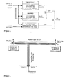
- a line current differential scheme comprises of two relays measuring the currents at both terminals of the protected line (or three relays for three terminal lines) through two sets of CTs, and of a communication channel that enables the relays to exchange the locally measured currents.
- I R I A + I B
- restraining signal is not important to the present discussion, as the disclosed embodiments will work with any suitably defined restraining signal.
- FIG. 2 depicts an exemplary two-slope characteristic. It should be noted, however, that the present invention is applicable with any differential characteristic including the one that uses a dynamic restraint as given by equation (2d).
- the differential current of equation (3) may be high enough as compared with the restraining current to cause the operation of the differential protection element. Distance supervision as described later can be applied to solve this problem.
- the current differential relay may be sensitive enough to see such faults, but preferably should not operate as the line does not need to be taken out of service in the case of a fault outside the line and the tapped transformer.
- a distance supervision as described later can be applied to solve this problem.
- a line distance protection element or a separate relay supervises operation of the line current differential element (the AND gate producing the operate signal, OP).
- reach of the line distance protection element is preferably set to achieve the following objectives :
- Suitable filtering can be implemented in conventional microprocessor-based distance relays to meet the requirement c) in conjunction with a) and b).
- FIG. 5 illustrates the distance supervision principle
- the restraining current regardless of the applied approach, would be close to the line load current in the healthy phases and close to the fault current in the faulted phases. In both the cases, the spurious differential signal is likely to be high enough to cause relay malfunction.
- the modified differential current calculated as (5) does not respond to any zero sequence currents during external faults.
- the differential currents in all three phases would be zero for any type of external fault.
- Equation (6) provides just an example. It should be noted that the calculation of the restraining signal from the phase currents after removing the zero sequence component works with any definition of the restraining signal.
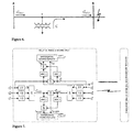
- the modified differential and restraining signals are created by the relay, they are subjected to the differential characteristic and the output operate flag, DIFF 2 , is created. As in the case of a traditional current differential technique, this is done on the per phase basis.
- the traditional characteristic, setting the flag DIFF 1 in FIG. 4 shows a tendency to overtrip on external ground faults, but is phase-selective on internal faults.
- the modified characteristic, setting the flag DIFF 2 in FIG. 4 shows a tendency to overtrip healthy phases on internal faults, but it is stable on external faults. Therefore the two characteristics should supervise each other mutually (the AND gate in FIG. 4 ).
- the resulting per-phase operands DIFF A , DIFF B and DIFF C retain both stability on external faults and phase-selectivity on internal faults. The latter enables proper identification of a faulted phase for the single-pole tripping mode.
- FIG. 7 depicts one possible implementation of the two differential characteristics.
- I DAEFFECTIVE min I DA ⁇ I DAMOD and than select the corresponding restraining current depending on the selection of the differential current.
Landscapes
- Emergency Protection Circuit Devices (AREA)
- Protection Of Transformers (AREA)
Applications Claiming Priority (2)
| Application Number | Priority Date | Filing Date | Title |
|---|---|---|---|
| US09/546,280 US6829544B1 (en) | 2000-04-10 | 2000-04-10 | Line current differential protective relaying method and relay for in-zone tapped transformers |
| EP01928441A EP1275184A2 (fr) | 2000-04-10 | 2001-04-10 | Procede ameliore de relais de protection differentielle de courant de ligne et relais ameliore pour transformateurs branches dans des zones |
Related Parent Applications (2)
| Application Number | Title | Priority Date | Filing Date |
|---|---|---|---|
| EP01928441.3 Division | 2001-04-10 | ||
| EP01928441A Division EP1275184A2 (fr) | 2000-04-10 | 2001-04-10 | Procede ameliore de relais de protection differentielle de courant de ligne et relais ameliore pour transformateurs branches dans des zones |
Publications (2)
| Publication Number | Publication Date |
|---|---|
| EP2175538A2 true EP2175538A2 (fr) | 2010-04-14 |
| EP2175538A3 EP2175538A3 (fr) | 2014-04-30 |
Family
ID=24179682
Family Applications (2)
| Application Number | Title | Priority Date | Filing Date |
|---|---|---|---|
| EP01928441A Withdrawn EP1275184A2 (fr) | 2000-04-10 | 2001-04-10 | Procede ameliore de relais de protection differentielle de courant de ligne et relais ameliore pour transformateurs branches dans des zones |
| EP10151004.8A Withdrawn EP2175538A3 (fr) | 2000-04-10 | 2001-04-10 | Procédé amélioré de relais de protection différentielle de courant de ligne et relais amélioré pour transformateurs branchés dans des zones. |
Family Applications Before (1)
| Application Number | Title | Priority Date | Filing Date |
|---|---|---|---|
| EP01928441A Withdrawn EP1275184A2 (fr) | 2000-04-10 | 2001-04-10 | Procede ameliore de relais de protection differentielle de courant de ligne et relais ameliore pour transformateurs branches dans des zones |
Country Status (5)
| Country | Link |
|---|---|
| US (1) | US6829544B1 (fr) |
| EP (2) | EP1275184A2 (fr) |
| AU (1) | AU2001255299A1 (fr) |
| MX (1) | MXPA01012753A (fr) |
| WO (1) | WO2001078209A2 (fr) |
Cited By (6)
| Publication number | Priority date | Publication date | Assignee | Title |
|---|---|---|---|---|
| CN103187719A (zh) * | 2013-01-31 | 2013-07-03 | 福建省电力有限公司 | 一种输电线路相间故障全分量电压保护方法 |
| CN103346539A (zh) * | 2013-07-04 | 2013-10-09 | 文杰 | 一种基于绝缘电阻测量的母线保护方法 |
| CN103500990A (zh) * | 2013-09-30 | 2014-01-08 | 国家电网公司 | 一种优化母差保护装置中母联ct绕组的选择方法 |
| CN103779845A (zh) * | 2014-02-14 | 2014-05-07 | 华北电网有限公司 | 一种提高串补线路电流差动保护动作性能的方法 |
| CN103986131A (zh) * | 2014-05-06 | 2014-08-13 | 国家电网公司 | 风电接入交直流混联电网的750kV线路保护系统 |
| CN104578009A (zh) * | 2015-01-19 | 2015-04-29 | 国家电网公司 | 一种换流器桥差保护防误动的方法 |
Families Citing this family (17)
| Publication number | Priority date | Publication date | Assignee | Title |
|---|---|---|---|---|
| SE518947C2 (sv) * | 2000-07-12 | 2002-12-10 | Abb Ab | Strömkompenseringsmetod och anordning för kraftsystemskydd |
| ES2372587T3 (es) | 2006-06-29 | 2012-01-24 | Abb Technology Ag | Relé de protección a distancia y método. |
| US7720619B2 (en) * | 2006-08-04 | 2010-05-18 | Schweitzer Engineering Laboratories, Inc. | Systems and methods for detecting high-impedance faults in a multi-grounded power distribution system |
| US8675327B2 (en) * | 2007-03-30 | 2014-03-18 | General Electric Company | Fast impedance protection technique immune to dynamic errors of capacitive voltage transformers |
| GB0713126D0 (en) * | 2007-07-06 | 2007-08-15 | Areva T & D Uk Ltd | Improvements in or relating to current differential protection relays |
| US8072715B2 (en) * | 2008-07-16 | 2011-12-06 | Huntington Ingalls Incorporated | Method, apparatus and computer program product for fault protection |
| CA2757750C (fr) * | 2009-04-09 | 2016-07-26 | Abb Schweiz Ag | Agencement d'echange d'energie |
| CN101800441B (zh) * | 2010-03-26 | 2012-03-28 | 河南省电力公司许昌供电公司 | 数字化变电站集中式保护装置边界信息缺失的处理方法 |
| CN102096024B (zh) * | 2010-12-17 | 2013-05-01 | 神华集团有限责任公司 | 一种查找电力系统中的直流接地故障的方法 |
| CN102629755B (zh) * | 2012-03-22 | 2014-12-03 | 中国电力科学研究院 | 一种基于广域信息的输电线路后备保护方法 |
| US10393810B2 (en) * | 2012-06-06 | 2019-08-27 | Abb Schweiz Ag | Method for identifying the fault by current differential protection and device thereof |
| CA2885185A1 (fr) | 2012-10-12 | 2014-04-17 | Schweitzer Engineering Laboratories, Inc. | Systemes et procedes de detection coordonnee d'un defaut d'impedance elevee |
| US20150078462A1 (en) * | 2013-07-18 | 2015-03-19 | GridEdge Networks, Inc. | Line current differential protection method and system using broadband power line carrier over high voltage transmission lines |
| CN106451369B (zh) * | 2015-08-13 | 2019-03-08 | 中国电力科学研究院 | 一种失灵保护中的截断电流互感器拖尾电流方法 |
| US10161986B2 (en) | 2016-10-17 | 2018-12-25 | Schweitzer Engineering Laboratories, Inc. | Electric power system monitoring using distributed conductor-mounted devices |
| CN113437733A (zh) * | 2021-08-30 | 2021-09-24 | 国网江西省电力有限公司电力科学研究院 | 基于综合阻抗的光伏发电并网联络线纵联保护方法及系统 |
| CN115224676B (zh) * | 2022-07-26 | 2026-02-03 | 西安热工研究院有限公司 | 小电阻接地系统站间联络线零序阻性电流差动保护方法 |
Citations (2)
| Publication number | Priority date | Publication date | Assignee | Title |
|---|---|---|---|---|
| US4715000A (en) | 1985-08-06 | 1987-12-22 | General Electric Company | Digital phase-locked loop and frequency measuring device |
| US5809045A (en) | 1996-09-13 | 1998-09-15 | General Electric Company | Digital current differential system |
Family Cites Families (4)
| Publication number | Priority date | Publication date | Assignee | Title |
|---|---|---|---|---|
| US5838525A (en) * | 1997-04-15 | 1998-11-17 | Abb Power T&D Company, Inc. | High speed single-pole trip logic for use in protective relaying |
| US5956220A (en) * | 1998-02-05 | 1999-09-21 | Abb Power T&D Company Inc. | Adaptive distance protection system |
| US6256592B1 (en) * | 1999-02-24 | 2001-07-03 | Schweitzer Engineering Laboratories, Inc. | Multi-ended fault location system |
| US6356421B1 (en) * | 1999-11-29 | 2002-03-12 | Schweitzer Engineering Labs., Inc. | System for power transformer differential protection |
-
2000
- 2000-04-10 US US09/546,280 patent/US6829544B1/en not_active Expired - Fee Related
-
2001
- 2001-04-10 EP EP01928441A patent/EP1275184A2/fr not_active Withdrawn
- 2001-04-10 AU AU2001255299A patent/AU2001255299A1/en not_active Abandoned
- 2001-04-10 WO PCT/US2001/011664 patent/WO2001078209A2/fr not_active Ceased
- 2001-04-10 EP EP10151004.8A patent/EP2175538A3/fr not_active Withdrawn
- 2001-04-10 MX MXPA01012753A patent/MXPA01012753A/es active IP Right Grant
Patent Citations (2)
| Publication number | Priority date | Publication date | Assignee | Title |
|---|---|---|---|---|
| US4715000A (en) | 1985-08-06 | 1987-12-22 | General Electric Company | Digital phase-locked loop and frequency measuring device |
| US5809045A (en) | 1996-09-13 | 1998-09-15 | General Electric Company | Digital current differential system |
Cited By (11)
| Publication number | Priority date | Publication date | Assignee | Title |
|---|---|---|---|---|
| CN103187719A (zh) * | 2013-01-31 | 2013-07-03 | 福建省电力有限公司 | 一种输电线路相间故障全分量电压保护方法 |
| CN103187719B (zh) * | 2013-01-31 | 2015-01-07 | 福建省电力有限公司 | 一种输电线路相间故障全分量电压保护方法 |
| CN103346539A (zh) * | 2013-07-04 | 2013-10-09 | 文杰 | 一种基于绝缘电阻测量的母线保护方法 |
| CN103346539B (zh) * | 2013-07-04 | 2016-05-11 | 南华大学 | 一种基于绝缘电阻测量的母线保护方法 |
| CN103500990A (zh) * | 2013-09-30 | 2014-01-08 | 国家电网公司 | 一种优化母差保护装置中母联ct绕组的选择方法 |
| CN103500990B (zh) * | 2013-09-30 | 2016-02-10 | 国家电网公司 | 一种优化母差保护装置中母联ct绕组的选择方法 |
| CN103779845A (zh) * | 2014-02-14 | 2014-05-07 | 华北电网有限公司 | 一种提高串补线路电流差动保护动作性能的方法 |
| CN103779845B (zh) * | 2014-02-14 | 2017-03-08 | 华北电网有限公司 | 一种提高串补线路电流差动保护动作性能的方法 |
| CN103986131A (zh) * | 2014-05-06 | 2014-08-13 | 国家电网公司 | 风电接入交直流混联电网的750kV线路保护系统 |
| CN103986131B (zh) * | 2014-05-06 | 2017-05-31 | 国家电网公司 | 风电接入交直流混联电网的750kV线路保护系统 |
| CN104578009A (zh) * | 2015-01-19 | 2015-04-29 | 国家电网公司 | 一种换流器桥差保护防误动的方法 |
Also Published As
| Publication number | Publication date |
|---|---|
| US6829544B1 (en) | 2004-12-07 |
| AU2001255299A1 (en) | 2001-10-23 |
| EP2175538A3 (fr) | 2014-04-30 |
| EP1275184A2 (fr) | 2003-01-15 |
| MXPA01012753A (es) | 2002-07-02 |
| WO2001078209A2 (fr) | 2001-10-18 |
| WO2001078209A3 (fr) | 2002-02-28 |
Similar Documents
| Publication | Publication Date | Title |
|---|---|---|
| US6829544B1 (en) | Line current differential protective relaying method and relay for in-zone tapped transformers | |
| US6839210B2 (en) | Bus total overcurrent system for a protective relay | |
| CN100388585C (zh) | 改进的故障保护电路及其方法 | |
| Esztergalyos-Chairman | Single phase tripping and auto reclosing of transmission lines IEEE committee report | |
| US8102634B2 (en) | Differential protection method, system and device | |
| US5838525A (en) | High speed single-pole trip logic for use in protective relaying | |
| EP1313194A2 (fr) | Protection de lignes d'énergie à double circuit | |
| US5566082A (en) | Method of detecting a fault section of busbar | |
| EP2328249B1 (fr) | Procédé de réenclenchement pour ligne de transport d'énergie électrique | |
| Bo et al. | Adaptive noncommunication protection of double-circuit line systems | |
| US3732464A (en) | Distance relay system | |
| CN102204050B (zh) | 差动保护方法和差动保护设备 | |
| Oppel et al. | Evaluation of the performance of line protection schemes on the NYSEG six phase transmission system | |
| US6501631B1 (en) | Method and device for power system protection | |
| Gajić et al. | Modern design principles for numerical busbar differential protection | |
| Kojovic | Rogowski coil performance characteristics for advanced relay protection | |
| Kasztenny et al. | Application of current differential protection to tapped transmission lines | |
| Kasztenny et al. | Digital low-impedance bus differential protection–Review of principles and approaches | |
| Kasztenny et al. | A new algorithm for digital low-impedance protection of busbars | |
| Horowitz | Transmission line protection | |
| Debrue et al. | Influence of distributed generation on the protection principles of a 70 kV/15 kV transformer in antenna: the zero-sequence over-voltage protection U0 | |
| Tang | Wide area differential protection system | |
| US20030107381A1 (en) | Method and device for power system protection | |
| EP1295374B1 (fr) | Procede et dispositif de protection d'un systeme generateur | |
| Sevov et al. | Considerations for differential protection in LV buses |
Legal Events
| Date | Code | Title | Description |
|---|---|---|---|
| PUAI | Public reference made under article 153(3) epc to a published international application that has entered the european phase |
Free format text: ORIGINAL CODE: 0009012 |
|
| AC | Divisional application: reference to earlier application |
Ref document number: 1275184 Country of ref document: EP Kind code of ref document: P |
|
| AK | Designated contracting states |
Kind code of ref document: A2 Designated state(s): AT BE CH CY DE DK ES FI FR GB GR IE IT LI LU MC NL PT SE TR |
|
| PUAL | Search report despatched |
Free format text: ORIGINAL CODE: 0009013 |
|
| AK | Designated contracting states |
Kind code of ref document: A3 Designated state(s): AT BE CH CY DE DK ES FI FR GB GR IE IT LI LU MC NL PT SE TR |
|
| RIC1 | Information provided on ipc code assigned before grant |
Ipc: H02H 3/40 20060101AFI20140321BHEP Ipc: H02H 7/22 20060101ALI20140321BHEP |
|
| STAA | Information on the status of an ep patent application or granted ep patent |
Free format text: STATUS: THE APPLICATION IS DEEMED TO BE WITHDRAWN |
|
| 18D | Application deemed to be withdrawn |
Effective date: 20141031 |