EP2175641B1 - Vorrichtung und Verfahren für Interpolation mit niedrigem Winkel - Google Patents
Vorrichtung und Verfahren für Interpolation mit niedrigem Winkel Download PDFInfo
- Publication number
- EP2175641B1 EP2175641B1 EP09004285A EP09004285A EP2175641B1 EP 2175641 B1 EP2175641 B1 EP 2175641B1 EP 09004285 A EP09004285 A EP 09004285A EP 09004285 A EP09004285 A EP 09004285A EP 2175641 B1 EP2175641 B1 EP 2175641B1
- Authority
- EP
- European Patent Office
- Prior art keywords
- angle
- interpolation
- pixels
- pixel
- scan line
- Prior art date
- Legal status (The legal status is an assumption and is not a legal conclusion. Google has not performed a legal analysis and makes no representation as to the accuracy of the status listed.)
- Not-in-force
Links
Images








Classifications
-
- H—ELECTRICITY
- H04—ELECTRIC COMMUNICATION TECHNIQUE
- H04N—PICTORIAL COMMUNICATION, e.g. TELEVISION
- H04N7/00—Television systems
- H04N7/01—Conversion of standards, e.g. involving analogue television standards or digital television standards processed at pixel level
- H04N7/0117—Conversion of standards, e.g. involving analogue television standards or digital television standards processed at pixel level involving conversion of the spatial resolution of the incoming video signal
- H04N7/012—Conversion between an interlaced and a progressive signal
-
- H—ELECTRICITY
- H04—ELECTRIC COMMUNICATION TECHNIQUE
- H04N—PICTORIAL COMMUNICATION, e.g. TELEVISION
- H04N7/00—Television systems
- H04N7/01—Conversion of standards, e.g. involving analogue television standards or digital television standards processed at pixel level
- H04N7/0135—Conversion of standards, e.g. involving analogue television standards or digital television standards processed at pixel level involving interpolation processes
- H04N7/0142—Conversion of standards, e.g. involving analogue television standards or digital television standards processed at pixel level involving interpolation processes the interpolation being edge adaptive
Definitions
- the invention relates to imaging processing technology, particularly to an apparatus and method of low angle interpolation.
- deinterlacing The process of converting interlaced video signals into progressive video signals is called deinterlacing.
- deinterlacing techniques including intra-field deinterlacing, inter-field deinterlacing, motion adaptive deinterlacing, motion compensated deinterlacing and so forth.
- the low angle interpolation method one of intra-field deinterlacing methods, is utilized to detect edges, find edge directions or edge angles and thereby perform interpolation along the edge directions.
- An edge dependent interpolation scheme is disclosed by Salonen J et al, "Edge adaptive interpolation for scanning rate conversions," signal processing of HDTV. proceedings of the international workshop on HDTV, xx, XX, vol. 4, 1 January 1993 (1993-01-01), pages 757-764 , XP000614509.
- the interpolation scheme uses direction information of nine directions in the conversion from interlaced normal definition picture to interlaced high definition picture (NHC). Detection of the edge orientation in the neighborhood of a target pixel is based on the absolute differences between pixel pairs on two successive lines, where each of nine directions corresponds to a sum of two absolute differences between two pixel pairs on two successive lines. A group possessing the lowest minimum response is found and stored as the main direction of the target pixel.
- a dominating main direction is looked for in a 5x3 neighborhood by assuming that edge direction information is consistent and unambiguous. In the case of ambiguous edge information, the vertical interpolation direction is preferred.
- a basic NHC operates in a 6x3 detector window in FIG. 4 .
- output samples are obtained using linear fixed interpolation in conjunction with 3-dimensional edge oriented median interpolation.
- a de-interlacing algorithm based on spatio-temporal weight and - edge direction is presented by Yong Ding et al. "A novel de-interlace based on spatio-temporal weight adaptive and edge-directed inperpolation," SIGNAL PROCESSING, the 8th international conference on, IEEE, PI, I January 2006(2006-01-01), XP031058554, ISBN: 9780780397361 .
- block matching criterion calculates the sum of absolute differences (SAD) by accumulating the absolute differences between a current 5x3 macro-block in current (t) field and the macro-block candidates in search window of t-2 field.
- the current 5x3 macro-block being in motion or static area is decided by comparing the SAD value with a motion threshold.
- a low-angle edge detection method uses the pixel-difference in 17x2 block size to determine the edge direction. The pixel-differences are calculated along the 17 diagonal directions which pass the target pixel. The minimal difference found will indicate is the direction of dominant edge. If the dominant edge direction shown in FIG. 2 is from X R to X L , the neighbor pixels X L-1 and X L+1 should be considered. The final edge direction can be detected by choosing the smallest difference among the difference between X R and X L , the one between X R and X L-1 , and the one between X R and X L+1 .
- EP Patent No. 0 550 231 presents an interpolation method, in which a new line is interpolated between the lines in a sampled TV picture using an edge detection.
- edge detection a 6x3 window is used to detect an edge in nine directions, excluding the horizontal direction. Each of the nine directions is examined by calculating the sum of the absolute differences of two pixel pairs.
- a 5x3 mask is formed by fifteen edge detection estimates. Each of the edge detection estimates comprises information of four parts: (1) the direction of the minimum response of group Ro; (2) the direction of the minimum response of group Rv; (3) the direction of the minimum response of group Rk; (4) TOTmin, which indicates which group has the lowest minimum response. Based on fifteen edge detection estimates, the final interpolation direction of the interpolated pixel is selected. Finally, a corresponding three-point median filter is selected to perform interpolation according to the final interpolation direction.
- EP Patent No. 0 687 104 presents a method for detecting and encoding edges in an interlaced video signal.
- edge detection a 6x3 window is used to detect an edge in ten directions, including the horizontal direction, for each examined sample X in FIGS. 4a-ai .
- Each of the ten directions, excluding the horizontal direction, is examined by calculating the sum of the absolute differences of two pixel pairs. A group possessing the lowest minimum response is found and stored as the main direction of the examined sample X.
- a 5x3 window is used to find a dominant direction by counting the number of main directions. The total number of active positions within the 5x3 window is calculated and half of the act count specifies the minimum amount required for a main direction to be a dominant direction.
- three successive positions in a line are considered to determine the required final interpolation direction for the position e8 in FIG. 9 . If the interpolation direction in the position e8 has been selected from either the left or the right main direction and if both e7 and e8 have been selected from the middle interpolation direction, then the selected direction in e8 is not consistent and the direction of the position e7 is used.
- US Publication No. 2005/163401 discloses a display image enhancement apparatus for use in generating additional pixel data from input image data, wherein a window of input pixel data is used to generate data for an additional pixel to be placed in the center of the window.
- the display image enhancement apparatus includes memory elements, an instant angle detection circuitry and a substantial angle detection circuitry.
- the memory elements are used to store at least the window of input pixel data which includes a plurality of pixel pairs each of which respectively represents an angle of correlation.
- the instant angle detection circuitry is selected to determine an instant angie having the highest correlation based on differential values of at least some of the pixel pairs.
- the substantial angle detection circuitry is selected to determine a substantial angle having the highest correlation based on filtered differential values of at least some of the pixel pairs.
- a combination of the differential values of eight or more of similarly oriented pixel pairs to the right and to the left of the window represents a given angle. This combination may be a simple sum, weighted sum or average.
- a combination having the smallest value is selected and the angle corresponding to that combination is determined as the substantial angle.
- US Publication No. 2008/0074538 discloses a de-interlacing method and apparatus using a direction map. For each of edge pixels in the to-be-de-interlaced field I, a corresponding edge direction value is determined. Then, judge whether each of the display pixels near a to-be-interpolated pixel has a corresponding edge direction value. Set an edge direction value for the to-be-interpolated pixel according to the result of comparing the number of the display pixels corresponding to the left down edge direction with the number of the display pixels corresponding to the right down edge direction among the display pixels near the to-be-interpolated pixel.
- a pixel pair in the display lines above and under the to-be-interpolated pixel is selected according to edge direction value of the to-be-interpolated pixel so that the luminance value and the chrominance value of the to-be-interpolated pixel is obtained.
- an edge direction is determined by calculating along more angles (with respect to a horizontal line) and the calculated angles tend to become gentler (getting close to the horizontal line).
- an edge detection method is subject to making mistakes.
- the distance between two pixels that are used to calculate a pixel difference is quite long.
- one objective of the invention is to provide an apparatus of low angle interpolation to calculate the sum of absolute differences (SAD) according to triangle-like counterclockwise operating and clockwise operating matrixes to thereby correctly detect edges and effectively reduce jaggies.
- the apparatus of low angle interpolation is used to generate an interpolation scan line between two adjacent known scan lines of a field.
- the apparatus comprises a low angle calculation circuit, a line buffer, a direction decision circuit, a post-processing circuit, and an interpolator.
- the low angle calculation circuit receives all luminance values of the two adjacent known scan lines, calculates and compares sums of absolute differences (SADs) of a plurality of angles for each pixel in the interpolation scan line and generating a plurality of operating parameters for each pixel in the interpolation scan line based on a counterclockwise operating matrix and a clockwise operating matrix.
- the line buffer stores final interpolation directions for all pixels of a preceding interpolation scan line.
- the direction decision circuit coupled to the line buffer and the low angle calculation circuit determines a temporary interpolation angle for each pixel in the interpolation scan line based on the operating parameters of each pixel in the interpolation scan line and the final interpolation directions of all the pixels of the preceding interpolation scan line.
- the post-processing circuit coupled to the line buffer and the direction decision circuit, performs calibration on temporary interpolation direction and determines a final interpolation angle and the final interpolation direction for each pixel in the interpolation scan line based on the temporary interpolation angles for all the pixels in the interpolation scan line and the final interpolation directions of all the pixels of the preceding-interpolation scan line.
- the interpolator coupled to the post-processing circuit receives the final interpolation angle for each pixel of the interpolation scan line, both the luminance values and chrominance values of all pixels in the two adjacent known scan lines, and performing interpolation corresponding to either the final interpolation angle or 90 degrees for each pixel in the interpolation scan line depending on a sum of absolute chrominance differences for specified pixel pairs selected from the two adjacent known scan lines so as to generate the luminance value and the chrominance value for each pixel in the interpolation scan line based on the counterclockwise operating matrix and the clockwise operating matrix; wherein each of the final interpolation angle and the temporary final interpolation angle comprises a corresponding interpolation direction; wherein each of the counterclockwise operating matrix and the clockwise operating matrix comprises a plurality of angle matrixes having different widths and each angle matrix comprises a pair of upper and lower matrixes having the same corresponding width and representing a corresponding angle with respect to a horizontal line; and, wherein the widths of the angle
- Another objective of the invention is to provide a method of low angle interpolation method, four generating an interpolation scan line between two adjacent known scan lines.
- the method comprises the following steps: calculating and comparing sums of the absolute differences (SADs) of a plurality of angles for each pixel in the interpolation scan line to obtain a plurality of operating parameters for each pixel in the interpolation scan line based on all luminance values of the two adjacent known scan lines, a counterclockwise operating matrix, and a clockwise operating matrix; determining a temporary interpolation angle for each pixel in the interpolation scan line, based on the operating parameters for each pixel in the interpolation scan line and the final interpolation directions for all the pixels of the preceding interpolation scan line; performing calibration on temporary interpolation directions based on the temporary interpolation angles for all the pixels in the interpolation scan line and the final interpolation directions for all the pixels of the preceding interpolation scan line to determine the final interpolation angle and the final interpolation direction for each
- FIG. 1 shows a schematic diagram illustrating the relationship between the original scan lines and missing scan lines during the deinterlacing process in a local area of a field.
- FIG. 2 shows a schematic diagram illustrating a low angle interpolation apparatus according to one embodiment of the invention.
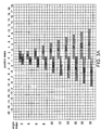
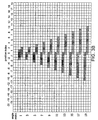
- FIG. 3A and FIG. 3B show the counterclockwise operating matrix and the clockwise operating matrix, respectively, according to one embodiment of the invention
- FIG. 4 shows a schematic diagram illustrating an exemplary portion of the scan lines L ( i -1) and L ( i +1) having mutually opposite luminance gradients.
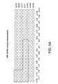
- FIG. 5A shows a schematic diagram illustrating an ideal image after a broken-angle compensation.
- FIG. 5B shows a schematic diagram illustrating an interpolated image without the broken- angle compensation.
- FIG. 5C shows a relationship between an angle-4 matrix and a to-be-interpolated pixel (p(i,n)), where five dashed-line rectangles are used to set broken-angle flags of pixels p(i-1, n+6), p(i-1, n+7), p(i-1, n+8), p(i+1, n-8) and p(i+1, n-9), respectively.
- FIG. 6 shows a schematic diagram illustrating the direction decision circuit according to one embodiment of the invention.
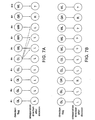
- FIG. 7A shows a schematic diagram illustrating that the clockwise effectiveness of the three consecutive pixels having GL can be extended to the following three consecutive pixels having WL or WR.
- FIG. 7B shows a schematic diagram illustrating that three consecutive pixels having GL cannot be found and thus the interpolation directions for the pixels having WL cannot be decided.
- FiG. 7C shows a schematic diagram illustrating that the clockwise effectiveness of a pixel having SL can be extended to the following three consecutive pixels having WL or WR.
- FIG. 7D shows a schematic diagram illustrating that the final interpolations dir_f for all the pixels of the preceding interpolation scan line L(i-2) stored in the line buffer 260 are used to determine the undecided interpolation directions of the pixels in the interpolation scan line L(i).
- FIG. 8 shows a schematic diagram illustrating the post-processing circuit according to one embodiment of the invention.
- FIG. 9 shows an example of a scene window having a pixel p(i,n) as the center and having a width of 21 points.
- FIG. 10A shows an example of a conflict window fitting an "LR" conflict pattern.
- FIG. 10B shows another example of the conflict window fitting an "LNR" conflict pattern.
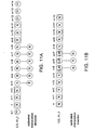
- FIG. 11A is an example illustrating that two groups of pixels having the interpolation direction R are isolated by a third group of pixels having the interpolation direction N.
- FIG. 11B is an example illustrating that two groups of pixels having the interpolation direction N are isolated by a third group of pixels having low angles.
- FIG. 12 shows an example of the adjusted interpolations D of a portion of pixels in the interpolation scan line L(i) .
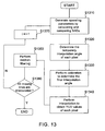
- FIG. 13 shows a flow chart of the low angle interpolation method according to the invention.
- the low angle interpolation apparatus may be hardware, software, or a combination of hardware and software (or firmware).
- An example of a pure solution would be a field programmable gate array (FPGA) design or an application specific integrated circuit (ASIC) design.
- An example of a hardware and software implementation would be a digital signal processor (DSP) and embedded firmware.
- FIG. 1 shows a schematic diagram illustrating the relationship between the original scan lines and missing scan lines during the deinterlacing process in a local area of a field.
- each circle represents a pixel and there are four rows of circles with solid lines showing the original scan lines (having Y, U, V components) while there are three rows of circles with dashed lines showing the missing scan lines to be interpolated in the field.
- FIG. 2 shows a schematic diagram illustrating a low angle interpolation apparatus according to one embodiment of the invention.
- the low angle interpolation apparatus 200 includes a low angle calculation circuit 210, a direction decision circuit 220, a post-processing circuit 230, an interpolation 240, an adaptive 5-point median filter 250 and a line buffer 260.
- the low angle interpolation apparatus 200 receives any two neighboring original scan lines (e.g., L(i - 1) and L(i + 1) in FIG.
- FIG. 3A and FIG. 3B show a counterclockwise operating matrix and a clockwise operating matrix, respectively, according to one embodiment of the invention.
- Each of horizontal axes in FIGS. 3A and 3B represents the pixel position index where a position index of 0 is aligned to a interpolation pixel (e.g., p(i,n) in FIG. 1 ) whose sum of absolute differences (SAD) with respect to each angle will be calculated in the interpolation scan line L(i).
- SAD sum of absolute differences
- FIGS. 3A and 3B there are 10 different angle index values on each of vertical axes. As the angle index value is getting less, the angle is closer to 90 degrees with respect to a horizontal line through the interpolation pixel p(i,n) .
- the angle index value further includes the interpolation direction information.
- the angle index values in FIG 3A are all even numbers, denoting the angle in a counterclockwise direction with respect to the horizontal line through the interpolation pixel (e.g., p(i,n) in FIG. 1 ).
- the angle index values in FIG. 3B are all odd numbers, denoting the angle in a clockwise direction with respect to a horizontal line through the interpolation pixel (e.g., p(i,n) in FIG. 1 ).
- the angle index value equals 0, the angle is 90 degrees.
- Each angle index value corresponds to an angle matrix and each angle matrix consists of a pair of upper and lower matrixes.
- a SAD of the interpolation pixel p(i,n) with respect to a specified angle is obtained by applying the corresponding pair of upper and lower matrixes to the upper scan line L(i-1) and the lower scan line L(i+1) respectively.
- the shapes of the counterclockwise operating matrix and the clockwise operating matrix look like triangles; besides, as the angle index value is larger, its corresponding upper matrix and lower matrix have wider widths and contain more reference pixels.
- each matrix has one dark point as the center.
- each matrix has two dark points as the center.
- FIGS. 3A and 3B are respectively divided into 10 different angles, but the invention is not limited to this specific arrangement. As long as the shapes of the counterclockwise operating matrix and the clockwise operating matrix resemble triangles, the slopes and the angle index values of the counterclockwise operating matrix and the clockwise operating matrix may be modified and practiced.
- the low angle calculation circuit 210 receives luminance values (expressed by L(i - 1)_Y and L(i + 1)_Y in FIG. 2 ) of all pixels of the two original neighboring scan lines L(i - 1) and L(i + 1) of the field 280. According to the counterclockwise operating matrix in FIG. 3A and the clockwise operating matrix in FIG. 3B , for every pixel in the interpolation scan line L(i) (from left to right, a total of 720 pixels), the 90-degree SAD sad_n, the SADs of ten different angles in the counterclockwise direction and the SADs of ten different angles in the clockwise direction are calculated in the low angle calculation circuit 210.
- the minimum counterclockwise SAD min_sad_r and its corresponding angle angle_r the minimum clockwise SAD min_sad_I and its corresponding angle angle_I, and the 90-degree SAD sad_n are obtained.
- the angles angle_r, angle_l, angle_lr, angle_t, and angle_f are expressed by the angle index value.
- the operation that low angle calculation circuit 210 generates the counterclockwise SAD sad_r and the 90-degree SAD sad_n will be described in detail in connection with the counterclockwise operating matrix in FIG. 3A .
- the angle-6 matrix comprises a pair of upper and lower matrixes with a width of 4.
- the upper matrix is applied to the pixels p(i - 1,n) ⁇ p(i - 1,n + 3) of the scan line L(i-1) while the lower matrix is applied to the pixels p(i + 1,n-3) ⁇ p(i + 1,n) of the scan line L(i + 1).
- the parameters w0, w1, and w2 can be adjusted according to the image contents.
- the low angle calculation circuit 210 uses three compensation units to compensate for the ten counterclockwise SADs sad_r(2) ⁇ sad_r(20), the ten clockwise SADs sad_l(1) ⁇ sad_l(19), and the 90-degree SAD sad_n and then compares the SAD values.
- the three compensation units (not shown) will be described below.
- the first one is a gradient compensation unit to be applied to the 90-degree SAD compensation.
- FIG. 4 shows a schematic diagram illustrating a exemplary portion of the scan lines L(i-1) and L(i+1) having mutually opposite luminance gradients.
- the scan lines L(i-1) and L(i+1) have mutually opposite luminance gradients (that is, the scan line L(i-1) have continuously decreasing luminance values and the scan line L(i+1) have continuously increasing luminance values from left to right) with similar luminance values around the pixel p(i,n).
- the sad_n value is usually small if the sad _ n value is obtained according to the equation (1).
- the direction decision circuit 220 likely selects the 90-degree direction as the temporary interpolation direction dir_t. After interpolation, the interpolated luminance of the pixel p(i,n) will be close to white and the edge in the counterclockwise direction looks like broken and discontinuous.
- the parameters w3 and w4 can be adjusted according to the image contents.
- the gradient compensation value sad_nc is obtained by calculating the sum of absolute luminance differences between the pixel pair in the horizontal direction and the pixel pair in vertical direction within a gradient window having a width of 5.
- the gradient compensation value sad_nc is used to compensate the sad_n value.
- the sad_nc value tends to be small, which will not badly affect the possibility that the direction decision circuit 220 selects the 90-degree direction.
- the sad_nc value is compared with a threshold value and the sad_nc value will be replaced with the threshold value if the sad_nc value is greater than the threshold value in order to avoid over-compensation. It should be noted that the width of the gradient window is adjustable depending on applications.
- the second compensation unit is a broken-angle compensation unit to be applied to the counterclockwise SAD compensation and the clockwise SAD compensation.
- FIG. 5A shows a schematic diagram illustrating an ideal image after a broken-angle compensation while FIG 5B shows a schematic diagram illustrating an interpolated image without the broken- angle compensation.
- the clockwise SADs sad_l are usually determined to be the minimum and then the pixels a, b, c , and d become white after interpolation, thereby forming a broken angle at the boundary of the L-shaped edge.
- FIG. 5A shows a schematic diagram illustrating an ideal image after a broken-angle compensation
- FIG. 5B shows a schematic diagram illustrating an interpolated image without the broken- angle compensation.
- 5C shows a relationship between an angle-4 matrix and a to-be-interpolated pixel (p(i,n)), where five dashed-line rectangles are used to set broken-angle flags of pixels p(i-1, n+6), p(i-1, n+7), p(i-1, n+8), p(i+1, n-8) and p(i+1, n-9), respectively.
- the absolute luminance differences between three vertical pixels of three scan lines as represented in the dashed-line rectangles in FIG. 5C . Take the pixel p(i-1, n+6) for example.
- the absolute luminance difference between pixels p(i-1, n+6) and p(i-3, n+6) and the absolute luminance difference between p(i-1, n+6) and p(i+1, n+6) are both smaller than a threshold value th1, i.e., abs(y(i-3,n+6)-y(i-1,n+6)) ⁇ th1 && abs(y(i-1,n+6)- y(i+1,n+6)) ⁇ th1.
- Ten counterclockwise sad_r values and ten clockwise sad_l values of each pixel in the interpolation scan line L(i) are calculated by using twenty sets of the upper matrix and the lower matrix with different widths. According to the invention, the more one set of the upper matrix and the lower matrix highly overlaps with the edge, the lower the possibility of a broken angle. Thus, it is necessary to evaluate the degree that the upper and lower matrixes overlap with either one end of the edge for each angle, that is, to accumulate the broken-angle flag values of all the pixels within the upper and lower matrixes for every angle to compensate the SAD of the corresponding angle. Regarding the example shown in FIG.
- the clockwise SADs sad _ l with respect to the pixels a, b, c and d should be compensated to avoid the above-mentioned broken-angle problem.
- the angle-4 matrix comprises a pair of the upper matrix and the lower matrix having a width of 3.
- the broken-angle flag values of p(i-1,n), p(i-1, n+1), and p(i-1, n+2) within the window of the upper matrix and the broken-angle flag values of p(i+1,n-2), p(i+1, n-1), and p(i+1, n) within the window of the lower matrix are accumulated to compensate the sad_r(4) value of the pixel p(i,n).
- the threshold value break_th1 is a function of angle index, meaning that different angles correspond to different sum of broken-angle flag values.
- the compensated value sad_c will be added to sad_r on condition that it is greater than the threshold value break_th1. Since the compensation for other angles except 90 degrees is made in the same manner, the detail will not be further described.
- the third compensation unit is a slope compensation unit to be applied to the SAD compensation for all the angles.
- the slope compensation is optional and applied in some specific cases. For example, if the counterclockwise operating matrix of FIG 3A and the clockwise operating matrix of FIG 3B have pre-set steep slopes or very gentle slopes and the slopes are implemented by hardware and hard to be altered, the slope compensation can be introduced. If the slopes of the counterclockwise and clockwise operating matrixes are very gentle (i.e., the widths of the upper matrix and the lower matrix are too wide), the low-angle edge seems not easy to be selected. At the time, an effect of inversely adjusting the slopes of the counterclockwise and clockwise operating matrixes can be achieved by modifying the SADs of each angle.
- the compensation value i.e., (10 - k ) ⁇ step, where step is a pre-set value and adjustable
- step is a pre-set value and adjustable
- the slopes of the clockwise operating matrix and the counterclockwise operating matrix become steeper (that is, the bottom of the triangle becomes narrow). Accordingly, the low angle is easier to be selected.
- another set of equations can be designed to have the compensation value be larger if the angle index value is larger to thereby achieve the effect of inversely adjusting the slopes of the clockwise operating matrix and the counterclockwise operating matrix and have the low angle be selected less easily.
- the low angle calculation circuit 210 compares ten different counterclockwise SADs sad_r to obtain the minimum counterclockwise SAD min_sad_r and its corresponding angle angle_r and compares ten different clockwise SADs sad_l to obtain the minimum counterclockwise SADs min_sad_l and its corresponding angle angle_l to thereby output min_sad_r, angle_r, min_sad_l, angle_l, and sad_n pixel by pixel to the direction decision circuit 220.
- the line buffer 260 is provided to store the final interpolation directions dir_f of aii the pixels of the preceding interpolation scan line L(i-2).
- two bits are provided for each pixel to denote one of three final interpolation directions: the angle in the counterclockwise direction, the angle in the clockwise direction, and the 90-degree direction.
- the size of the line buffer 260 has to be larger than or equal to 720x2 bits.
- FIG. 6 shows a schematic diagram of the direction decision circuit according to one embodiment of the invention.
- the direction decision circuit 220 comprises a left-right decision circuit 610 and a direction selecting circuit 620.
- temporary interpolation angles angle_t of all the pixels in the interpolation scan line L(i) are determined pixel by pixel according to min_sad_r, min_sad_l, angle_r angle_l , and sad n of all the pixels in the interpolation scan line L(i) and the final interpolation directions dir_f of all the pixels in the preceding interpolation scan line L(i-2) stored in the line buffer 260.
- the parameter big_dif is larger than the parameter normal_dif.
- the intensity order of the clockwise flags is SL>GL>WL and the intensity order of the counterclockwise flags is SR>GR>WR.
- the interpolation direction of a pixel can be directly determined to be clockwise if the intensity of its direction flag is beyond SL or GL; the interpolation direction of a pixel can be directly determined to be counterclockwise if the intensity of its direction flag is beyond SR or GR. If the intensity of the direction flag is WL or WR, the direction flag is relatively weak and thus the following three deciding units will be provided for determination.
- the interpolation directions of x consecutive pixels having GL affect the interpolation directions of the following y consecutive pixels having WL (or WR), where x and y are adjustable.
- three consecutive pixels (a3 ⁇ a5) having GL are found first and the interpolation directions of the pixels (a3 ⁇ a5) are directly determined to be clockwise (L).
- the effectiveness of the clockwise direction of the pixels (a3 ⁇ a5) is be extended to the following three consecutive pixels (a6 ⁇ a8) having WL or WR. As shown in FIGS.
- the question mark (?) represents that the interpolation direction is undecided.
- FIG. 7B three consecutive pixels having GL cannot be found and thus the interpolation directions of the pixels having WL or WR cannot be determined.
- the interpolation direction of one pixel having SL affects the interpolation directions of the following z consecutive pixels having WL (or WR) where z is adjustable.
- a pixel (b5) having SL is found first and the interpolation direction of the pixel (b5) is directly decided to be clockwise (L). Then, the effectiveness of the clockwise direction of the pixel (b5) is extended to the following three consecutive pixels (b6 ⁇ b8) having WL or WR.
- a preceding line auxiliary deciding unit 613 uses the final interpolation directions dir_f of all the pixels of the preceding interpolation scan line L(i-2) stored in the line buffer 260 to determine the interpolation direction of the pixel whose interpolation direction is still undecided.
- a pixel search is conducted along the angle ( min_angle_l ) in the clockwise direction, a pixel (c4) will be found and its interpolation direction is clockwise (L); besides, if a pixel search is conducted along the angle ( min_angle_r ) in the counterclockwise direction, a pixel (c11) will be found and its interpolation direction is also clockwise.
- the interpolation direction of the pixel (d6) is clockwise.
- a pixel (c5) if a pixel search is conducted along the angle in the clockwise direction, a pixel (c5) will be found and its interpolation direction is the 90-degree direction (N); besides, if a pixel search is conducted along the angle in the counterclockwise direction, a pixel (c12) will be found and its interpolation direction is clockwise.
- the left hand side and the right hand side are both wrong.
- the interpolation direction of the pixel (d7) will be set to the 90-degree direction (N).
- the interpolation direction of the pixel (d8) will be set to the 90-degree direction (N).
- the left-right decision circuit 610 selects min_sad_Ir and its angle angle_ Ir corresponding to the interpolation direction from the inputs min_sad_r, min_sad_I, angle_r, and angle_I to be delivered to the direction selecting circuit 620. Then, in the direction selecting circuit 620, min_sad_Ir and sad_n are compared pixel by pixel to select the minimum value as sad_t and store its corresponding angle angle_t.
- the direction selecting circuit 620 determines whether sad_t is larger than a predetermined value max_sad(angle_t) or not and then sets the temporary interpolation angle angle_t to 90 degrees if sad_t is larger than max_sad(angle_t) ,.
- the predetermined value max_sad(angle_t) is a function of angles (angle_t), where the max_sad value depends on the angle_t value.
- the GUGR auxiliary deciding unit 611, the SUSR auxiliary deciding unit 612 and the preceding line auxiliary deciding unit 613 operate and are arranged in an ascending sequence of their reference numbers.
- the GUGR auxiliary deciding unit 611 can be exchanged with and the SUSR auxiliary deciding unit 612.
- FIG. 8 shows a schematic diagram of the post-processing circuit according to one embodiment of the invention.
- the post-processing circuit 230 comprises a complicate scene analyzing unit 810, a conflict direction calibration unit 820, an angle expanding unit 830 and an angle excluding unit 840.
- the post-processing circuit 230 performs calibration on the interpolation direction and determines the final interpolation angle angle_f and the final interpolation direction dir_f for each pixel in the interpolation scan line L(i). As shown in FIG.
- the post-processing circuit 230 finally stores the final interpolation direction dir_f of each pixel of the interpolation scan line L(i) in the line buffer 260 and transmits the final interpolation angle angle_f of each pixel of the interpolation scan line L(i) to the interpolator 240.
- the complicate scene analyzing unit 810 receives the temporary interpolation angles angle_t of all the pixels in the interpolation scan line L(i) and the luminance values (Y) of all the pixels of the scan lines L(i-1) and L(i+1). According to the width of a scene window in FIG. 9 , by treating the pixel p(i,n) of the interpolation scan line L(i) as the center, the complicate scene analyzing unit 810 accumulates the absolute luminance differences of the scan lines L(i-1) and L(i+1) in the horizontal direction.
- the temporary interpolation angle angle_t of the pixel p(i,n) will be set to 90 degrees in the complicate scene analyzing unit 810.
- a YD value is obtained by calculating the sum of the absolute luminance differences between the pixel, its right neighbor and its left neighbor and then the minimum between the YD value and the threshold value th3 is selected for accumulation.
- the temporary interpolation angle angle_t of the pixel p(i,n) is set to 90 degrees.
- YD_sum is less than the threshold value th2
- a simple scene within the scene window is determined and thus the temporary interpolation angle angle_t of the pixel p(i,n) remains unchanged.
- the conflict direction calibration unit 820 receives the temporary interpolation angles angle_t of all the pixels in the interpolation scan line L(i) and the final interpolation directions dir_f of all the pixels in the preceding interpolation scan line L(i-2) to calibrate the pixels having the conflict interpolation directions in the interpolation scan line L(i).
- the interpolation directions of an interpolation scan line are hardly likely to be immediately changed from counterclockwise (R) to clockwise (L) (or from clockwise to counterclockwise), so the conflict interpolation directions includes six conflict patterns: LR, RL, LNR, RNL, LNNR, and RNNL.
- the interpolation directions of consecutive pixels fit one of the six conflict patterns, the interpolation directions need to be reconfirmed.
- the case in FIG. 10A describes the pixels fit an "LR" conflict pattern.
- the conflict direction calibration unit 820 After finding out the boundary between L and R along the interpolation scan line L(i), the conflict direction calibration unit 820 has the boundary as a center line, draws a symmetric conflict window, and thus confirms the interpolation directions of the pixels ( e4 ⁇ e9 ) within the conflict window.
- Two pixels f3 and f5 having direction flags of N are found if three pixel searches are conducted from the pixels e4, e5 and e6 along their temporary interpolation directions (L, clockwise).
- the temporary interpolation directions of the pixels e4 and e5 are wrong and thus should be changed to the 90-degree direction (N).
- N the 90-degree direction
- three pixel searches are conducted from the pixels e7 ⁇ e9 along their temporary interpolation directions (R, counterclockwise)
- three pixels f12 ⁇ f14, each having a direction flag of R, will be found.
- the temporary interpolation directions of the pixels e7 ⁇ e9 are obviously correct and thus remain unchanged.
- the conflict direction calibration unit 820 After finding out the "LNR" conflict pattern along the interpolation scan line L(i) , the conflict direction calibration unit 820 has the pixel h6 having a flag of N as a center, draws a symmetric conflict window, and thus confirms the interpolation directions of the pixels ( h4 ⁇ h8 ) within the conflict window.
- a pixel g3 having a direction flag of N is found if two pixel searches are conducted from the pixels h4 and h5 along their temporary interpolation directions (L, clockwise). The temporary interpolation directions of the pixels h4 and h5 are wrong and thus should be changed to the 90-degree direction (N).
- the angle expanding unit 830 compares the temporary interpolation angles angle_t of all the pixels of the interpolation scan line L(i). If two groups of pixels having the same interpolation direction (clockwise or counterclockwise) are isolated by a third group of pixels having the interpolation direction N, the angle expanding unit 830 will set the interpolation direction of the third group of pixels to the same interpolation direction as those of the other two groups of pixels. However, it is required that the interpolation angle differences between the other two groups of pixels having the same interpolation direction (clockwise or counterclockwise) are not big and there is a smooth area located between the third group of pixels without an edge. As shown in FIG.
- a first group of three pixels p(i,n) ⁇ p(i,n+2) having the interpolation direction R and a second group of three pixels p(i,n+9) ⁇ p(i,n+11 ) having the same interpolation direction R are isolated by a third group of pixels p(i,n+3) ⁇ p(i,n+8) having the interpolation direction N.
- the angle expanding unit 830 will perform calibration on the interpolation directions of the pixels p(i,n + 3) ⁇ p(i,n + 8) and set the interpolation directions of the pixels p(i,n + 3) ⁇ p(i,n + 8) to the counterclockwise direction (R).
- the interpolation angles of the pixels p(i,n + 3) ⁇ p(i,n + 8) are set to the average of two interpolation angles of the two pixels p(i,n + 2) and p(i,n + 9).
- angle_t(i,n + 2) a
- angle_t(i,n + 9) b
- the interpolation angles angle_t(i,n + 3) ⁇ angle_t(i,n + 8) of the pixels p(i,n + 3) ⁇ p(i,n + 8) will be set to (floor((a + b) / 4) ⁇ 2) , if they are in the clockwise directions.
- the interpolation angles angle_t(i,n + 3) ⁇ angle _ t(i,n + 8) will be set to (floor((a + b) / 4) ⁇ 2 + 1), if they are in the clockwise directions, where the function floor(c) returns the largest integer that is not greater than the argument (c).
- the angle excluding unit 840 is provided to calibrate some discrete pixels having low angles randomly that are distributed among other pixels having an interpolation angle of 90 degrees. As shown in FIG.
- a first group of pixels p(i,n) ⁇ p(i,n + 4) having the interpolation direction N and a second group of the pixels p(i,n + 8) ⁇ p(i,n + 12) having the interpolation direction N are isolated by a third group of the three consecutive pixels p(i,n + 5) ⁇ p(i,n + 7) having the interpolation direction other than N.
- the angle excluding unit 840 will perform calibration on the interpolation directions of the pixels p(i,n + 5) ⁇ p(i,n + 7) and set the interpolation directions of the pixels p(i,n + 5) ⁇ p(i,n + 7) to the 90-degree direction (N).
- the angle excluding unit 840 stores the calibrated interpolation direction of each pixel of the interpolation scan line L(i) as the final interpolation direction dir_f in the line buffer 260 and transmits the final interpolation angle angle_f of each pixel of the interpolation scan line L(i) to the interpolator 240.
- the complicate scene analyzing unit 810 the conflict direction calibration unit 820, the angle expanding unit 830 and the angle excluding unit 840 operate and are arranged in an ascending sequence of their reference numbers.
- the interpolator 240 receives the final interpolation angle anglo_f of each pixel of the interpolation scan line L(i), both the luminance values (Y) and chrominance values (U, V) of all the pixels in the scan line L(i-1), and both the luminance values (Y) and chrominance values (U, V) of all the pixels in the scan line L(i+1) (expressed by L(i-1)_YUV and L(i+1)_YUV in FIG. 2 ).
- the interpolator 240 calculates the absolute chrominance error chroma_error for each pixel of the interpolation scan line L(i).
- the absolute chrominance error chroma_error of a pixel is obtained by calculating the sum of the absolute chrominance differences between the dark point (or the dark points) in the upper matrix and that (or those) in the iower matrix corresponding to its final interpolation angle angle_f.
- the YUV interpolation is performed pixel by pixel according to the final interpolation angle angle_f in the interpolator 240.
- the interpolator 240 performs the 90-degree interpolation. Accordingly, the luminance, the chrominance, and an adjusted interpolation direction (expressed by L(i)_YUVD in FIG. 2 ) of each pixel in the interpolation scan line L(i) are obtained.
- the adaptive 5-point median filter 250 performs a median filtering operation on the pixel having discontinuous interpolation direction D in the interpolation scan line L(i) .
- FIG. 12 shows an example of the adjusted interpolation directions D of a portion of pixels in the interpolation scan line L(i) where three dashed-line rectangles show the adjusted interpolation directions D are discontinuous. For the left dashed-line rectangle in FIG.
- the adaptive 5-point median filter 250 performs a median filtering operation on the pixels p(i,n-1) , p(i,n), and p(i,n + 1) of the scan line L(i), the pixel p(i-1,n) of the scan line L(i-1) , and the pixel p(i + 1,n) of the scan line L(i + 1) and selects the Y, U, V values of one pixel having the luminance median as output from the above five pixels.
- the luminance value (Y) of the pixel p(i,n-1) is the median value of the five pixels and thus the Y, U, V values of the pixel p(i,n-1) is selected as the output of the pixel p(i,n).
- the adaptive 5-point median filter 250 performs a median filtering operation on the pixels p(i,n), p(i,n + 1), and p(i,n + 2) of the scan line L(i) , the pixel p(i-1,n + 1) of the scan line L(i-1) , and the pixel p(i + 1,n + 1) of the scan line L(i+1).
- the Y, U, V values of the pixel having the luminance median is selected as the output of the pixel p(i,n + 1) from the above five pixels. Therefore, for each dashed-line rectangle in FIG. 12 , the median filtering operation is performed twice to filter out noises so as to increase image quality.
- the low angle interpolation apparatus 200 completes all the interpolation operations and filtering operations related to the interpolation scan line L(i) . Then, the low angle interpolation apparatus 200 immediately receives next two neighboring scan lines L(i + 1) and L(i + 3) of the field 280 to generate the next interpolation scan line L(i + 2) and repeats the above steps until all the missing scan lines in the field 280 are interpolated.
- FIG. 13 shows a flow chart of the low angle interpolation method according to the invention.
- the low angle interpolation method according to the invention will be described in detail according to FIG. 2 , FIG. 3A , FIG. 3B and FIG 13 .
- Step S1310 Calculate and compare the SADs of different angles related to each pixel in the interpolation scan line L(i) of the field 280 to generate a plurality of operating parameters for each pixel in the interpolation scan line L(i).
- the counterclockwise operating matrix in FIG. 3A and the clockwise operating matrix in FIG. 3B the 90-degree SAD sad_n , the ten different counterclockwise SADs and the ten different clockwise SADs of each pixel in the interpolation scan line L(i) are calculated.
- the minimum counterclockwise SAD min_sad_r and its corresponding angle angle_r the minimum counterclockwise SADs min_sad_I and its corresponding angle angle_I, and the 90-degree SAD sad_n.
- Step S1320 Determine the temporary interpolation angles angle_t of all the pixels in the interpolation scan line L(i), according to the operating parameters of each pixel in the interpolation scan line L(i) and the final interpolation directions dir_f of all the pixels of the preceding interpolation scan line L(i-2) .
- the temporary interpolation angle angle_t of each pixel in the interpolation scan line L(i) are determined pixel by pixel.
- Step S1330 Perform calibration on the interpolation directions to determine the final interpolation angle angle_f and the final interpolation direction dir_f of each pixel in the interpolation scan line L(i) based on the temporary interpolation angles angle_t of all the pixels in the interpolation scan line L(i) and the final interpolation directions dir_f of all the pixels in the preceding interpolation scan line L(i-2),.
- Step S1340 Perform interpolation to obtain the luminance value (Y) and the chrominance value (U,V) of each pixel in the interpolation scan line L(i).
- the final interpolation angle angle_f of each pixel in the interpolation scan line L(i), the luminance values (Y) and the chrominance values (U,V) of all the pixels in the scan line L(i-1), and the luminance values (Y) and the chrominance values (U,V) of all the pixels in the scan line L(i+1) are provided.
- the absolute chrominance error chroma_error is calculated. If the absolute chrominance error chroma_error of one pixel is not greater than a predetermined value th4, the interpolation corresponding to its final interpolation angle_f is performed.
- the absolute chrominance error chroma_error of the pixel is greater than the predetermined value th4, the 90-degree interpolation is performed.
- the luminance value (Y), the chrominance values (U,V), and the adjusted interpolation direction D are obtained pixel by pixel with respect to the interpolation scan line L(i).
- Step S1350 Perform median filtering operations on the pixels having discontinuous final interpolation directions along the interpolation scan line L(i). It should be noted that this step is optional according to the invention; however, this step achieves a positive effect of filtering out noises and enhancing the image quality.
- Step S1360 Determine whether all the missing scan lines are interpolated in this field 280 or not. If YES, the flow goes to the step S1370; otherwise, the flow is completed.
- FIG. 13 disclosed above is illustrative only, and it will be understood that many modifications may be made.
Landscapes
- Engineering & Computer Science (AREA)
- Computer Graphics (AREA)
- Multimedia (AREA)
- Signal Processing (AREA)
- Television Systems (AREA)
- Image Processing (AREA)
Claims (13)
- Vorrichtung für eine Interpolation mit niedrigem Winkel, angepasst eine Interpolationsabtastlinie (L(i)) zwischen zwei benachbarten bekannten Abtastlinien (L(i-1), L(i+1)) eines Feldes zu erzeugen, worin die Vorrichtung umfasst:eine Berechnungsschaltung (210) für einen niedrigen Winkel, die angepasst ist alle Luminanzwerte der zwei benachbarten bekannten Abtastlinien (L(i-1), L(i+1)) aufzunehmen, um erste Summen der absoluten Luminanzunterschiede (SADs) für mehrere Winkel für jeden Pixel in der Interpolationsabtastlinie (L(i)) zu berechnen und zu vergleichen und um mehrere Betriebsparameter für jeden Pixel in der Interpolationsabtastlinie (L(i)) zu erzeugen, worin die ersten Summen von absoluten Luminanzunterschieden (SADs) zwischen Pixelpaaren berechnet werden, die basierend auf einer linksdrehenden Arbeitsmatrix (Figur 3A) und einer im rechtsdrehenden Arbeitsmatrix (Figur 3B) unter den zwei bekannten Abtastlinien ausgewählt werden, und worin die Betriebsparameter eine Minimalsumme von linksdrehenden absoluten Unterschieden (min_sad_r) umfassen, einen ersten Winkel in einer linksdrehenden Richtung (Winkel_r), der der Minimalsumme der linksdrehenden absoluten Unterschiede entspricht, eine Minimalsumme von rechtsdrehenden absoluten Unterschieden (min_sad_l), einen zweiten Winkel in rechtsdrehender Richtung (Winkel_l), der der Minimalsumme von rechtsdrehenden absoluten Unterschieden entspricht, und eine Summe von 90 Grad absoluter Unterschiede (sad_n),einen Zeilenpuffer (260), der angepasst ist abschließende Interpolationsrichtungen (dir_f) für alle Pixel einer vorangegangenen Interpolationsabtastlinie (L(i-2)) zu speichern,eine Richtungsentscheidungsschaltung (220), die an den Zeilenpuffer (260) und an die Berechnungsschaltung (210) für einen niedrigen Winkel gekoppelt ist, die angepasst ist einen temporären Interpolationswinkel (Winkel_t) für jedes Pixel in der Interpolationsabtastlinie (L(i)) zu bestimmen, basierend auf den Betriebsparametern von jedem Pixel in der Interpolationsabtastlinie (L(i)) und den abschließenden Interpolationsrichtungen (dir_f) aller Pixel der vorangegangenen Interpolationsabtastlinie (L(i-2)),eine nachbearbeitende Schaltung (230), die an den Zeilenpuffer (260) und die Richtungsentscheidungsschaltung (220) gekoppelt ist, die angepasst ist eine Kalibrierung an temporären Interpolationsrichtungen (dir_f) auszuführen und basierend auf den temporären Interpolationswinkeln (Winkel_t) für alle die Pixel in der Interpolationsabtastlinie (L(i)) und den abschließenden Interpolationsrichtungen (dir_f) für alle die Pixel der vorangehenden Interpolationsabtastlinie (L(i-2)) einen abschließenden Interpolationswinkel (Winkel_f) und die abschließende Interpolationsrichtung (dir_f) für jeden Pixel in der Interpolationsabtastlinie (L(i)) zu bestimmen, undeinen Interpolator (240), der an die nachbearbeitende Schaltung (230) gekoppelt ist, der angepasst ist den abschließenden Interpolationswinkel (Winkel_f) für jedes Pixel der Interpolationsabtastlinie (L(i)), und sowohl die Luminanzwerte (Y) als auch die Chrominanzwerte (UV) aller Pixel in den zwei benachbarten bekannten Abtastlinien (L(i-1), L(i+1)) zu empfangen, um eine angeglichene Interpolationsrichtung (D) der Richtung einzustellen, die dem abschließenden Interpolationswinkel (Winkel_f) oder 90 Grad entspricht in Abhängigkeit von einer Summe absoluter Chrominanzunterschiede (chroma_fehler) für spezifizierte Pixelpaare, die unter den zwei benachbarten bekannten Abtastlinien (L(i-1), L(i+1)) ausgewählt sind, die dem abschließenden Interpolationswinkel (Winkel_f) entspricht, und um eine Interpolation der Luminanzwerte (Y) und der Chrominanzwerte (UV) für jedes Pixel in der Interpolationsabtastlinie (L(i)), basierend auf der abgeglichenen Interpolationsrichtung (D) durchzuführen,worin jeder des abschließenden Interpolationswinkels (Winkel_f) und des temporären abschließenden Interpolationswinkels (Winkel_t) eine entsprechende Interpolationsrichtung (dir_f oder dir_t) umfasst,worin jede der linksdrehenden Betriebsmatrix (Figur 3A) und der rechtsdrehenden Betriebsmatrix (Figur 3B) mehrere Winkelmatrices umfasst, die unterschiedliche Weiten aufweisen und worin jede Winkelmatrix ein Paar oberer und unterer Matrices umfasst, die die gleichen entsprechenden Weiten aufweisen und einen Korrespondenzwinkel bezüglich einer horizontalen Linie darstellen, undworin sich die Weiten der Winkelmatrices erhöhen, wenn sich der Winkel in jeder der linksdrehenden Betriebsmatrix (Figur 3A) und der rechtsdrehenden Betriebsmatrix (Figur 3B) verringert.
- Vorrichtung nach Anspruch 1 weiter umfassend:einen Medianfilter (250), der angepasst ist einen Mittenfiltervorgang an den Luminanzwerten und den Chrominanzwerten der Pixel auszuführen, die diskontinuierliche angepasste Interpolationsrichtungen (D) in der Interpolationsabtastlinie (L(i)) aufweisen.
- Vorrichtung nach Anspruch 1, worin die Berechnungsschaltung (210) für einen niedrigen Winkel umfasst:eine Gradientenkompensationseinheit, die angepasst ist die Summe der 90 Grad absoluten Unterschiede (sad_n) für jedes Pixel der Interpolationsabtastlinie gemäß einer zweiten Summe von absoluten Luminanzunterschieden (sad_nc) unter spezifizierten Pixelpaaren zu kompensieren, die ausgewählt sind unter den zwei benachbarten bekannten Abtastlinien (L(i-1), L(i+1)) innerhalb eines 3*m Fensters (Figur 4), worin ein zu interpolierendes Pixel (p(i, n)) in der Mitte des 3*m Fensters lokalisiert ist und die zweite Summe von absoluten Luminanzunterschieden (sad_nc) unter spezifizierten Pixelpaaren, die unter den zwei benachbarten bekannten Abtastlinien innerhalb des 3*m Fensters ausgewählt wird, wie folgt berechnet wird:

 worin y(i-1, n+j), y(i-1, n+j+1), y(i+1, n+j) beziehungsweise y(i+1, n+j+1) die Luminanzwerte von Pixeln p(i-1, n+j), p(i-1, n+j+1), p(i+1, n+j) und p(i+1, n+j+1) darstellen und die Parameter m und Wj einstellbar sind, undeine Kompensationseinheit für Brechungswinkel, die angepasst ist für r Summen von rechtsdrehenden absoluten Unterschieden (sad_l) und r Summen von linksdrehenden absoluten Unterschieden (sad_r) für jedes Pixel der Interpolationsabtastlinie L(i) durch jeweiliges Berechnen der Grade zu kompensieren, dass die entsprechenden oberen und unteren Matrices mit einer Kante für 2*r Winkelmatrices überlappen, die 2*r unterschiedliche Winkel darstellen,worin jede der linksdrehenden Betriebsmatrix (Figur 3A) und der rechtsdrehden Betriebsmatrix (Figur 3B) r Winkelmatrices umfasst, worin r eine positive ganze Zahl ist.
 - Vorrichtung nach Anspruch 3, worin die Berechnungsschaltung für einen niedrigen Winkel (210) weiterhin eine Neigungskompensationseinheit umfasst, die angepasst ist die erste Summe der absoluten Luminanzunterschiede (SAD) für jeden Winkel für jedes Pixel der Interpolationsabtastlinie (L(i)) mit einem entsprechenden bestimmten Kompensationswert zu kompensieren und worin der entsprechende bestimmte Kompensationswert entweder proportional oder umgekehrt proportional zu dem entsprechenden Winkel ist.
- Vorrichtung nach Anspruch 1, worin die Richtungsentscheidungsschaltung (220) umfasst:eine Links-Rechts Entscheidungsschaltung (610), die angepasst ist eine Minimalsumme der absoluten Unterschiede (min_sad_lr) und einen anfänglichen Interpolationswinkel (Winkel_lr) zu bestimmen, der der Minimalsumme der absoluten Unterschiede für jedes Pixel in der Interpolationsabtastlinie (L(i)) gemäß der Minimalsumme von linksdrehenden absoluten Unterschieden (min_sad_r), dem ersten Winkel in der linksdrehenden Richtung (Winkel_r), der Minimalsumme von rechtsdrehenden absoluten Unterschieden (min_sad_l), und dem zweiten Winkel in der rechtsdrehenden Richtung (min_sad_l) für jedes Pixel in der Interpolationsabtastlinie (L(i)), und den abschließenden Interpolationsrichtungen (dir_f) für alle die Pixel in der vorangegangen Interpolationsabtastlinie (L(i-2)) entspricht, undeine Richtungswahlschaltung (620), die angepasst ist den temporären Interpolationswinkel (Winkel_t) gemäß des anfänglichen Interpolationswinkels (Winkel_lr), die Minimalsumme der absoluten Unterschiede (min_sad_lr), die sich auf den anfänglichen Interpolationswinkel beziehen, und die Summe von 90 Grad absoluten Unterschiede (sad_n) für jedes Pixel in der Interpolationsabtastlinie (L(i)) zu bestimmen.
- Vorrichtung nach Anspruch 5, worin die Links-Rechts Entscheidungsschaltung (610) eine Richtungsmarkierung für jedes Pixel in der Interpolationsabtastlinie (L(i)) gemäß der Minimalsumme von linksdrehenden absoluten Unterschieden (min_sad_r) und der Minimalsumme von rechtsdrehenden absoluten Unterschieden (min_sad_l) zuordnet,
worin die Richtungsmarkierung ausgewählt ist aus der Gruppe bestehend aus einer rechtsdrehenden starken Markierung, einer rechtsdrehenden schwachen Markierung, einer linksdrehenden starken Markierung, und einer linksdrehenden schwachen Markierung,
worin die Links-Rechts Entscheidungsschaltung (610) den anfänglichen Interpolationswinkel (Winkel_lr) eine zu interpolierenden Pixels (p(i,n)) auf den ersten Winkel in der linksdrehenden Richtung (Winkel_r) einstellt, falls das zu interpolierende Pixel die linksdrehende starke Markierung aufweist und den anfänglichen Interpolationswinkel (Winkel_lr) des zu interpolierenden Pixels auf den zweiten Winkel in der rechtsdrehenden Richtung (Winkel_l) einstellt, falls das einzustellende Pixel die rechtsdrehende starke Markierung aufweist, worin die Links-Rechts Entscheidungsschaltung (610) umfasst:eine erste Zusatzentscheidungseinheit (611, 612), die an die Berechnungsschaltung (210) für einen niedrigen Winkel gekoppelt ist, die angepasst ist die anfänglichen Interpolationswinkel (Winkel_lr) von y konsekutiv zu interpolierenden Pixeln, die entweder die rechtsdrehende schwache Markierung oder die linksdrehende schwache Markierung aufweisen, auf den zweiten Winkel in der rechtsdrehenden Richtung (winkel_l) einzustellen, falls die Interpolationsabtastlinie entlang einer spezifizierten Richtung bearbeitet wird und x konsekutiv zu interpolierenden Pixel gefunden werden, die die rechtsdrehende starke Markierung aufweisen gefolgt durch die y konsekutiv zu interpolierenden Pixel, die entweder eine rechtsdrehende schwache Markierung oder die linksdrehende schwache Markierung aufweisen, auf den ersten Winkel in der linksdrehenden Richtung (Winkel_r) einzustellen falls die Interpolationsabtastlinie entlang der spezifizierten Richtung bearbeitet wird und x konsekutiv zu interpolierende Pixel, die die linksdrehende starke Markierung aufweisen, gefolgt durch die y konsekutiv zu interpolierenden Pixel dort gefunden werden, wo x und y positive ganze Zahlen sind und abgeglichen werden können, undeine zweite Zusatzentscheidungseinheit (613), die an die erste Zusatzentscheidungseinheit (611, 612) und den Zeilenpuffer (260) gekoppelt ist, die angepasst ist den anfänglichen Interpolationswinkel (Winkel_lr) des zu interpolierenden Pixels, das entweder die linksdrehende schwache Markierung oder sie rechtsdrehende schwache Markierung aufweist, auf einen von einem 90 Grad Winkel, dem ersten Winkel in einer linksdrehenden Richtung (Winkel_r) und dem zweiten Winkel in einer rechtsdrehenden Richtung (Winkel_l) gemäß den abschließenden Interpolationsrichtungen (dir_f) für alle die Pixel in der vorangegangenen Interpolationsabtastlinie (L(i-2)) einzustellen. - Vorrichtung nach Anspruch 1, worin die nacharbeitende Schaltung (230) umfasst:eine Analyseeinheit für eine komplexe Szene (810), die angepasst ist den abschließenden Interpolationswinkel (winkel_f) eines zu interpolierenden Pixels (p(i,n)) auf den 90 Grad Winkel einzustellen, falls eine dritte Summe der absoluten Luminanzunterschiede (YD_Summe) unter spezifizierten Pixelpaaren, die unter den zwei benachbarten bekannten Abtastlinien (L(i-1), L(i+1)) innerhalb eines 3*m Fensters (Figur 9) ausgewählt sind, größer als ein Szenenschwellenwert ist, worin die dritte Summe von absoluten Luminanzunterschieden (YD_Summe) wie folgt berechnet wird:
 worin y(i-1,n+j), y(i-1,n+j-1), y(i-1,n+j+1), y(i+1,n+j), y(i+1,n+j-1) beziehungsweise y(i+1,n+j+1) die Luminanzwerte der Pixel p(i-1,n+j), p(i-1,n+j-1), p(i-1,n+j+1), p(i+1,n+j), p(i+1,n+j-1) und p(i+1,n+j+1) darstellen, worin die Parameter m und th3 eingestellt werden können,eine Konfliktrichtungskalibrierungseinheit (820), die angepasst ist die abschließenden Interpolationswinkel (Winkel_f) von mindestens zwei zu interpolierenden Pixeln zu bestimmen, die ihre temporären Interpolationsrichtungen (dir_t) aufweisen, die zu einem spezifischen Konfliktrichtungsmuster innerhalb eines 1*z Fensters (Figur 10A oder 10B) in der Interpolationsabtastlinie gemäß der abschließenden Interpolationsrichtungen (dir_f) für alle die Pixel der vorangegangenen Interpolationsabtastlinie (L(i-2)) passen, worin z eine ganze Zahl größer als 1 ist,eine Winkelerweiterungsschaltung (830), die angepasst ist die abschließende Interpolationsrichtung (dir_f) einer dritten Gruppe von Pixeln, die eine 90 Grad Interpolationsrichtung aufweisen auf eine erste Interpolationsrichtung einzustellen, falls eine erste Gruppe von Pixeln und eine zweite Gruppe von Pixeln, die eine erste Interpolationsrichtung aufweisen, durch eine dritte Gruppe von Pixeln in der Interpolationsabtastlinie isoliert wird, worin die erste Interpolationsrichtung entweder linksdrehend oder rechtsdrehend ist und worin Unterschiede zwischen den abschließenden Interpolationswinkeln (Winkel_f) der ersten Gruppe von Pixeln und den abschließenden Interpolationswinkeln (Winkel_f) der zweiten Gruppe von Pixeln kleiner als ein erster bestimmter Winkel sind und worin die dritte Gruppe von Pixeln gleichmäßig ist, undeine Winkelausschlussschaltung (840), die angepasst ist den abschließednen Interpolationswinkel (Winkel_f) einer sechsten Gruppe von Pixeln auf 90 Grad einzustellen, falls eine vierte Gruppe von Pixeln und eine fünfte Gruppe von Pixeln, die einen 90 Grad Interpolationswinkel aufweisen, durch die sechste Gruppe von Pixeln in der Interpolationsabtastlinie isoliert wird, worin die sechste Gruppe von Pixeln die temporären Interpolationswinkel (Winkel_t) aufweist, die kleiner als ein zweiter bestimmter Winkel sind,worin das spezifische Konfliktrichtungsmuster ausgewählt ist aus der Gruppe bestehend aus LR, RL, LNR, RNL, LNNR und RNNL, worin L, N beziehungsweise R eine rechtsdrehende Richtung, eine 90 Grad Richtung und eine linksdrehende Richtung darstellen.
 - Interpolationsverfahren mit niedrigem Winkel zum Erzeugen einer Interpolationsabtastlinie (L(i)) zwischen zwei benachbarten bekannten Abtastlinien (L(i-1), L(i+1)) eines Feldes, das Verfahren umfasst die folgenden Schritte:Berechnen und Vergleichen erster Summen von absoluten Luminanzunterschieden (SADs) für mehrere Winkel für jedes Pixel in der Interpolationsabtastlinie (L(i)), wobei die ersten Summen von absoluten Luminanzunterschieden (SADs) zwischen Pixelpaaren ausgewählt unter den zwei bekannten Abtastlinien berechnet werden, basierend auf einer linksdrehenden Betriebsmatrix (Figur 3A) und einer rechtsdrehenden Betriebsmatrix (Figur 3B),Erzeugen mehrerer Betriebsparameter für jedes Pixel in der Interpolationsabtastlinie (L(i)), wobei die Betriebsparameter eine Minimalsumme von linksdrehenden absoluten Unterschieden (min_sad_r) umfassen, einen ersten Winkel in einer linksdrehenden Richtung (Winkel_r), der der Minimalsumme der linksdrehenden absoluten Unterschiede entspricht, eine Minimalsumme von rechtsdrehenden absoluten Unterschieden (min_sad_l), einen zweiten Winkel in einer rechtsdrehenden Richtung (Winkel_l), der der Minimalsumme von rechtsdrehenden absoluten Unterschieden entspricht, und eine Summe von 90 Grad absoluten Unterschieden (sad_n),Bestimmen eines temporären Interpolationswinkels (Winkel_t) für jedes Pixel in der Interpolationsabtastlinie (L(i)), basierend auf den Betriebsparametern für jedes Pixel in der Interpolationsabtastlinie (L(i)) und den abschließenden Interpolationsrichtungen (dir_f) für alle Pixel einer vorangegangenen Interpolationsabtastlinie (L(i-2)),Durchführen einer Kalibrierung an temporären Interpolationsrichtungen (dir_t), basierend auf den temporären Interpolationswinkeln (Winkel_t) für alle die Pixel in der Interpolationsabtastlinie (L(i)) und den abschließenden Interpolationsrichtungen (dir_f) für alle die Pixel der vorangegangenen Interpolationsabtastlinie (L(i-2)), um einen abschliessenden Interpolationswinkel (Winkel_f) und die abschließende Interpolationsrichtung (dir_f) für jedes Pixel in der Interpolationsabtastlinie (L(i)) zu bestimmen, undEinstellen einer abgeglichenen Interpolationsrichtung (D) auf die Richtung, die dem abschließenden Interpolationswinkel (Winkel_f) entspricht oder auf 90 Grad, abhängig von einer Summe absoluter Chrominanzunterschiede (chroma_fehler) für spezifizierte Pixelpaare, die unter den zwei benachbarten bekannten Abtastlinien (L(i-1), L(i+1)) ausgewählt sind, was dem abschließenden Interpolationswinkel (Winkel_f) entspricht;Durchführen einer Interpolation der Luminanzwerte (Y) und der Chrominanzwerte (UV) für jedes Pixel in der Interpolationsabtastlinie (L(i)), basierend auf der abgeglichenen Interpolationsrichtung (D),wobei jeder des abschließenden Interpolationswinkels (Winkel_f) und des temporären abschließenden Interpolationswinkels (Winkel_t) eine entsprechende Interpolationsrichtung (dir_f oder dir_t) umfasst,wobei jede der linksdrehenden Betriebsmatrix (Figur 3A) und der rechtsdrehenden Betriebsmatrix (Figur 3B) mehrere Winkelmatrices umfasst, die unterschiedliche Weiten aufweisen, und wobei jede Winkelmatrix ein Paar oberer und unterer Matrices umfasst, die die gleiche entsprechende Weite aufweisen, und einen entsprechenden Winkel bezüglich einer horizontalen Linie darstellen, undwobei die Weiten der Winkelmatrices zunehmen, wie die Winkel in jeder der linksdrehenden Betriebsmatrix (Figur 3A) und der rechtsdrehenden Betriebsmatrix (Figur 3B) abnehmen.
- Verfahren nach Anspruch 8, wobei der Schritt eines Durchführens einer Interpolation weiterhin umfasst
Durchführen eines Medianfiltervorgangs auf die Luminanzwerte und die Chrominanzwerte der Pixel, die diskontinuierlich abgeglichene Interpolationsrichtungen (D) in der Interpolationsabtastlinie (L(i)) aufweisen. - Verfahren nach Anspruch 8, wobei der Schritt eines Berechnens und Vergleichens umfasst:Kompensieren der Summe von 90 Grad absoluter Unterschiede (SAD_n) für jedes Pixel der Interpolationsabtastlinie (L(i)) gemäß einer zweiten Summe von absoluten Luminanzunterschieden (SAD_nc) unter spezifizierten Pixelpaaren, die von den zwei benachbarten bekannten Abtastlinien (L(i-1), L(i+1)) innerhalb eines 3*m Fensters ausgewählt werden, wobei ein zu interpolierendes Pixel (p(i,n)) in der Mitte des 3*m Fensters lokalisiert ist und wobei die zweite Summe von absoluten Luminanzunterschieden (SAD_nc) unter spezifizierten Pixelpaaren, die unter den zwei benachbarten bekannten Abtastlinien innerhalb des 3*m Fensters ausgewählt werden, wie folgt berechnet wird
 worin y(i-1,n+j), y(i-1, n+j+1), y(i+1, n+j) beziehungsweise y(i+1, n+j+1) die Luminanzwerte von Pixeln p(i-1, n+j), p(i-1, n+j+1), p(i+1, n+j) und p(i+1, n+j+1) darstellen und die Parameter m und Wj einstellbar sind, undKompensieren von r Summen von rechtsdrehenden absoluten Unterschieden (SAD_l) und r Summen von linksdrehenden absoluten Unterschieden (SAD_r) für jedes Pixel der Interpolationsabtastlinie (L(i)) durch entsprechendes Evaluieren der Grade, dass die entsprechenden oberen und unteren Matrices mit einer Kante für 2*r Winkelmatrices überlappen, die 2*r unterschiedliche Winkel darstellen,wobei jede der linksdrehenden Betriebsmatrix (Figur 3A) und der rechtsdrehenden Betriebsmatrix (Figur 3B) r Winkelmatrices umfasst, wobei r eine positive ganze Zahl ist.
 - Verfahren nach Anspruch 8, wobei der Schritt eines Bestimmens des temporären Interpolationswinkels (Winkel_t) für jedes Pixel in der Interpolationsabtastlinie (L(i)) umfasst:Bestimmen einer Minimalsumme des absoluten Unterschiede (min_sad_lr) und eines anfänglichen Interpolationswinkels (Winkel_lr), der der Minimalsumme der absoluten Unterschiede (min_sad_lr) für jedes Pixel in der Interpolationsabtastlinie (L(i)) gemäß der Minimalsumme von linksdrehenden absoluten Unterschieden (min_sad_r), dem ersten Winkel in der linksdrehden Richtung (Winkel_r), der Minimalsumme von rechtsdrehenden absoluten Unterschieden (min_sad_l), und dem zweiten Winkel in der rechtsdrehenden Richtung (min_sad_l) für jedes Pixel in der Interpolationsabtastlinie (L(i)), und den abschließenden Interpolationsrichtungen (dir_f) für alle die Pixel in der vorangegangenen Interpolationsabtastlinie (L(i-2)) entspricht, undBestimmen des temporären Interpolationswinkels (Winkel_t) gemäß des anfänglichen Interpolationswinkels (Winkel_lr), der Minimalsumme von absoluten Unterschieden (min_sad_lr), die den anfänglichen Interpolationswinkel und die Summe von 90 Grad absoluten Unterschieden (sad_n) für jedes Pixel in der Interpolationsabtastlinie (L(i)) betreffen.
- Verfahren nach Anspruch 11, wobei der Schritt eines Bestimmens der Minimalsumme der absoluten Unterschiede (min_sad_lr) und des anfänglichen Interpolationswinkels (Winkel_lr) umfasst:Zuordnen einer Richtungsmarkierung für jedes Pixel in der Interpolationsabtastlinie (L(i)) gemäß der Minimalsumme von linksdrehenden absoluten Unterschieden (min_sad_r) und der Minimalsumme von rechtsdrehenden absoluten Unterschieden (min_sad_l),wobei die Richtungsmarkierung ausgewählt ist aus der Gruppe bestehend aus einer rechtsdrehenden starken Markierung, einer rechtsdrehenden schwachen Markierung, einer linksdrehenden starken Markierung und einer linksdrehenden schwachen Markierung,Einstellen des anfänglichen Interpolationswinkels (Winkel_lr) eines zu interpolierenden Pixels (p(i,n)) auf den ersten Winkel in der linksdrehenden Richtung (Winkel_r), falls das zu interpolierende Pixel die linksdrehende starke Markierung aufweist,Einstellen des anfänglichen Interpolationswinkels (Winkel_lr) des zu interpolierenden Pixels (p(i,n)) auf einen zweiten Winkel in der rechtsdrehenden Richtung (Winkel_l), falls das zu interpolierende Pixel die rechtsdrehende starke Markierung aufweist,Einstellen des anfänglichen Interpolationswinkels (Winkel_lr) von y konsekutiv zu interpolierenden Pixeln, die entweder eine rechtsdrehende schwache Markierung oder eine linksdrehende schwache Markierung aufweisen, auf den zweiten Winkel in der rechtsdrehenden Richtung (Winkel_l), falls die Interpolationsabtastlinie entlang einer spezifizierten Richtung bearbeitet wird und wobei x konsekutiv zu interpolierenden Pixeln, die die rechtsdrehende starke Markierung aufweisen, gefolgt durch die y konsekutiv zu interpolierenden Pixel gefunden werden,Einstellen des anfänglichen Interpolationswinkels (Winkel_lr) von y konsekutiv zu interpolierenden Pixeln, die entweder die rechtsdrehende schwache Markierung oder die linksdrehende schwache Markierung aufweisen, auf den ersten Winkel in der linksdrehenden Richtung (Winkel_r), falls die Interpolationsabtastlinie entlang der spezifizierten Richtung bearbeitet wird und wobei x konsekutiv zu interpolierende Pixel, die die linksdrehende starke Markierung aufweisen, gefolgt durch die y konsekutiv zu interpolierenden Pixel gefunden werden, wo x und y positive ganze Zahlen sind und eingestellt werden können, undEinstellen des anfänglichen Interpolationswinkels (Winkel_lr) des Pixels, das die linksdrehende schwache Markierung oder die rechtsdrehende schwache Markierung aufweist, auf einen von einem 90 Gradwinkel, den ersten Winkel in einer linksdrehenden Richtung (Winkel_r) und den zweiten Winkel in einer rechtsdrehenden Richtung (Winkel_l) gemäß der abschließenden Interpolationsrichtungen (dir_f) für alle Pixel in der vorangegangenen Interpolationsabtastlinie (L(i-2)).
- Verfahren nach Anspruch 8, wobei der Schritt eines Durchführens einer Kalibrierung umfasst:Einstellen des anfänglichen Interpolationswinkels eines zu interpolierenden Pixels (p(i,n)) auf den 90 Gradwinkel, falls eine dritte Summe der absoluten Luminanzunterschiede (YD_Summe) unter spezifizierten Pixelpaaren, die unter den zwei benachbarten bekannten Abtastlinien (L(i-1), L(i+1)) innerhalb eines 3*m Fensters (Figur 9) ausgewählt sind, größer als ein Szenenschwellenwert ist, wobei die dritte Summe von absoluten Luminanzunterschieden (YD_Summe) wie folgt berechnet wird:
 worin y(i-1,n+j), y(i-1,n+j-1), y(i-1,n+j+1), y(i+1,n+j), y(1+1,n+j-1) beziehungsweise y(1+1,n+j+1) die Luminanzwerte der Pixel p(i-1,n+j), p(i-1,n+j-1), p(i-1,n+j+1), p(1+1,n+j), p(i+1,n+j-1) und p(i+1,n+j+1) darstellen, worin die Parameter m und th3 eingestellt werden können,Bestimmen der abschließenden Interpolationswinkel von mindestens zwei zu interpolierenden Pixeln, die ihre temporären Interpolationsrichtungen (dir_t) passend zu einem spezifischen Konfliktrichtungsmuster innerhalb eines 1*z Fensters (Figur 10A oder 10B) in der Interpolationsabtastlinie (L(i)) gemäß den abschließenden Interpolationsrichtungen (dirf) für alle die Pixel der vorangegangenen Interpolationsabtastlinie (L(i-2)), wobei z eine ganze Zahl größer Eins ist,Einstellen der abschließenden Interpolationsrichtung (dir_f) einer dritten Gruppe von Pixeln, die eine 90 Grad Interpolationsrichtung zu einer ersten Interpolationsrichtung aufweisen, falls eine erste Gruppe von Pixeln und eine zweite Gruppe von Pixeln, die eine erste Interpolationsrichtung aufweisen, durch die dritte Gruppe von Pixeln in der Interpolationsabtastlinie isoliert ist, wobei die erste Interpolationsrichtung entweder linksdrehend oder rechtsdrehend ist und Unterschiede zwischen den abschließenden Interpolationswinkeln (Winkel_f) der ersten Gruppe von Pixeln und den abschließenden Interpolationswinkeln (Winkel_f) der zweiten Gruppe von Pixeln kleiner sind als ein erster bestimmter Winkel und wobei die dritte Gruppe von Pixeln gleichmäßig ist, undEinstellen des abschließenden Interpolationswinkels (Winkel_f) einer sechsten Gruppe von Pixeln auf 90 Grad, falls eine vierte Gruppe von Pixeln und eine fünfte Gruppe von Pixeln, die einen 90 Grad Interpolationswinkel aufweisen, durch die sechste Gruppe von Pixeln in der Interpolationsabtastlinie isoliert sind, wobei die sechste Gruppe von Pixeln, die die temporären Interpolationswinkel (Winkel_t) aufweisen, kleiner sind als ein zweiter Interpolationswinkel,wobei das spezifische Konfliktrichtungsmuster ausgewählt ist aus der Gruppe bestehend aus LR, RL, LNR, RNL, LNNR und RNNL, wobei L, N und R jeweils eine rechtsdrehende Richtung, eine 90 Gradrichtung und eine linksdrehende Richtung darstellen.
Applications Claiming Priority (1)
| Application Number | Priority Date | Filing Date | Title |
|---|---|---|---|
| TW097138645A TWI381732B (zh) | 2008-10-08 | 2008-10-08 | 低角度內插裝置及其方法 |
Publications (2)
| Publication Number | Publication Date |
|---|---|
| EP2175641A1 EP2175641A1 (de) | 2010-04-14 |
| EP2175641B1 true EP2175641B1 (de) | 2011-09-07 |
Family
ID=41020997
Family Applications (1)
| Application Number | Title | Priority Date | Filing Date |
|---|---|---|---|
| EP09004285A Not-in-force EP2175641B1 (de) | 2008-10-08 | 2009-03-25 | Vorrichtung und Verfahren für Interpolation mit niedrigem Winkel |
Country Status (3)
| Country | Link |
|---|---|
| US (1) | US8072540B2 (de) |
| EP (1) | EP2175641B1 (de) |
| TW (1) | TWI381732B (de) |
Families Citing this family (10)
| Publication number | Priority date | Publication date | Assignee | Title |
|---|---|---|---|---|
| GB0500805D0 (en) * | 2005-01-14 | 2005-02-23 | Snell & Wilcox Ltd | Image processing |
| US8165415B2 (en) * | 2009-04-24 | 2012-04-24 | Silicon Integrated Systems Corp. | Image processing system having scaling and sharpness device and method thereof |
| CN104253985A (zh) * | 2013-06-25 | 2014-12-31 | 恒景科技股份有限公司 | 解马赛克方法以及用于解马赛克的影像处理器 |
| US9338392B1 (en) * | 2014-03-28 | 2016-05-10 | Altera Corporation | Hough transformation deinterlacing circuitry |
| WO2016152602A1 (ja) * | 2015-03-23 | 2016-09-29 | 富士フイルム株式会社 | 音響波画像生成装置およびその制御方法 |
| US10762604B2 (en) | 2018-08-02 | 2020-09-01 | Apple Inc. | Chrominance and luminance enhancing systems and methods |
| US10719916B2 (en) | 2018-08-02 | 2020-07-21 | Apple Inc. | Statistical noise estimation systems and methods |
| US11024012B2 (en) | 2018-08-02 | 2021-06-01 | Apple Inc. | Directional scaling systems and methods |
| US11321813B2 (en) * | 2018-08-02 | 2022-05-03 | Apple Inc. | Angular detection using sum of absolute difference statistics systems and methods |
| TWI724705B (zh) * | 2019-12-20 | 2021-04-11 | 財團法人工業技術研究院 | 工作件之設計圖像的補償方法及處理系統 |
Family Cites Families (6)
| Publication number | Priority date | Publication date | Assignee | Title |
|---|---|---|---|---|
| FI89995C (fi) * | 1991-12-31 | 1993-12-10 | Salon Televisiotehdas Oy | Foerfarande foer randadaptiv interpolation av en tv-bilds linje samt en interpolator |
| FI96559C (fi) * | 1994-06-10 | 1996-07-10 | Nokia Technology Gmbh | Menetelmä reunan suunnan tunnistamiseksi lomitellussa televisiokuvassa |
| US20050163401A1 (en) * | 2004-01-28 | 2005-07-28 | Techwell Inc. | Display image enhancement apparatus and method using adaptive interpolation with correlation |
| TWI248759B (en) * | 2004-11-22 | 2006-02-01 | Realtek Semiconductor Corp | Image processing method and related apparatus |
| TWI330492B (en) * | 2006-09-26 | 2010-09-11 | Himax Tech Ltd | De-interlacing method and apparatus |
| US7973858B2 (en) * | 2006-10-23 | 2011-07-05 | Lsi Corporation | Reduced memory and bandwidth motion adaptive video deinterlacing |
-
2008
- 2008-10-08 TW TW097138645A patent/TWI381732B/zh not_active IP Right Cessation
-
2009
- 2009-03-25 US US12/411,155 patent/US8072540B2/en not_active Expired - Fee Related
- 2009-03-25 EP EP09004285A patent/EP2175641B1/de not_active Not-in-force
Also Published As
| Publication number | Publication date |
|---|---|
| EP2175641A1 (de) | 2010-04-14 |
| US8072540B2 (en) | 2011-12-06 |
| US20100085476A1 (en) | 2010-04-08 |
| TW201016000A (en) | 2010-04-16 |
| TWI381732B (zh) | 2013-01-01 |
Similar Documents
| Publication | Publication Date | Title |
|---|---|---|
| EP2175641B1 (de) | Vorrichtung und Verfahren für Interpolation mit niedrigem Winkel | |
| US7423691B2 (en) | Method of low latency interlace to progressive video format conversion | |
| KR100505663B1 (ko) | 적응형 윤곽 상관 보간에 의한 디스플레이 장치의 순차주사 방법 | |
| KR100335862B1 (ko) | 에지 상관을 사용하여 인터레이스 비디오를 프로그레시브비디오로 변환하는 시스템 | |
| KR100561477B1 (ko) | 경계 방향에 기초한 영상 보간 방법 | |
| US8199252B2 (en) | Image-processing method and device | |
| EP1441510A2 (de) | Verfahren und Vorrichtung zur Aufhebung des Zeilensprungverfahrens von einem Videosignal | |
| EP1736929A2 (de) | Detektion von Bewegungsausgleichsfehlern | |
| EP1039746B1 (de) | Verfahren und Vorrichtung zum Interpolieren von Zeilen | |
| US7505083B2 (en) | Directional interpolative smoother | |
| US20090219439A1 (en) | System and Method of Deinterlacing Interlaced Video Signals to Produce Progressive Video Signals | |
| EP2103114B1 (de) | Adaptive videoentschachtelung | |
| US20030059126A1 (en) | Apparatus and method for line interpolating of image signal | |
| CN101088290B (zh) | 用于时间-空间自适应视频去隔行扫描的方法、设备和系统 | |
| US7548663B2 (en) | Intra-field interpolation method and apparatus | |
| JPH08163573A (ja) | 動きベクトル検出装置、およびこの装置を用いた順次走査変換装置 | |
| US20080012991A1 (en) | Device and method for processing object edges in digital video image | |
| US20170085912A1 (en) | Video sequence processing | |
| US7986855B2 (en) | Block noise detector and detection method, and block noise reducer and reduction method | |
| AU2004200237B2 (en) | Image processing apparatus with frame-rate conversion and method thereof | |
| JP4380399B2 (ja) | 撮像装置、ノイズリダクション装置およびノイズリダクション方法並びにプログラム | |
| KR100931110B1 (ko) | 퍼지 룰 기반 에지 복원 알고리즘을 이용하는 디인터레이싱장치 및 방법 | |
| JP5448983B2 (ja) | 解像度変換装置及び方法、走査線補間装置及び方法、並びに映像表示装置及び方法 | |
| KR101069712B1 (ko) | 에지 방향성의 가중치를 이용한 필드내 주사선 보간 방법 및 그 장치 | |
| US8228429B2 (en) | Reducing artifacts as a result of video de-interlacing |
Legal Events
| Date | Code | Title | Description |
|---|---|---|---|
| PUAI | Public reference made under article 153(3) epc to a published international application that has entered the european phase |
Free format text: ORIGINAL CODE: 0009012 |
|
| AK | Designated contracting states |
Kind code of ref document: A1 Designated state(s): AT BE BG CH CY CZ DE DK EE ES FI FR GB GR HR HU IE IS IT LI LT LU LV MC MK MT NL NO PL PT RO SE SI SK TR |
|
| AX | Request for extension of the european patent |
Extension state: AL BA RS |
|
| 17P | Request for examination filed |
Effective date: 20100927 |
|
| AKX | Designation fees paid |
Designated state(s): DE FR GB |
|
| GRAP | Despatch of communication of intention to grant a patent |
Free format text: ORIGINAL CODE: EPIDOSNIGR1 |
|
| RIC1 | Information provided on ipc code assigned before grant |
Ipc: H04N 5/44 20110101AFI20110224BHEP |
|
| GRAS | Grant fee paid |
Free format text: ORIGINAL CODE: EPIDOSNIGR3 |
|
| GRAA | (expected) grant |
Free format text: ORIGINAL CODE: 0009210 |
|
| REG | Reference to a national code |
Ref country code: GB Ref legal event code: FG4D |
|
| REG | Reference to a national code |
Ref country code: DE Ref legal event code: R096 Ref document number: 602009002480 Country of ref document: DE Effective date: 20111110 |
|
| PLBE | No opposition filed within time limit |
Free format text: ORIGINAL CODE: 0009261 |
|
| STAA | Information on the status of an ep patent application or granted ep patent |
Free format text: STATUS: NO OPPOSITION FILED WITHIN TIME LIMIT |
|
| 26N | No opposition filed |
Effective date: 20120611 |
|
| REG | Reference to a national code |
Ref country code: DE Ref legal event code: R097 Ref document number: 602009002480 Country of ref document: DE Effective date: 20120611 |
|
| REG | Reference to a national code |
Ref country code: FR Ref legal event code: PLFP Year of fee payment: 8 |
|
| PGFP | Annual fee paid to national office [announced via postgrant information from national office to epo] |
Ref country code: DE Payment date: 20160318 Year of fee payment: 8 |
|
| PGFP | Annual fee paid to national office [announced via postgrant information from national office to epo] |
Ref country code: GB Payment date: 20160322 Year of fee payment: 8 Ref country code: FR Payment date: 20160322 Year of fee payment: 8 |
|
| REG | Reference to a national code |
Ref country code: DE Ref legal event code: R119 Ref document number: 602009002480 Country of ref document: DE |
|
| GBPC | Gb: european patent ceased through non-payment of renewal fee |
Effective date: 20170325 |
|
| REG | Reference to a national code |
Ref country code: FR Ref legal event code: ST Effective date: 20171130 |
|
| PG25 | Lapsed in a contracting state [announced via postgrant information from national office to epo] |
Ref country code: FR Free format text: LAPSE BECAUSE OF NON-PAYMENT OF DUE FEES Effective date: 20170331 Ref country code: DE Free format text: LAPSE BECAUSE OF NON-PAYMENT OF DUE FEES Effective date: 20171003 |
|
| PG25 | Lapsed in a contracting state [announced via postgrant information from national office to epo] |
Ref country code: GB Free format text: LAPSE BECAUSE OF NON-PAYMENT OF DUE FEES Effective date: 20170325 |