EP2175662A2 - Vorrichtung und Verfahren für eine zwischen 2D- und 3D-Bildern umschaltbare Anzeige - Google Patents
Vorrichtung und Verfahren für eine zwischen 2D- und 3D-Bildern umschaltbare Anzeige Download PDFInfo
- Publication number
- EP2175662A2 EP2175662A2 EP09159919A EP09159919A EP2175662A2 EP 2175662 A2 EP2175662 A2 EP 2175662A2 EP 09159919 A EP09159919 A EP 09159919A EP 09159919 A EP09159919 A EP 09159919A EP 2175662 A2 EP2175662 A2 EP 2175662A2
- Authority
- EP
- European Patent Office
- Prior art keywords
- images
- light
- unit
- image display
- light source
- Prior art date
- Legal status (The legal status is an assumption and is not a legal conclusion. Google has not performed a legal analysis and makes no representation as to the accuracy of the status listed.)
- Withdrawn
Links
Images



Classifications
-
- H—ELECTRICITY
- H04—ELECTRIC COMMUNICATION TECHNIQUE
- H04N—PICTORIAL COMMUNICATION, e.g. TELEVISION
- H04N13/00—Stereoscopic video systems; Multi-view video systems; Details thereof
- H04N13/10—Processing, recording or transmission of stereoscopic or multi-view image signals
- H04N13/106—Processing image signals
- H04N13/139—Format conversion, e.g. of frame-rate or size
-
- G—PHYSICS
- G02—OPTICS
- G02B—OPTICAL ELEMENTS, SYSTEMS OR APPARATUS
- G02B30/00—Optical systems or apparatus for producing three-dimensional [3D] effects, e.g. stereoscopic images
- G02B30/20—Optical systems or apparatus for producing three-dimensional [3D] effects, e.g. stereoscopic images by providing first and second parallax images to an observer's left and right eyes
- G02B30/26—Optical systems or apparatus for producing three-dimensional [3D] effects, e.g. stereoscopic images by providing first and second parallax images to an observer's left and right eyes of the autostereoscopic type
- G02B30/27—Optical systems or apparatus for producing three-dimensional [3D] effects, e.g. stereoscopic images by providing first and second parallax images to an observer's left and right eyes of the autostereoscopic type involving lenticular arrays
-
- G—PHYSICS
- G02—OPTICS
- G02B—OPTICAL ELEMENTS, SYSTEMS OR APPARATUS
- G02B30/00—Optical systems or apparatus for producing three-dimensional [3D] effects, e.g. stereoscopic images
-
- G—PHYSICS
- G02—OPTICS
- G02B—OPTICAL ELEMENTS, SYSTEMS OR APPARATUS
- G02B30/00—Optical systems or apparatus for producing three-dimensional [3D] effects, e.g. stereoscopic images
- G02B30/20—Optical systems or apparatus for producing three-dimensional [3D] effects, e.g. stereoscopic images by providing first and second parallax images to an observer's left and right eyes
- G02B30/26—Optical systems or apparatus for producing three-dimensional [3D] effects, e.g. stereoscopic images by providing first and second parallax images to an observer's left and right eyes of the autostereoscopic type
- G02B30/33—Optical systems or apparatus for producing three-dimensional [3D] effects, e.g. stereoscopic images by providing first and second parallax images to an observer's left and right eyes of the autostereoscopic type involving directional light or back-light sources
-
- G—PHYSICS
- G02—OPTICS
- G02F—OPTICAL DEVICES OR ARRANGEMENTS FOR THE CONTROL OF LIGHT BY MODIFICATION OF THE OPTICAL PROPERTIES OF THE MEDIA OF THE ELEMENTS INVOLVED THEREIN; NON-LINEAR OPTICS; FREQUENCY-CHANGING OF LIGHT; OPTICAL LOGIC ELEMENTS; OPTICAL ANALOGUE/DIGITAL CONVERTERS
- G02F1/00—Devices or arrangements for the control of the intensity, colour, phase, polarisation or direction of light arriving from an independent light source, e.g. switching, gating or modulating; Non-linear optics
- G02F1/01—Devices or arrangements for the control of the intensity, colour, phase, polarisation or direction of light arriving from an independent light source, e.g. switching, gating or modulating; Non-linear optics for the control of the intensity, phase, polarisation or colour
- G02F1/13—Devices or arrangements for the control of the intensity, colour, phase, polarisation or direction of light arriving from an independent light source, e.g. switching, gating or modulating; Non-linear optics for the control of the intensity, phase, polarisation or colour based on liquid crystals, e.g. single liquid crystal display cells
- G02F1/133—Constructional arrangements; Operation of liquid crystal cells; Circuit arrangements
- G02F1/1333—Constructional arrangements; Manufacturing methods
- G02F1/1335—Structural association of cells with optical devices, e.g. polarisers or reflectors
-
- H—ELECTRICITY
- H04—ELECTRIC COMMUNICATION TECHNIQUE
- H04N—PICTORIAL COMMUNICATION, e.g. TELEVISION
- H04N13/00—Stereoscopic video systems; Multi-view video systems; Details thereof
- H04N13/30—Image reproducers
- H04N13/302—Image reproducers for viewing without the aid of special glasses, i.e. using autostereoscopic displays
- H04N13/305—Image reproducers for viewing without the aid of special glasses, i.e. using autostereoscopic displays using lenticular lenses, e.g. arrangements of cylindrical lenses
-
- H—ELECTRICITY
- H04—ELECTRIC COMMUNICATION TECHNIQUE
- H04N—PICTORIAL COMMUNICATION, e.g. TELEVISION
- H04N13/00—Stereoscopic video systems; Multi-view video systems; Details thereof
- H04N13/30—Image reproducers
- H04N13/302—Image reproducers for viewing without the aid of special glasses, i.e. using autostereoscopic displays
- H04N13/32—Image reproducers for viewing without the aid of special glasses, i.e. using autostereoscopic displays using arrays of controllable light sources; using moving apertures or moving light sources
-
- H—ELECTRICITY
- H04—ELECTRIC COMMUNICATION TECHNIQUE
- H04N—PICTORIAL COMMUNICATION, e.g. TELEVISION
- H04N13/00—Stereoscopic video systems; Multi-view video systems; Details thereof
- H04N13/30—Image reproducers
- H04N13/356—Image reproducers having separate monoscopic and stereoscopic modes
- H04N13/359—Switching between monoscopic and stereoscopic modes
-
- H—ELECTRICITY
- H04—ELECTRIC COMMUNICATION TECHNIQUE
- H04N—PICTORIAL COMMUNICATION, e.g. TELEVISION
- H04N13/00—Stereoscopic video systems; Multi-view video systems; Details thereof
- H04N13/30—Image reproducers
- H04N13/361—Reproducing mixed stereoscopic images; Reproducing mixed monoscopic and stereoscopic images, e.g. a stereoscopic image overlay window on a monoscopic image background
Definitions
- Example embodiments of the present disclosure relate to an image display apparatus for switching displays of two dimensional (2D) images and three dimensional (3D) images with each other, and more particularly, to a technique in which a directional light is transmitted or diffused using a variable diffuser to perform switching of 2D and 3D images.
- a display through which different images are viewed depending on a location of eyes of the user may be desirable.
- An auto stereoscopic display may be provided as a representative technique for implementing such a display.
- a method for using more than two left/right images so as to widen an optimum viewing region of the auto stereoscopic display is referred to as a multi-view display.
- a more widened optimum viewing region may be obtained along with an increase in a number of images.
- brightness of a screen may be reduced in proportion to the number of images.
- a lenticular lens scheme in which the brightness of the screen is not changed regardless of the number of images may generally be used.
- One or more example embodiments may provide an image display apparatus and method which may use a precise lens without changing a shape of the lens, and display 2D or 3D images using a variable diffuser, thereby reducing deterioration in image qualities of the 2D and 3D images, and outputting high quality images.
- One or more example embodiments may also provide an image display apparatus and method that may use an easily-manufactured variable diffuser, thereby increasing mass-productivity of a system and reducing costs.
- an image display apparatus may include a light source unit to include at least one light source, an optical unit to generate a directional light using a light projected from the light source unit, a variable diffuser unit to control diffusion of the directional light, a pixel unit to selectively generate one of two-dimensional (2D) images and three-dimensional (3D) images to correspond to the control of the variable diffuser unit, and a vertical diffusion unit to diffuse the 3D images in a vertical direction.
- a light source unit to include at least one light source
- an optical unit to generate a directional light using a light projected from the light source unit
- a variable diffuser unit to control diffusion of the directional light
- a pixel unit to selectively generate one of two-dimensional (2D) images and three-dimensional (3D) images to correspond to the control of the variable diffuser unit
- a vertical diffusion unit to diffuse the 3D images in a vertical direction.
- the optical unit may include a parallel beam-generation unit to change the light projected from the light source unit into parallel beams, and a directional light-generation unit to generate a directional light for generating 3D images.
- the optical unit may be positioned between the light source unit and the pixel unit.
- the parallel beam-generation unit may include a lens to change the light projected from the light source unit into first parallel beams, and a light collimation unit to change the first parallel beams into second parallel beams.
- an image display apparatus may include a light source unit to include at least one light source, an optical unit to generate a directional light using a light projected from the light source unit, a pixel unit to generate images using the directional light, a variable diffuser unit to control diffusion of the images generated on the pixel unit, and a vertical diffusion unit to diffuse the images in a vertical direction.
- variable diffuser unit may be positioned at an opposite side of the light source, and selectively vary the variable diffuser to be in one of a transparent state and a diffusing state depending on a presence/absence of a power to thereby selectively transmit and diffuse the images generated on the pixel unit.
- an image display method including: generating a directional light using a light projected from a light source, selectively transmitting and diffusing the directional light to generate one of 2D images and 3D images, and diffusing the 3D images in a vertical direction.
- an image display method including: determining whether a 3D mode is selected, determining whether contents support the 3D mode, generating 3D images using a light projected from a light source when the 3D mode is selected and the contents support the 3D mode, displaying the 3D images on an image panel, and changing a variable diffuser to be in a transparent state to generate 3D images, the variable diffuser being selectively changeable to be in one of the transparent state and a diffusing state.
- the image display method may further include: removing non-uniformity in brightness of the 2D images, when a 2D mode is selected or the contents do not support the 3D mode, displaying the 2D images on the image panel, and changing the variable diffuser to be in the diffusing state to generate the 2D images. Additional aspects, features, and/or advantages of example embodiments will be set forth in part in the description which follows and, in part, will be apparent from the description, or may be learned by practice of the disclosure.
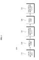
- FIG. 1 is a diagram illustrating an image display apparatus 100 according to an example embodiment.
- the image display apparatus 100 may include, for example, a light source unit 110, an optical unit 120, a variable diffuser unit 130, a pixel unit 140, and a vertical diffusion unit 150.
- the image display apparatus 100 may further include a field stop filter (not shown).
- the image display apparatus 100 may further include a high-speed switching control unit (not shown).
- the light source unit 110 may project basic beams used for displaying pixel information, and may include at least one light source. Also, the light source may be inversely located on any location of the image display apparatus, for example a front surface side and side surface side of an image panel.
- the optical unit 120 may generate a directional light using a light projected from the light source.
- the optical unit 120 may include a parallel beam-generation unit (not shown) to change the light projected from the light source unit into parallel beams, and a directional light-generation unit (not shown) to generate a directional light for generating 3D images.
- the parallel beam-generation unit may change the light projected from the light source into parallel beams.
- a light radially projected from the light source for the purpose of generating parallel beams may be first changed into parallel beams via a Fresnel lens, and may be further changed into more parallel beams through a light collimation unit.
- the directional light-generation unit may generate a directional light for generating 3D images.
- the parallel beams generated in the parallel beam-generation unit may be changed into the directional light having directivity using a lenticular lens.
- the variable diffuser unit 130 may control diffusion of the directional light.
- the control of the diffusion may be performed such that power is applied to a variable diffuser, and a state of the variable diffuser is controlled to be in a transparent state or a diffusing state.
- the directional light When in the transparent state, the directional light may be directly transmitted to display 3D images, and when in the diffusing state, the directional light may be totally diffused to display 2D images.
- the pixel unit 140 may generate 2D or 3D images that correspond to the control of the variable diffuser unit 130. Specifically, 3D images may be generated when the state of the variable diffuser is in the transparent state according to the control of the variable diffuser unit 130, and 2D images may be generated when in the diffusing state.
- the vertical diffusion unit 150 may diffuse the 3D images in a vertical direction. Specifically, a diffusion light may be generated in the vertical direction and a directional light may be generated in a horizontal direction to thereby output 3D images, when the state of the variable diffuser is in the transparent state.
- the field stop filter (not shown) may be located at a focus of the lens, and may block a light that does not pass through the focus of the lens. By using the field stop filter 150, a more precise directional light may be generated.
- the high-speed switching control unit (not shown) may high-speed switch the variable diffuser to control the 2D images and the 3D images to be simultaneously output.
- a screen capable of changing diffusion characteristics without changing lenses may be arranged to selectively display 2D images and 3D images, thereby implementing a lens having greater precision and displaying high quality 2D and 3D images.
- the variable diffuser may be easily manufactured, thereby enhancing mass productivity of a system and reducing costs.
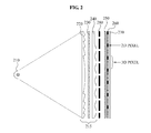
- FIG. 2 is a diagram illustrating a detailed configuration of an image display apparatus according to an example embodiment.
- the image display apparatus may include, for example, a light source unit 210, optical units 215, a variable diffuser unit 250, a pixel unit 260, a vertical diffusion unit 270, and a field stop filter 280.
- the light source unit 210 may include at least one light source, and light sources such as a metal halide lamp, a Light Emitting Diode (LED), a Cold Cathode Fluorescent Lamp (CCFL), and the like may be used as a white light source for a general projection display. Also, a location of the light source may be arranged on a front surface of a panel as shown in FIG. 2 , and also may be arranged on other locations such as a side surface of the panel.
- light sources such as a metal halide lamp, a Light Emitting Diode (LED), a Cold Cathode Fluorescent Lamp (CCFL), and the like may be used as a white light source for a general projection display.
- a location of the light source may be arranged on a front surface of a panel as shown in FIG. 2 , and also may be arranged on other locations such as a side surface of the panel.
- the optical units 215 may include parallel beam-generation units 220 and 230, and a directional light-generation unit 240.
- the parallel beam-generation units 220 and 230 may include a lens to change a light radially projected from the light source into first parallel beams, and a light collimation unit to change the first parallel beams into second parallel beams.
- the lens and the light collimation unit may be comprised of a Fresnel lens and a light collimator.
- the Fresnel lens may be used for guiding light beams to become parallel.
- Optical glasses such as a crown glass, a flint glass, and the like, and optical plastics such as acrylic, polymethyl methacrylate (PMMA), and the like, may be used as the Fresnel lens.
- the light collimator may be an optical film for changing the first parallel beams into the second parallel beams, and permitting only parallel beams to pass through the optical film. In this instance, the second parallel beams are more parallel than the first parallel beams.
- the directional light-generation unit 240 may generate a directional light for generating 3D images by refracting the second parallel beams.
- the directional light-generation unit 240 may use a lenticular lens.
- the lenticular lens may be fabricated using an optical glass such as the Fresnel lens and an optical plastic, and may be selected according to characteristics of a refractive index.
- the variable diffuser unit 250 may control diffusion of the directional light based on 2D images or 3D images to generate the 2D images or the 3D images.
- a power may be applied to a variable diffuser to change the variable diffuser to a transparent state.
- the power may not be applied to the variable diffuser to change the variable diffuser to a diffusing state.
- the variable diffuser may be changed to be in the transparent state or the diffusing state according to a presence/absence of power and a polymer-dispersed liquid crystal (PDLC) may be used as the variable diffuser.
- PDLC polymer-dispersed liquid crystal
- the pixel unit 260 may generate 3D images or 2D images to correspond to the control of the variable diffuser unit 250. Specifically, the directional light may be directly transmitted or diffused according to the state of the variable diffuser, thereby generating the 2D images and the 3D images while passing through the pixel unit 260.
- a vertical diffusion unit 270 may diffuse the transmitted directional light in a vertical direction to thereby generate diffusion light in the vertical direction, and directional light in a horizontal direction.
- a vertical diffusion screen may be a film having diffusion characteristics only in a vertical direction, and may be comprised of holographic optical elements (HOEs).
- the field stop filter 280 may be located at a focus of the lens of the directional light-generation unit 240, and block a light that does not pass through the focus of the lens. As a result, more precise directional light may be obtained.
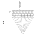
- FIG. 3 is a diagram illustrating three dimensional (3D) image display operations of the image display apparatus of FIG. 2
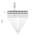
- FIG. 4 is a diagram illustrating 2D image display operations of the image display apparatus of FIG. 2 .
- a light generated in a light source for the purpose of generating 3D images may be changed into parallel beams via the Fresnel lens and a light collimation unit.
- the parallel beams may then be changed into a directional light via the lenticular lens and the field stop filter.
- a light may be transmitted via a variable diffuser 310 that is in the transparent state, and stereo-images or multi-view images may be generated by the pixel unit.
- the diffusion light and directional light may be respectively generated in a vertical direction and horizontal direction by the vertical diffusion screen. Accordingly, in this case, a user may view 3D images.
- a variable diffuser 410 may be changed to be in a diffusing state so as to output 2D images, and a light having no directivity may be generated by totally diffusing an incident light.
- the pixel unit may display 2D images, and accordingly the user may view 2D images.
- the vertical diffusion screen may diffuse the light only in the vertical direction, and may not perform any function because the light has been already totally diffused.
- FIG. 5 is a diagram illustrating a detailed configuration of an image display apparatus according to another example embodiment.
- the image display apparatus may include, for example, a light source unit 510, optical units 520, 530, and 540, a pixel unit 560, a variable diffuser 550, a vertical diffusion unit 570, and a field stop filter 580.
- the pixel unit 560 may generate images using a directional light generated in the optical units 520, 530, and 540.
- the variable diffuser 550 may control diffusion of the images generated in the pixel unit 560.
- a principle for shifting and outputting 2D images and 3D images may be similar to that illustrated in FIG. 2 .
- a location where images are generated may be moved forward to the location where the variable diffuser is positioned, in contrast with the location illustrated in FIG. 2 .
- locations of the pixel unit 560 and the variable diffuser 560 may be interchanged with each other, and may have similar results to those in FIG. 2 .
- FIG. 6 is a diagram illustrating a detailed configuration of an image display apparatus according to still another example embodiment. Specifically, an example of the image display apparatus capable of shifting 2D images and 3D images when having a plurality of light sources 610 is illustrated in FIG. 6 .
- the image display apparatus may include, for example, a plurality of light sources 610, a collimation lens 620 for generating parallel beams, a light collimation unit 630, a lenticular lens 640, a field stop filter 680, a variable diffuser 650, a pixel unit 660, and a vertical diffusion unit 670.
- the collimation lens 620 may be used instead of the Fresnel lens.
- the collimation lens 620 may function to generate parallel beams and may be implemented by the lenticular lens 640.
- locations of the variable diffuser 650 and the pixel unit 660 may be interchanged with each other.
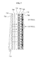
- FIG. 7 is a diagram illustrating a detailed configuration of an image display apparatus according to yet another example embodiment. Specifically, an example of the image display apparatus having the light source disposed on a side of the image display apparatus is illustrated in FIG. 7 .
- the image display apparatus may include, for example, a light source 710, a light guidance unit 720 to guide a light projected from the light source, a light deflection filter 730, a light collimation unit 740, a lenticular lens 750, a field stop filter 790, a variable diffusion unit 760, a pixel unit 770, and a vertical diffusion unit 780.
- parallel beams may be generated using the light guidance unit 720 and the light deflection filter 730 for changing the light emitted from a light guidance plate into parallel beams.
- wedge-type optical glasses or optical plastics may be used as the light guidance plate, and an optical film for changing a light obliquely emitted from the light guidance plate into parallel beams may be used as the light deflection filter 730.
- locations of the variable diffuser 650 and pixel unit 660 may be interchanged with each other.
- FIG. 8 is a flowchart illustrating an image display method according to an example embodiment.
- the method may generate a directional light using a light projected from a light source.
- the method may generate parallel beams using the light projected from the light source, and may refract the parallel beams to generate a directional light.
- the method may change a light radially emitted from the light source into first parallel beams using a Fresnel lens, change the first parallel beams into second parallel beams using a light collimation unit, and refract the second parallel beams to generate the directional light using a lenticular lens.
- the method may further include an operation for blocking a light not passing through a focus of the lenticular lens from among lights refracted by the lenticular lens.
- a field stop filter may be disposed on the focus of the lenticular lens, so that the light not passing through the focus of the lenticular lens is blocked from passing through the field stop filter, thereby generating a more precise directional light.
- the method may transmit or diffuse the directional light to generate 2D images or 3D images.
- the method may transmit or diffuse the directional light generated through the lenticular lens according to a change in a state of a variable diffuser to thereby generate the 2D images or the 3D images.
- the method may diffuse the 3D images in a vertical direction. Specifically, the method may diffuse a light passing through the variable diffuser in the vertical direction. In this instance, when the variable diffuser is in a transparent state, the directional light may be directly transmitted, and may output a diffusion light in a vertical direction and the directional light in a horizontal direction. Also, when the variable diffuser is in a diffusing state, the directional light has already been totally diffused, so that the vertical diffusion unit may not perform any specific function.
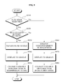
- FIG. 9 is a flowchart illustrating an image display method according to another example embodiment.
- the method may estimate whether a 3D mode is selected so as to output 2D images or 3D images. Specifically, when the 3D mode is selected through a user mode, 3D images may be outputted.
- the method may determine whether contents support the 3D mode when the 3D mode is selected. When the contents do not support the 3D mode, the 2D images may be output.
- the method may generate 3D images having directivity when the contents are determined to support the 3D mode.
- the 3D images may be stereo-images or multi-view images.
- the method may further include an operation for generating parallel beams using a light projected from a light source, and an operation for refracting the parallel beams to generate a directional light.
- the method may display the generated 3D images on a panel.
- the method may apply power to the variable diffuser to change the variable diffuser to a transparent state, thereby enabling the user to view 3D images.
- the method may remove non-uniformity in brightness of the 2D images when the 2D mode is selected in operation S910 or when the contents do not support the 3D mode in operation S920.
- the method may display, on the panel, the 2D images from which the non-uniformity in brightness of the 2D images is removed.
- the method may change the variable diffuser to be in a diffusing state to enable the 2D images to be viewed.
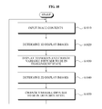
- FIG. 10 is a flowchart illustrating an image display method for simultaneously displaying 2D images and 3D images according to an exemplary embodiment.
- the method according to the present example embodiment may receive image contents.
- the method may determine a region for displaying 3D images.
- the method may display the 3D images, and change the variable diffuser to be in a transparent state.
- the method may determine a region for displaying 2D images.
- the method may display the 2D images, and change the variable diffuser to be in a diffusing state. In this instance, the method may high-speed switch the variable diffuser, thereby simultaneously displaying the 2D images and the 3D images.
- a precise lens may be used without changing a shape of a lens, and 2D images or 3D images may be displayed using a variable diffuser, thereby reducing deterioration in image quality of the 2D images and the 3D images, and outputting high quality images.
- variable diffuser that is easily manufactured may be used, thereby increasing mass-productivity of a system, and reducing costs.
Landscapes
- Physics & Mathematics (AREA)
- Engineering & Computer Science (AREA)
- Multimedia (AREA)
- Signal Processing (AREA)
- Optics & Photonics (AREA)
- General Physics & Mathematics (AREA)
- Nonlinear Science (AREA)
- Chemical & Material Sciences (AREA)
- Crystallography & Structural Chemistry (AREA)
- Mathematical Physics (AREA)
- Devices For Indicating Variable Information By Combining Individual Elements (AREA)
- Stereoscopic And Panoramic Photography (AREA)
- Testing, Inspecting, Measuring Of Stereoscopic Televisions And Televisions (AREA)
- Overhead Projectors And Projection Screens (AREA)
Applications Claiming Priority (1)
| Application Number | Priority Date | Filing Date | Title |
|---|---|---|---|
| KR1020080099020A KR101658793B1 (ko) | 2008-10-09 | 2008-10-09 | 2d와 3d의 영상전환이 가능한 영상표시장치 및 그 방법 |
Publications (2)
| Publication Number | Publication Date |
|---|---|
| EP2175662A2 true EP2175662A2 (de) | 2010-04-14 |
| EP2175662A3 EP2175662A3 (de) | 2012-07-04 |
Family
ID=41439030
Family Applications (1)
| Application Number | Title | Priority Date | Filing Date |
|---|---|---|---|
| EP09159919A Withdrawn EP2175662A3 (de) | 2008-10-09 | 2009-05-11 | Vorrichtung und Verfahren für eine zwischen 2D- und 3D-Bildern umschaltbare Anzeige |
Country Status (4)
| Country | Link |
|---|---|
| US (1) | US8144390B2 (de) |
| EP (1) | EP2175662A3 (de) |
| JP (1) | JP5658437B2 (de) |
| KR (1) | KR101658793B1 (de) |
Cited By (2)
| Publication number | Priority date | Publication date | Assignee | Title |
|---|---|---|---|---|
| CN102081911A (zh) * | 2009-11-30 | 2011-06-01 | 乐金显示有限公司 | 立体图像显示设备及其驱动方法 |
| CN103562777A (zh) * | 2011-05-30 | 2014-02-05 | 皇家飞利浦有限公司 | 自动立体显示设备 |
Families Citing this family (31)
| Publication number | Priority date | Publication date | Assignee | Title |
|---|---|---|---|---|
| US20120319999A1 (en) * | 2010-03-08 | 2012-12-20 | Dai Nippon Printing Co., Ltd. | Screens for use as displays of small-sized display devices with touch panel functions, and small-sized display devices with touch panel functions comprising said screens |
| JP5045826B2 (ja) | 2010-03-31 | 2012-10-10 | ソニー株式会社 | 光源デバイスおよび立体表示装置 |
| US9053562B1 (en) | 2010-06-24 | 2015-06-09 | Gregory S. Rabin | Two dimensional to three dimensional moving image converter |
| KR101645465B1 (ko) * | 2010-07-23 | 2016-08-04 | 삼성전자주식회사 | 휴대용 단말기에서 입체 영상 데이터를 생성하기 위한 장치 및 방법 |
| JP4930631B2 (ja) | 2010-09-27 | 2012-05-16 | ソニー株式会社 | 立体表示装置 |
| TW201224515A (en) * | 2010-12-13 | 2012-06-16 | Ind Tech Res Inst | Display with dimension switchable function |
| US20120169711A1 (en) * | 2011-01-05 | 2012-07-05 | Nokia Corporation | Method and apparatus for removing image artifacts in display related mode changes |
| JP5674023B2 (ja) | 2011-01-27 | 2015-02-18 | ソニー株式会社 | 光源デバイスおよび表示装置 |
| JP4973794B1 (ja) | 2011-04-06 | 2012-07-11 | ソニー株式会社 | 表示装置 |
| JP2012237961A (ja) | 2011-04-28 | 2012-12-06 | Sony Corp | 表示装置および電子機器 |
| KR101933455B1 (ko) * | 2011-11-23 | 2019-01-02 | 삼성전자주식회사 | 입체영상 디스플레이 장치 |
| KR20140015804A (ko) * | 2012-07-25 | 2014-02-07 | 엘지전자 주식회사 | 오토스테레오스코픽 디스플레이 및 입체영상 디스플레이 방법 |
| KR20140050129A (ko) * | 2012-10-17 | 2014-04-29 | 삼성전자주식회사 | 다시점 및 초다시점 영상을 디스플레이하는 장치 및 방법 |
| KR102059783B1 (ko) * | 2012-12-29 | 2020-02-20 | 엘지디스플레이 주식회사 | 홀로그램 광학소자를 포함하는 백 라이트 유닛 및 이를 이용한 입체 영상 표시 장치 |
| US9992021B1 (en) | 2013-03-14 | 2018-06-05 | GoTenna, Inc. | System and method for private and point-to-point communication between computing devices |
| CN104049372B (zh) * | 2014-06-24 | 2016-02-17 | 深圳超多维光电子有限公司 | 2d/3d可切换显示装置 |
| JP6327062B2 (ja) * | 2014-08-25 | 2018-05-23 | オムロン株式会社 | 表示装置 |
| TWI572906B (zh) * | 2015-02-25 | 2017-03-01 | 台達電子工業股份有限公司 | 立體光場建立裝置 |
| TWI607244B (zh) * | 2015-11-13 | 2017-12-01 | 台達電子工業股份有限公司 | 顯示裝置 |
| EP3598203B1 (de) | 2017-04-28 | 2021-09-15 | Cloudminds (Shenzhen) Robotics Systems Co., Ltd. | Direktionaler optischer wellenleiter, direktionales rückbeleuchtungsmodul und anzeigevorrichtung |
| US20200228764A1 (en) * | 2017-10-02 | 2020-07-16 | Liqxtal Technology Inc. | Tunable light projector |
| US11126060B2 (en) * | 2017-10-02 | 2021-09-21 | Liqxtal Technology Inc. | Tunable light projector |
| JP2019139227A (ja) * | 2018-02-14 | 2019-08-22 | 国立大学法人東北大学 | 立体映像液晶表示装置 |
| TWI778262B (zh) * | 2019-02-13 | 2022-09-21 | 源奇科技股份有限公司 | 可調式光投射器 |
| TWI747224B (zh) * | 2019-04-01 | 2021-11-21 | 源奇科技股份有限公司 | 可調式光投射器 |
| CN110361870A (zh) * | 2019-07-29 | 2019-10-22 | 深圳阜时科技有限公司 | 一种光学组件、发射单元、传感模组及电子设备 |
| CN110426899A (zh) * | 2019-07-29 | 2019-11-08 | 深圳阜时科技有限公司 | 一种发射单元、传感模组及电子设备 |
| US11733598B2 (en) * | 2019-12-04 | 2023-08-22 | Liqxtal Technology Inc. | Tunable light projector |
| CN119213758A (zh) * | 2022-09-26 | 2024-12-27 | 三星电子株式会社 | 立体显示装置及立体显示方法 |
| WO2024223099A1 (en) * | 2023-04-28 | 2024-10-31 | Realfiction Lab Aps | A multiview display |
| KR20250004485A (ko) | 2023-06-30 | 2025-01-08 | 삼성디스플레이 주식회사 | 표시 장치 및 이의 제조 방법 |
Citations (3)
| Publication number | Priority date | Publication date | Assignee | Title |
|---|---|---|---|---|
| EP0631170A2 (de) * | 1993-06-24 | 1994-12-28 | International Business Machines Corporation | System zur Rückbeleuchtung für transmissive Anzeige |
| US20030137730A1 (en) * | 2002-01-23 | 2003-07-24 | Sergey Fridman | Autostereoscopic display |
| US20050259148A1 (en) * | 2004-05-14 | 2005-11-24 | Takashi Kubara | Three-dimensional image communication terminal |
Family Cites Families (29)
| Publication number | Priority date | Publication date | Assignee | Title |
|---|---|---|---|---|
| JPH087329B2 (ja) * | 1986-05-19 | 1996-01-29 | コニカ株式会社 | 光情報の記録再生用光学系 |
| JP3083635B2 (ja) * | 1992-04-03 | 2000-09-04 | 日本電信電話株式会社 | 3次元立体画像/2次元画像共存型表示装置 |
| GB2272555A (en) | 1992-11-11 | 1994-05-18 | Sharp Kk | Stereoscopic display using a light modulator |
| JPH07133893A (ja) | 1993-11-11 | 1995-05-23 | Sanyo Electric Co Ltd | 天然ガス充填装置 |
| JPH08149520A (ja) | 1994-11-16 | 1996-06-07 | Sanyo Electric Co Ltd | 立体映像表示装置 |
| JP2951264B2 (ja) | 1995-05-24 | 1999-09-20 | 三洋電機株式会社 | 2次元映像/3次元映像互換型映像表示装置 |
| JPH08322067A (ja) * | 1995-05-24 | 1996-12-03 | Sharp Corp | 3次元情報再生装置 |
| US5936774A (en) * | 1995-08-29 | 1999-08-10 | Street; Graham S. B. | Autostereoscopic display |
| JP2000502225A (ja) * | 1995-12-09 | 2000-02-22 | ストリート・グレイアム・スチワート・ブランダン | 自動立体表示器 |
| US5897184A (en) * | 1996-07-02 | 1999-04-27 | Dimension Technologies, Inc. | Reduced-thickness backlighter for autostereoscopic display and display using the backlighter |
| JPH10268805A (ja) | 1997-03-26 | 1998-10-09 | Shinichi Hirabayashi | 2d/3d画像表示装置 |
| JP3731039B2 (ja) * | 1997-06-23 | 2006-01-05 | 日本ビクター株式会社 | カラー立体画像表示装置 |
| US6157424A (en) | 1998-03-30 | 2000-12-05 | Dimension Technologies, Inc. | 2D/3D imaging display |
| JP2001091896A (ja) | 1999-09-24 | 2001-04-06 | Sanyo Electric Co Ltd | 2次元映像/3次元映像互換型映像表示装置 |
| JP2001330713A (ja) | 2000-05-22 | 2001-11-30 | Namco Ltd | フィルター、および、電子機器 |
| JP2002251910A (ja) * | 2001-02-22 | 2002-09-06 | Alps Electric Co Ltd | 照明装置及びこれを用いた液晶表示装置 |
| GB0317714D0 (en) | 2003-07-29 | 2003-09-03 | Koninkl Philips Electronics Nv | Autostereoscopic display apparatus |
| GB2405546A (en) * | 2003-08-30 | 2005-03-02 | Sharp Kk | Dual view directional display providing images having different angular extent. |
| GB0326005D0 (en) | 2003-11-07 | 2003-12-10 | Koninkl Philips Electronics Nv | Waveguide for autostereoscopic display |
| GB0328005D0 (en) | 2003-12-03 | 2004-01-07 | Koninkl Philips Electronics Nv | 2D/3D Displays |
| JP4341751B2 (ja) * | 2004-02-17 | 2009-10-07 | 誠次郎 富田 | 立体映像記録・再生方法並びにこれを表示する立体映像表示装置 |
| US7283308B2 (en) * | 2004-03-05 | 2007-10-16 | Actuality Systems, Inc. | Optical systems for generating three-dimensional images |
| JP4572743B2 (ja) * | 2004-05-28 | 2010-11-04 | サンテックオプト株式会社 | バックライト用屈折集光板 |
| US20060176557A1 (en) | 2005-02-09 | 2006-08-10 | Adrian Travis | 2D/3D compatible display system |
| KR101118744B1 (ko) | 2005-03-02 | 2012-03-14 | 재단법인서울대학교산학협력재단 | 3차원/2차원 변환 가능 영상 표시 장치 |
| WO2006093365A1 (en) * | 2005-03-02 | 2006-09-08 | Seoul National University Industry Foundation | Three-dimensional/ two-dimensional convertible display device |
| US8675125B2 (en) * | 2005-04-27 | 2014-03-18 | Parellel Consulting Limited Liability Company | Minimized-thickness angular scanner of electromagnetic radiation |
| KR101170797B1 (ko) | 2005-07-26 | 2012-08-02 | 삼성전자주식회사 | 완전 결상 방식의 입체 영상 표시 장치 |
| KR100893616B1 (ko) * | 2006-04-17 | 2009-04-20 | 삼성모바일디스플레이주식회사 | 전자 영상 기기, 2d/3d 영상 표시 장치 및 그 구동방법 |
-
2008
- 2008-10-09 KR KR1020080099020A patent/KR101658793B1/ko not_active Expired - Fee Related
-
2009
- 2009-03-20 US US12/382,684 patent/US8144390B2/en not_active Expired - Fee Related
- 2009-04-22 JP JP2009103815A patent/JP5658437B2/ja not_active Expired - Fee Related
- 2009-05-11 EP EP09159919A patent/EP2175662A3/de not_active Withdrawn
Patent Citations (3)
| Publication number | Priority date | Publication date | Assignee | Title |
|---|---|---|---|---|
| EP0631170A2 (de) * | 1993-06-24 | 1994-12-28 | International Business Machines Corporation | System zur Rückbeleuchtung für transmissive Anzeige |
| US20030137730A1 (en) * | 2002-01-23 | 2003-07-24 | Sergey Fridman | Autostereoscopic display |
| US20050259148A1 (en) * | 2004-05-14 | 2005-11-24 | Takashi Kubara | Three-dimensional image communication terminal |
Cited By (3)
| Publication number | Priority date | Publication date | Assignee | Title |
|---|---|---|---|---|
| CN102081911A (zh) * | 2009-11-30 | 2011-06-01 | 乐金显示有限公司 | 立体图像显示设备及其驱动方法 |
| CN102081911B (zh) * | 2009-11-30 | 2013-04-10 | 乐金显示有限公司 | 立体图像显示设备及其驱动方法 |
| CN103562777A (zh) * | 2011-05-30 | 2014-02-05 | 皇家飞利浦有限公司 | 自动立体显示设备 |
Also Published As
| Publication number | Publication date |
|---|---|
| KR20100039999A (ko) | 2010-04-19 |
| US20100091354A1 (en) | 2010-04-15 |
| JP2010092006A (ja) | 2010-04-22 |
| JP5658437B2 (ja) | 2015-01-28 |
| EP2175662A3 (de) | 2012-07-04 |
| US8144390B2 (en) | 2012-03-27 |
| KR101658793B1 (ko) | 2016-09-23 |
Similar Documents
| Publication | Publication Date | Title |
|---|---|---|
| EP2175662A2 (de) | Vorrichtung und Verfahren für eine zwischen 2D- und 3D-Bildern umschaltbare Anzeige | |
| US9194997B2 (en) | Backlight unit and 2D and 3D image display system | |
| US9462261B2 (en) | 2D/3D switchable autostereoscopic display apparatus and method | |
| JP5674023B2 (ja) | 光源デバイスおよび表示装置 | |
| CN100430762C (zh) | 用于3d显示设备的背光 | |
| CN103984110B (zh) | 多视域显示器 | |
| US20070296920A1 (en) | Rear Projection Screen and Associated Display System | |
| US20110216407A1 (en) | Lighting device for an autostereoscopic display | |
| US20080186575A1 (en) | 2d-3d image switching display system | |
| JP2013076725A (ja) | 光源デバイスおよび表示装置、ならびに電子機器 | |
| KR20120069432A (ko) | 입체영상표시장치 및 그 구동 방법 | |
| JP2000092520A (ja) | 立体映像表示装置 | |
| JP2010237416A (ja) | 立体表示装置 | |
| TWI537604B (zh) | 顯示裝置、可變視差屏障模組及顯示方法 | |
| US10750159B2 (en) | 3D image display apparatus and image display method thereof | |
| JP2017506762A (ja) | デュアルビューイングフィルム及びこれを使用したデュアルビューディスプレイ装置 | |
| JP2013083904A (ja) | 光源デバイスおよび表示装置、ならびに電子機器 | |
| CN106199987A (zh) | 一种基于连续背光指向的裸眼3d显示系统 | |
| US6727866B2 (en) | Parallax barrier type autostereoscopic display device | |
| CN102841446B (zh) | 立体图像显示装置及其驱动方法 | |
| JP2007179059A (ja) | 携帯機器 | |
| CN105044918B (zh) | 一种2d/3d可切换的集成成像立体显示装置 | |
| JP2009093989A (ja) | 面光源装置及び液晶表示装置 | |
| JP2011145349A (ja) | 表示装置 | |
| KR20170044906A (ko) | 백 라이트 장치 및 이를 포함하는 3차원 영상 표시 장치 |
Legal Events
| Date | Code | Title | Description |
|---|---|---|---|
| PUAI | Public reference made under article 153(3) epc to a published international application that has entered the european phase |
Free format text: ORIGINAL CODE: 0009012 |
|
| AK | Designated contracting states |
Kind code of ref document: A2 Designated state(s): AT BE BG CH CY CZ DE DK EE ES FI FR GB GR HR HU IE IS IT LI LT LU LV MC MK MT NL NO PL PT RO SE SI SK TR |
|
| PUAL | Search report despatched |
Free format text: ORIGINAL CODE: 0009013 |
|
| AK | Designated contracting states |
Kind code of ref document: A3 Designated state(s): AT BE BG CH CY CZ DE DK EE ES FI FR GB GR HR HU IE IS IT LI LT LU LV MC MK MT NL NO PL PT RO SE SI SK TR |
|
| RIC1 | Information provided on ipc code assigned before grant |
Ipc: H04N 13/00 20060101AFI20120525BHEP Ipc: G02B 27/22 20060101ALI20120525BHEP |
|
| RAP1 | Party data changed (applicant data changed or rights of an application transferred) |
Owner name: SAMSUNG ELECTRONICS CO., LTD. |
|
| 17P | Request for examination filed |
Effective date: 20130104 |
|
| 17Q | First examination report despatched |
Effective date: 20171121 |
|
| STAA | Information on the status of an ep patent application or granted ep patent |
Free format text: STATUS: THE APPLICATION IS DEEMED TO BE WITHDRAWN |
|
| 18D | Application deemed to be withdrawn |
Effective date: 20180404 |