EP2175668A1 - Resonatorsystem für einen Sprecher einer elektronischen Vorrichtung - Google Patents
Resonatorsystem für einen Sprecher einer elektronischen Vorrichtung Download PDFInfo
- Publication number
- EP2175668A1 EP2175668A1 EP09172485A EP09172485A EP2175668A1 EP 2175668 A1 EP2175668 A1 EP 2175668A1 EP 09172485 A EP09172485 A EP 09172485A EP 09172485 A EP09172485 A EP 09172485A EP 2175668 A1 EP2175668 A1 EP 2175668A1
- Authority
- EP
- European Patent Office
- Prior art keywords
- enclosure
- speaker
- transducer
- port
- resonator
- Prior art date
- Legal status (The legal status is an assumption and is not a legal conclusion. Google has not performed a legal analysis and makes no representation as to the accuracy of the status listed.)
- Granted
Links
Images


Classifications
-
- H—ELECTRICITY
- H04—ELECTRIC COMMUNICATION TECHNIQUE
- H04R—LOUDSPEAKERS, MICROPHONES, GRAMOPHONE PICK-UPS OR LIKE ACOUSTIC ELECTROMECHANICAL TRANSDUCERS; ELECTRIC HEARING AIDS; PUBLIC ADDRESS SYSTEMS
- H04R1/00—Details of transducers, loudspeakers or microphones
- H04R1/20—Arrangements for obtaining desired frequency or directional characteristics
- H04R1/22—Arrangements for obtaining desired frequency or directional characteristics for obtaining desired frequency characteristic only
- H04R1/28—Transducer mountings or enclosures modified by provision of mechanical or acoustic impedances, e.g. resonator, damping means
- H04R1/2807—Enclosures comprising vibrating or resonating arrangements
- H04R1/2815—Enclosures comprising vibrating or resonating arrangements of the bass reflex type
- H04R1/2819—Enclosures comprising vibrating or resonating arrangements of the bass reflex type for loudspeaker transducers
-
- H—ELECTRICITY
- H04—ELECTRIC COMMUNICATION TECHNIQUE
- H04R—LOUDSPEAKERS, MICROPHONES, GRAMOPHONE PICK-UPS OR LIKE ACOUSTIC ELECTROMECHANICAL TRANSDUCERS; ELECTRIC HEARING AIDS; PUBLIC ADDRESS SYSTEMS
- H04R2499/00—Aspects covered by H04R or H04S not otherwise provided for in their subgroups
- H04R2499/10—General applications
- H04R2499/11—Transducers incorporated or for use in hand-held devices, e.g. mobile phones, PDA's, camera's
Definitions
- the disclosure herein describes a resonator for a transducer of an electronic device.
- the disclosure includes one or more enclosures for a speaker that act as resonator(s) to modify acoustic characteristics of the speaker.
- a speaker is an acoustic transducer which is commonly provided with a device as an audio output device.
- a feature of an embodiment provides acoustic tuning for transducers in electronic devices.
- a brief description of some notable general aspects of embodiments are first provided. Then, some general functional elements of a device incorporating an embodiment are provided, followed by more details on notable features of an embodiment.
- a resonator for a transducer of an electronic device comprises: a first enclosure having a first opening to receive a back end of the transducer and a second opening; and a port connected to the first enclosure through the second opening of the enclosure, the port having a first end, a second end, an interior channel spanning from the first end to the second end.
- a first volume in the first enclosure between the transducer and the first enclosure namely the interior sides of the first enclosure
- the transducer and the resonator may be mounted on a printed circuit board of the electronic device.
- the resonator may further comprise a second enclosure to cover a front portion of the transducer, the second enclosure including at least one aperture to allow air outside of the device to be in communication with the front of the transducer.
- the second end of the port may connect with an opening in a housing of the device to be in communication with air surrounding the device.
- the transducer may be a speaker.
- the port may have a length of between approximately 1 mm and 10 mm and an opening in the second side of the port for the interior channel may have an area of between approximately 0.5 and 8 mm 2 .
- the first enclosure may have dimensions to provide the first volume to be approximately 0.2 cm 3 or less.
- the first enclosure may be rectangular in shape.
- the first enclosure may have exterior dimensions of approximately 13 mm by 15 mm by 4 mm.
- the resonator may equalize a frequency response of the transducer to be in a frequency range of between about 2 kHz and 3.5 kHz.
- the first enclosure may be plastic.
- the second enclosure may rectangular in shape.
- the resonator may further comprise acoustic mesh covering the second end of the port.
- At least one of the first or second enclosures may be formed in part of a housing of the electronic device.
- an acoustic system for an electronic device comprises: a speaker; a first enclosure having a first opening to receive a back end of the transducer and a second opening; a port connected to the first enclosure through the second opening of the enclosure, the port having a first end, a second end, an interior channel and a third opening in the second end; and a second enclosure to cover a front portion of the transducer.
- the second enclosure includes at least one aperture to air outside of the device to be in communication with the front of the transducer.
- the second end of the port may be connectable with an opening in a housing of the device to be in communication with air surrounding the device.
- the port may have a length of between approximately 1 mm and 10 mm and an opening in the second side of the port for the interior channel may have an area of between approximately 0.5 and 8 mm 2 .
- the first enclosure may be rectangular in shape.
- the second enclosure may be rectangular in shape.
- the first and second enclosures equalizes a frequency response of the speaker to be in a frequency range of between about 2 kHz and 3.5 kHz.
- an acoustic system for an electronic device comprises: a housing for the device; a printed circuit board; a speaker; a first enclosure having a first opening to receive a back end of the speaker and a second opening; a port connected to the first enclosure through the second opening of the enclosure, the port having a first end, a second end, an interior channel and a third opening in the second end; and a second enclosure to cover a front portion of the speaker, the second enclosure including at least one aperture to air outside of the device to be in communication with the front of the speaker.
- a first volume in the first enclosure between the transducer and the first enclosure is formed which is in communication with air surrounding the second end of the port through the interior channel of the port.
- the third opening of the port is connected with an opening in the housing to be in communication with air surrounding the device.
- the speaker with the first and second enclosures may be mounted on the printed circuit board.
- the first enclosure may be rectangular in shape.
- an electronic device for receiving electronic communications in accordance with an embodiment of the disclosure is indicated generally at 10.
- electronic device 10 is based on a computing platform having exemplary functionality of an enhanced personal digital assistant such as cellphone, e-mail, photographic and media playing features. It is, however, to be understood that electronic device 10 can be based on construction design and functionality of other electronic devices, such as smart telephones, desktop computers pagers or laptops having telephony equipment.
- electronic device 10 includes a housing 12 comprising front housing 12A and rear housing 12B (not shown).
- a display 14 There may be one or more components in device 10, including, for example any of: a display 14, front speaker 16A (shown through opening 17 in front housing 12A), a light emitting diode (LED) indicator 18, a trackball 20, a trackwheel (not shown), an ESC ("escape") key 22, keys 24, touchpad (not shown), a telephone headset comprised of an ear bud 25 and a microphone 28.
- Display 14 may be a liquid crystal display (LCD) and may incorporate a touchscreen.
- Trackball 20 and ESC key 22 can be inwardly depressed as a means to provide additional input signals to device 10.
- Other components may also be provided in device 10. Apertures may be provided in housing 12 to allow access to components located inside device 10.
- aperture 17 is provided to allow sound generated by speaker 16A to emanate out of device 10.
- Another aperture (not shown) is provided that provides an air connection for a back enclosure of speaker 16A (described below). Any embodiment may implement one or more of any of the above noted components therein. It may not be necessary to have any of the above noted components in an embodiment.
- Housing 12 may be made from a plastic material, such as polycarbonate. Its components may be formed via an injection molding process. It may have coatings, such as metallicized paints or coatings provided to interior or exterior surfaces or regions. Housing 12 can be made from any suitable material (such as metal) as will occur to those of skill in the art and may be suitably formed to house and hold all components of device 10.
- Device 10 is operable to conduct wireless telephone calls, using any known wireless phone system such as a Global System for Mobile Communications (“GSM”) system, Code Division Multiple Access (“CDMA”) system, Cellular Digital Packet Data (“CDPD”) system and Time Division Multiple Access (“TDMA”) system.
- GSM Global System for Mobile Communications
- CDMA Code Division Multiple Access
- CDPD Cellular Digital Packet Data
- TDMA Time Division Multiple Access
- Other wireless phone systems can include Bluetooth and the many forms of 802.11 wireless broadband, like 802.11a, 802.11b, 802.11 g, etc. that support voice.
- Other embodiments include Voice over IP (VoIP) type streaming data communications that can simulate circuit switched phone calls.
- Output audio signals are produced on any of speakers 16A and / or 16B.
- Ear bud 25 can be used to listen to phone calls and other sound messages and microphone 28 can be used to speak into and input sound messages to device 10.
- GUI graphical user interface
- Keys 24 provide one or more distinct, fixed input keys for device 10. Typically, they may include at least part of keys in an alphanumeric character set.
- a touchpad may be provided and configured to provide an additional set of "keys" (or input areas) to augment keys 24. Keys may also be incorporated into part of a touchscreen on device 10.
- the functional elements are generally electronic or electro-mechanical devices mounted within a housing. Many devices are also mounted on an internal substrate, such as a printed circuit board (PCB).
- a substrate is any generally planar rigid platform.
- PCB 76 is a substrate for mounting and supporting the internal components on both of its top and bottom sides and provides some electrical circuitry for the devices, as defined by etchings within the layers of plastic and copper. As such, components can be more densely packed thereon, thereby reducing the size of PCB 76.
- PCB 76 is securely mountable within housing 12, typically via screws.
- PCB 76 is a generally planar sandwich of layers of plastic (or FR4) and copper.
- PCB 76 allows components to be placed on both of its sides ("top” and “bottom”). Some components may require isolation or sufficient physical separation from other components. For example, radio frequency (RF) signals from antenna may interfere with the operation of other devices. Shielding may be provided. Further details on these components and layouts are provided below.
- RF radio frequency
- Microprocessor 30 is provided to control and receive almost all data, transmissions, inputs and outputs related to device 10.
- Microprocessor 30 is shown schematically as coupled to keys 24, touchpad, display 14 and other internal devices.
- Microprocessor 30 controls the operation of display 14, as well as the overall operation of device 10, in response to actuation of keys 24 and keys on touchpad.
- Exemplary microprocessors for microprocessor 30 include microprocessors in the Data 950 (trade-mark) series, the 6200 series and the PX900 series, all available at one time from Intel Corporation.
- other internal devices of device 10 include: a communication subsystem 34; a short-range communication subsystem 36; touchpad; and display 14; other input/output devices including a set of auxiliary I/O devices through port 38, a serial port 40, a front speaker 16A, a back speaker 16B, and a microphone port 32 for microphone 28; and memory devices including a flash memory 42 (which provides persistent storage of data) and random access memory (RAM) 44; persistent memory 74; clock 46 and other device subsystems (not shown).
- a communication subsystem 34 a short-range communication subsystem 36; touchpad; and display 14
- other input/output devices including a set of auxiliary I/O devices through port 38, a serial port 40, a front speaker 16A, a back speaker 16B, and a microphone port 32 for microphone 28
- memory devices including a flash memory 42 (which provides persistent storage of data) and random access memory (RAM) 44; persistent memory 74; clock 46 and other device subsystems (not shown).
- Speakers are provided to generate audible output signals for device 10, for example, received voice signals for telephone calls, music from digital signals, enunciator signals generated by applications operating on device 10.
- Front speaker 16A is provided as a main audible signal generator.
- Rear speaker 16B is an auxiliary speaker and may be used to generate louder audio signals, for example for a speaker phone operation.
- One or both of speakers 16A and 16B may be selected and tuned to operate in an acoustic frequency range suitable for telephone voice transmissions, where a focus is typically placed on response characteristics of signals between about 300 Hz and about 3,300 Hz. Other ranges can be focused on depending on particular acoustic performance goals of the speaker(s).
- Back speaker 16B may be provided on the back side of housing 12B, but may also be provide on other locations in device 10, such as on its side or even on its front in its housing 12. Components in device 10 provide and generate electrical signals for speakers 16, which when received by speakers 16 are converted to acoustic signals per typical operation of a speaker. Other types and sizes of speakers may be used including speakers having cone diaphragms.
- Enclosure system 70 may be provided for speaker 16A and / or 16B to adjust response characteristics of the speaker. Further detail on the relationships between speaker 16A and enclosure system 70 is provided below.
- Communication functions are performed through communication subsystem 34 and short-range communication subsystem 36.
- subsystem 34 and subsystem 36 provide a signal-level interface for all communication technologies processed by device 10.
- Communication subsystem 34 includes receiver 50, transmitter 52 and one or more antennas, illustrated as receive antenna 54 and transmit antenna 56.
- communication subsystem 34 also includes processing module, such as digital signal processor (DSP) 58 and local oscillators (LOs) 60.
- DSP digital signal processor
- LOs local oscillators
- the specific design and implementation of communication subsystem 34 is dependent upon the communication network in which device 10 is intended to operate including one or more of a Mobitex (trade-mark) Radio Network (“Mobitex”) and the DataTAC (trade-mark) Radio Network (“DataTAC”).
- Voice-centric technologies for cellular device 10 include Personal Communication Systems (PCS) networks like Global System for Mobile Communications (GSM) and Time Division Multiple Access (TDMA) systems.
- PCS Personal Communication Systems
- GSM Global System for Mobile Communications
- TDMA Time Division Multiple Access
- Certain networks provide multiple systems including dual-mode wireless networks include Code Division Multiple Access (CDMA) networks, General Packet Radio Service (GPRS) networks, and so-called third-generation (3G) networks, such as Enhanced Data rates for Global Evolution (EDGE) and Universal Mobile Telecommunications Systems (UMTS).
- 3G Third-generation
- EDGE Enhanced Data rates for Global Evolution
- UMTS Universal Mobile Telecommunications Systems
- Other network communication technologies that may be employed include, for example, Ultra Mobile Broadband (UMB), Evolution-Data Optimized (EV-DO), and High Speed Packet Access (HSPA), etc.
- UMB Ultra Mobile Broadband
- EV-DO Evolution-Data Optimized
- HSPA High Speed Packet Access
- DSP 58 provides control of receiver 50 and transmitter 52.
- gains applied to communication signals in receiver 50 and transmitter 52 may be adaptively controlled through automatic gain control algorithms implemented in DSP 58.
- Short-range communication subsystem 36 enables communication between device 10 and other proximate systems or devices, which need not necessarily be similar devices.
- the short-range communication subsystem may include an infrared device and associated circuits and components, or a Bluetooth (trade-mark) communication module to provide for communication with similarly-enabled systems and devices.
- Operating system software executed by microprocessor 30 is preferably stored in a computer readable medium, such as flash memory 42, but may be stored in other types of memory devices (not shown), such as read only memory (ROM) or similar storage element.
- system software, specific device applications, or parts thereof may be temporarily loaded into a volatile storage medium, such as RAM 44.
- Microprocessor 30, in addition to its operating system functions, enables execution of software applications on device 10.
- Persistent memory 74 may be a separate memory system to flash memory 42 and may be incorporated into a component in device 10, such as in microprocessor 30. Additionally or alternatively, memory 74 may removable from device 10 (e.g. such as a SD memory card), whereas flash memory 42 may be permanently connected to device 10.
- Display 14 has backlight system 64 to assist in the viewing of display 14, especially under low-light conditions.
- a backlight system is typically present in a LCD.
- a typical backlight system comprises a lighting source, such as a series of LEDs or a lamp located behind the LCD panel of the display and a controller to control activation of the lighting source.
- light sensor 66 is provided on device 10. Sensor 66 may be located anywhere on device 10, having considerations for aesthetics and operation characteristics of sensor 66.
- Powering electronics of the mobile handheld communication device is power source 62 (shown in Fig. 2 as "battery”).
- the power source 62 may be one or more batteries.
- the power source 62 may be a single battery pack, such as a rechargeable battery pack. Alternative power source(s) may be provided.
- a power switch (not shown) provides an “on/off" switch for device 10.
- Voice communication module 48A handles voice-based communication such as telephone communication
- data communication module 48B handles data-based communication such as e-mail.
- one or more communication processing functions may be shared between modules 48A and 48B.
- Calendar 48C which tracks appointments and other status matters relating to the user and device 10. Calendar 48C is activated by activation of calendar icon 26A on display 14. Address book 48D enables device 10 to store contact information for persons and organizations.
- Email application 48E provides modules to allow user of device 10 to generate email messages on device 10 and send them to their addressees.
- Calculator application 48F provides modules to allow user of device 10 to create and process arithmetic calculations and display the results through a GUI.
- Any application in device 10 may produce any output signal through components on device 10.
- visual output may be provided through text and / or graphics generated on display 14. Additional separate lights and LED may provide additional output indicators.
- Audible output signals e.g. received voice signals for telephone communications, audible enunicators (e.g. "beep" signals) may be generated as output signals provided by speaker 16A.
- a buzzer in device 10 may provide another tactile feedback signal for an application.
- Database 72 is provided to store data and records for applications 48 and other modules and processes.
- Database 72 may be provided in flash memory 42 or in another data storage element.
- Acoustic and electrical properties of a transducer may be modified by providing one or more enclosures, capturing a volume of air, around parts of the transducer.
- operational characteristics of a transducer such as the resonant frequency and / or Q factors of the transducer, may be modified from its typical ambient operational characteristics.
- a transducer may be a microphone, speaker or other device.
- enclosure(s) may be provided to tune frequency response characteristics of the speaker. For example, an enclosure may be provided to reduce back-wave noise and / or to tune a resonant frequency for the speaker to a specific value.
- One or more enclosures may be provided forming an enclosure system for the speaker.
- Each enclosure may be a suitably sized cabinet to enclosure a specified volume of air around a part of the speaker. There may be one or more ports in an enclosure.
- An enclosure may provide additional functions for other components in device 10, such as radio frequency (RF) shielding.
- RF radio frequency
- An enclosure may be formed using part of other components in device 10, such as formations provided in housing 12 and / or walls provided by PCB 76.
- An aspect of an embodiment provides a first acoustic resonator connected to one side of an acoustic transducer and infinite surrounded air.
- Another aspect provides a second acoustic resonator is connected to the ear of the user on one side and to the other side of the transducer as soundgiving device on the other side.
- An acoustic resonator is realized by a system having a cavity that is filled with air and that is directly attached to either side of the transducer and a port attached to the cavity with an opening.
- the resonance frequency of the resonator is defined by the volume of air that is inside the cavity and a length and cross-section of the port.
- the combination of both acoustic resonators may be used with different resonating frequencies of the transducer to improve the target parameter acoustic frequency response in terms of linearity and bandwidth of the acoustic system in the used environment.
- An embodiment may further comprise an enclosure to either one side of the acoustic transducer and at least one aperture to allow air and sound venting outside of said device to be in communication with said either side of the transducer.
- There may be an acoustic resistance integrated in or on first the aperture. The resistance may be realized with acoustic meshes.
- one acoustic resonator aperture may be connected to the ear of the user of the electronic device.
- the other said acoustic resonator aperture may be connected to the infinite surrounding air.
- the acoustic resonator system may equalize a frequency response of the transducer at the aperture connected to the ear of the user in a frequency range of between about 1 kHz and 3.5 kHz.
- Figs. 3 to 13 provide further detail on aspects of an embodiment.
- Position / direction terms e.g. front, back, left, right, etc.
- are used herein to identify relative positions and directions for certain elements of device 10 e.g. "There is a left side and a right side of the device”
- display 14 faces the user.
- device 10 in Figure 1 may be held by a user in his hand such that display 14 is oriented in the user's hand to be above keys 24.
- the "front" side of device 10 is the side facing the user; the “back” side of device 10 is the side contacting the palm of the user's hand; the "top” side of device 10 is the upper end of device 10 (where speaker 16A is located) that extends away from the user when device 10 is being held; and the “bottom” side of device 10 is the lower end of device 10 (when keys 24 are located) that extends away from the user when device 10 is being held.
- references to front side, back side, left side, right side, and top and bottom ends are provided using the orientation markings relative to the side view of device 10 as shown in Fig. 3 .
- top and “upper” may be used interchangeably the “front” side and the “top” end of device 10 and similarly that the terms “bottom”, “rear” and “lower” may be used interchangeably with the “back” side of device 10.
- dimension terms like “width”, “length”, “height” and “depth” can be applied to different features of an element depending on a current perspective.
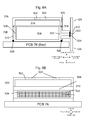
- FIG. 3 and 4 one embodiment of a speaker enclosure is shown, where the speaker enclosure is affixed, integrated, assembled to or otherwise connected with a bottom portion of a housing for a device, namely housing 12B.
- Front view of housing 12B is shown with components of device 10 populated on PCB 76 shown therein.
- speaker 16A is shown with its diaphragm oriented upwards (to project sound out of the front face of device 10, when housing 12A (not shown) is mounted to housing 12B.
- the enclosure and speaker may be located on or about the top side of the PCB. In one embodiment, being "about" the PCB refers to an enclosure that is not affixed to the PCB.
- the PCB may be mounted within a space about the PCB, being secured to the housing. In other words, it may be mounted around or proximate to the PCB, without being attached to the PCB.
- being "about" the PCB refers to an enclosure (or a part thereof) that is affixed to the PCB. Additional enclosures may be provided for other speakers, such as for a speaker mounted on the bottom side of the PCB.
- Speaker 16A is mated to enclosure system 70 comprising front enclosure 70A and back enclosure 70B. These components are shown schematically and are not necessarily presented to scale in comparison with other components shown in Figs. 3 and 4 , in particular in regards to their heights.
- Front enclosure 70A mounts to the top of speaker 16A, forming a volume of air within the interior of the front enclosure around the top of speaker 16A.
- the back enclosure 70B mounts to the backside of speaker 16A, forming a volume of air within the interior of the back enclosure around the bottom of the speaker.
- a port (not shown) is provided in back enclosure 70B and connects with aperture 17 ( Fig. 1 ) of housing 12B, to provide an air channel of the back enclosure to ambient air.
- Having a back enclosure for the bottom of speaker 16A assists in separating the air surrounding the bottom of the speaker from being in communication with the air surrounding the top of the speaker, which assists in preventing an acoustic short circuit between the top and bottom of the speaker, where the top of the speaker is in communication with the bottom of the speaker.
- the phrase that a component is "in communication" with another component for this disclosure describes an arrangement where the component is "in contact" with the other component.
- Contact may be a direct physical contact, where the components touch each other.
- Contact may be an indirect physical contact, where a linking component provides an interface to transmit a movement of one component to the other component.
- enclosure system 70 When describing acoustic properties, two components that are "in communication" with each other when audible signals generated or carried by one component are transmitted to and received by the other component, either directly or through free air or through some type of connecting channel, volume or conduit.
- Each part of enclosure system 70 may be formed from plastic, metal and / or other materials. Paint or a coating may be provided to the interior surfaces of system 70.
- front enclosure 70A provides an enclosure for a volume of air over the top of the diaphragm of speaker 16A.
- An exemplary speaker which may be used in an embodiment is a speaker the size of approximately 11 mm x 15 mm x 3.5 mm.
- the shape of the interior volume of front enclosure 70A is rectangular, as the diaphragm of speaker 16A is rectangular and has dimensions to mate with the speaker.
- Other shapes for a front enclosure may be provided to mate with the shape of the speaker.
- the exterior dimensions for the front enclosure are approximately 11 mm long by 15 mm wide by 1 mm high.
- the exterior shape of front enclosure 70A has a four vertical walls 500 and a top section 502, all connected and joined to form a box shape, with an open bottom.
- the volume of the front enclosure provides a volume of approximately 0.15 cm 3 above the front of speaker 16A.
- Different volume sizes, structures and shapes may be provided depending on the response characteristics wanted and the physical dimensions of the speaker.
- Exemplary additional volumes may be hemispherical, columnar, ovoid or any combination of such volumes.
- parts of top enclosure 70A may be provided by other components in device 10.
- one or more sides may be provided via structures formed on housing 12A.
- a gasket (not shown) may be provided at the connection surfaces between front enclosure 70A and the top of speaker 16A.
- apertures 504 are provided in the top surface of front enclosure 70A.
- Apertures 504 are round and are approximately 0.8 mm in diameter. They are located about the center in the top surface. Acoustic mesh (not shown) may be placed over one or both of apertures 504. In other embodiments, more or less apertures may be provided, with different shapes, sizes and dimensions for the apertures.
- Back enclosure 70B provides an enclosure for a volume of air for bottom portion 506 of speaker 16A.
- back enclosure 70B is provided two sections: a main enclosure 508 and a port 510.
- the exterior dimensions for back enclosure 70B are approximately 13 mm long by 15 mm wide by 4 mm high. In other embodiments, a port may not be provided.
- Main enclosure 508 is a box is shaped to receive bottom portion 506 of speaker 16A. As such, a magnet in the bottom portion 506 of speaker 16A may rest inside the volume of back enclosure 70B. Other shapes for the main enclosure may be provided to mate with the shape of the speaker.
- main enclosure 508 is rectangular having four vertical walls 512 and a bottom part 514 connected and joined to form a box shape, with an open top. The top edge of the four walls 512 define a cross section that allows bottom portion 506 of speaker 16A to extend into main enclosure 508, while a frame 516 of a diaphragm 518 of speaker 16A rests on the top edge of walls 512.
- the exterior dimensions for main enclosure 508 are approximately 13 mm long by 15 mm wide by 4 mm high.
- a volume of air 526 is captured around the bottom portion 506 within main enclosure 508 between the transducer and the enclosure.
- the volume may be (relatively) very small, in the order of approximately 0.2 cm 3 or less. Different volume sizes and shapes may be provided depending on the response characteristics wanted and the physical dimensions of speaker 16A.
- a gasket (not shown) may be provided at the connection surfaces between back enclosure 70B and the frame of speaker 16A.
- parts of the main enclosure may be provided by other components in device 10.
- the bottom may be provided by PCB 76 and one or more sides may be provided via structures formed on housing 12A.
- Port 510 of back enclosure 70B is a hollow columnar structure extending from a wall 512 of the main enclosure. Its dimensions may vary to suit acoustic tuning properties wanted for specific implementations.
- port 510 has a (first) proximal end and a (second) distal end: the proximal end of port 510 is connected to wall 512 of main enclosure 508; the distal end of port 510 is connected to an opening in housing 12. This opening in housing 12 is separate from aperture 17 for the main output generated by the front of speaker 16A. In one embodiment it has a length of approximately between 1 and 2 mm and a width of approximately 15 mm.
- the interior dimension of port 510 is approximately 0.5 mm high and 1.5 mm wide and 2 mm long.
- An opening 520 in wall 512 of main enclosure 508 connects to the interior of port 510.
- Port 510 extends to the top of the enclosure has another opening 522 at its distal end.
- the dimensions of opening 522 are approximately 1.5 mm high by 6 mm wide, providing a cross sectional area of approximately 9 mm 2 towards the infinite surrounding. In other embodiments, other shapes and dimensions for the opening at the distal end of port 510 may be provided.
- An acoustic mesh 524 may be placed over opening 522. Alternatively mesh 524 may not be used. As such, there is air communication from the air surrounding the anterior end of port 510 to the bottom portion 506 of speaker 16A through the interior volume provided by main enclosure 508.
- port 510 opens to the interior of device 10.
- port 510 is connected to an aperture in housing 12A of device 10 to connect the port to the exterior of device 10.
- the location of the aperture in the housing may be on a top edge of device 10 or on the back cover of device 10. It may be provided as part of top housing 12A, bottom housing 12B or formed by both top and bottom housings 12A and 12B.
- the aperture for port 510 is in a spaced relationship from aperture 17 ( Fig. 1 ) on device 10, such that when device 10 is held to a user's ear with the user's ear covering opening 17 (so that he can best hear the sounds generated by speaker 16), the aperture for port 510 is not covered by the user's ear.
- One or more ports may be provided in one or more locations on the sides of the main enclosure.
- a seal, such as Poron (trademark) seal 528 may be provided between box 512 and PCB 76.
- back wall 514 is not directly part of enclosure 508 as wall 514 is assembled to enclosure 508 when the device is assembled.
- the PCB 76 may be a flex PCB that is mounted to wall 514.
- An embodiment may utilize any combination of any of size of opening 522, the length of port 510 and the size of the volume of back resonator to adjust frequency response characteristics of speaker 16A to tune the resulting frequency response to desired response characteristics, within desired operating ranges.
- speaker 16A and enclosure system may alternatively or additionally be affixed, integrated, assembled to or otherwise connected to a top portion of a housing for a device, namely housing 12AA.
- Figs. 8A to 8D show a portion of upper housing 12AA that has enclosure system 70 integrated as part of its elements in its internal bracing structure.
- Fig. 8A shows a top plan view of a top portion of housing 12AA.
- Housing 12AA has exterior frame 550 which forms a part of the exterior frame protecting internal components of device 10 from its ambient environment.
- Front enclosure 70AA is integrated as part of the formation of housing 12AA.
- Front enclosure 70AA is formed as a box structure having walls 500a projecting upwardly from internal ledge 552 on housing 12AA.
- Cap 502a is provided with apertures 504a therein.
- rear enclosure 70BB is formed as a structure of housing 12AA underneath ledge 552, formed by its walls 512A.
- opening 522A in housing 12AA is provided that provides an air channel of communication to the interior of rear enclosure 70BB.
- the perimeter of walls 512A on ledge 554 are dimensioned so that at least a part of speaker 16A will fit snugly into enclosure 70A while having enclosure 70B form a cavity behind it.
- Opening 554 is provided on ledge 552 so that speaker 16A can be placed inside enclosure 70A.
- opening 17A is provided bounded by walls 558.
- the housing of device 10 is shown to further comprise cover 560 which mounts over housing 12AA to cover opening 554. Opening 17 is provided on the top of cover 560 about opening 17A to allow a user to press his ear thereagainst to be as close as possible to the output of speaker 12A.
- Port 510A is provided in housing 12AA to connect the interior of back enclosure 70BB with the ambient environment outside device 10; the thickness of housing 12AA defines the length of port 510A.
- Opening 522A is provided at the end of cover 560 at the end of port 510A.
- An acoustic mesh 524A may be placed over within port 510A.
- the bottom of enclosure 70BB is bounded by PCB 76. The bottom edges of walls 512A may have gasket 528 affixed thereto.
- Fig. 8D provides another side view of the housing of Fig. 8C without cover 560 with speaker 16A mounted in opening 554.
- PCB 76 and gasket 528 seal the bottom of rear enclosure 70BB.
- housing 12AA or 12BB can be formed to collectively define enclosures 70AA, 70A and / or 70BB or 70B.
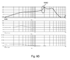
- the top graph shows a frequency response graph from 100 Hz to 10 kHz in decibels.
- the middle graph shows the same frequency response graph in magnitude of volts/current.
- the bottom graph shows the same frequency response graph in Volts (RMS).
- the back enclosure 70B and opening 522 provide a back resonator for speaker 16A which assists in equalizing high frequency signals (e.g. signals over about 2 kHz) for speaker 16A to about 2 kHz to equalize the ear resonance.
- FIG. 9B three graphs corresponding to those in Fig. 9A are shown, illustrating that as the cross-sectioned area of opening 522 in port 510 gets larger, the resonant frequency of the back resonator increases. Note the peak signal at 900B in the top graph between 4 kHz and 5 kHz.
- FIG. 9C three graphs corresponding to those in Fig. 9A are shown, illustrating that as the length of port 510 increases, the resonant frequency decreases. Note the characteristics of signal at 900C in the top graph between 1 kHz and 2 kHz.
- Fig. 9D three graphs corresponding to those in Fig. 9A are shown, illustrating that as the volume of main enclosure 508 increases, the resonant frequency of the back volume resonator decreases. Note the peak signal at 900D in the top graph at about 2 kHz.
- FIG. 10 a schematic representation of either of back enclosure 70B or 70BB with speaker 16A is shown.
- bottom portion 506 of speaker 16A is shown as being enclosed in a volume of air 526 bounded by back enclosure 70B.
- This volume of air 526 is connected to port 510 which connects to a deemed infinite volume of air 1000.
- the deemed infinite volume of air may be outside device 10.
- the deemed infinite amount of air is understood to be, relative to the volume of air in back enclosure 70B or 70BB a volume of air that is effectively, if frequency response calculations are made, an amount of air that is effectively equivalent to being an infinite amount of air compared to the volume of air in port 510.
- the amount of air may be several times in magnitude in volume greater than the volume of air in port 510.
- enclosure 70A, 70AA, back enclosure 70B, 70BB and speaker 16A may be modelled using analogous "circuits" using electro-mechanical components that provide an analog in an (electrical) circuit to the components in the acoustic system.
- a block diagram 1100 of an electrical circuit is an analogous electrical circuit to an exemplary acoustic circuit of the back enclosure 70B or 70BB and the back of speaker 16A.
- the back portion 506 of speaker 16A is shown as a sound source 1102 which is connected in parallel to a back volume 526 of back enclosure 70B or 70BB, which is modelled as a capacitor 1104.
- Port 510 is modelled as a resistor / inductor 1106 and is connected in series to an acoustic resistance control module 1108 representing may be an acoustic mesh.
- the ground 1110 is provided by the infinite volume of air at the end of port 510.
- the acoustic resistance of the back volume provided by resistor 1106 representing may be an acoustic mesh.
- the acoustic control module 1108 may be used to modify and tune the sensitivity of a resonance of the speaker 16A to limit maximum excursion for a given input voltage.
- the back enclosure volume 526 and dimensions of opening 522 in port 510 may also be changed to equalize the frequency in the high frequency range as shown in Figs. 9A-9E and described earlier. The effect may be controlled with resistance value of the acoustic control module 1108.
- a small band application of front volume resonator has a resonance of approximately 3.5 kHz.
- a sensitivity drop of approximately 2.5 kHz may be allowable for many applications.
- Back enclosure 70B or 70BB may be used to equalize the frequency response in a frequency range of between about 2 kHz and 3.5 kHz and may be used to equalize the frequency response in a high leak application.
- the frequency response of back enclosure 70B or 70BB may be aligned to a frequency which is slightly higher than the ear resonance.
- the effect may be controlled with resistance value of the acoustic control module 1008. Referring to Fig. 9E , it can be seen that the resistance value is a factor in controlling the Q factor of the resonator. Note the peak signal at 900E in the top graph between 2 kHz and 3 kHz.
- these effects may be combined by adjusting frequency response provided by back enclosure 70B or 70BB to be approximately 2 kHz in small bandwidth applications with low resistance values for resistor/inductor 1006 and acoustic control module 1008. Also, the effects may be combined by adjusting the frequency response provided by back enclosure 70B or 70BB to be in a similar frequency range as the front enclosure 70A or 70AA with low resistance values for resistor/inductor 906 and acoustic control module 1008.
- frequency response modification provided by front and back enclosures 70A, 70AA, 70B and 70BB may be aligned to such that speaker 16A has tuned operating characteristics around the frequency range of between approximately 5 and 6 kHz.
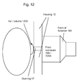
- FIG. 12 a schematic representation of the front enclosure 70A or 70AA with speaker 16A is shown.
- device 10 is placed against the user's ear, with opening 17 for speaker 16A in housing 12 placed against the user's ear.
- opening 17 for speaker 16A in housing 12 placed against the user's ear.
- the response characteristics of speaker 16A are shaped by the volume of air formed by front enclosure 70A or 70AA, aperture 504 and the interior volume 1200 of the user's ear.
- the interior volume 1200 is effectively not in communication with the volume of air that is in communication with the air around the distal end of port 510.
- block diagram 1300 shows an electrical circuit which provides an electrical circuit which provides a electrical circuit model of the acoustic properties of either of front enclosure 70A or 70AA and the front of speaker 16A.
- the front side of speaker 16A is shown as a power source and is connected in parallel with the front volume provided by front enclosure 70A, shown as a capacitor.
- the front volume provided by the aperture 504 is modelled as a resistor / inductor element and is connected to the interior volume of the user's ear, which is modelled as an impedance element.
- an enclosure for a speaker may be provided on the same side of the PCB on which the speaker mounts, incorporating any one or more of the enclosure features, apertures or other acoustic properties described above.
- a resonator for a transducer of an electronic device.
- a resonator may be configured as a speaker for use in an acoustic system or sub-system of an electronic device.
- the acoustic system may comprise a speaker; a first enclosure having a first opening to receive a back end of said transducer and a second opening; a port connected to the first enclosure through said second opening of said enclosure, said port having a first end, a second end, an interior channel and a third opening in the second end; and a second enclosure to cover a front portion of said transducer, said second enclosure including at least one aperture to air outside of said device to be in communication with said front of said transducer, wherein when said speaker is mounted into said first enclosure, a first volume between said transducer and said first enclosure is formed which is in communication with air surrounding said second end of said port through said interior channel of said port.
- a range of values will be understood to be valid for that dimension. For example, for a dimension stated as an approximate value, a range of about 20% larger and 20% smaller than the stated value may be used. Dimensions of features are illustrative of embodiments and are not limiting unless noted.
- cross-hatching of an element is not generally provided where a cross-section of the element is shown, in order to assist with clarity of same.
Landscapes
- Health & Medical Sciences (AREA)
- Otolaryngology (AREA)
- Physics & Mathematics (AREA)
- Engineering & Computer Science (AREA)
- Acoustics & Sound (AREA)
- Signal Processing (AREA)
- Details Of Audible-Bandwidth Transducers (AREA)
- Telephone Set Structure (AREA)
- Obtaining Desirable Characteristics In Audible-Bandwidth Transducers (AREA)
Priority Applications (1)
| Application Number | Priority Date | Filing Date | Title |
|---|---|---|---|
| EP11187579.5A EP2416591B1 (de) | 2008-10-07 | 2009-10-07 | Resonatorsystem für einen Lautsprecher einer elektronischen Vorrichtung |
Applications Claiming Priority (1)
| Application Number | Priority Date | Filing Date | Title |
|---|---|---|---|
| US10335608P | 2008-10-07 | 2008-10-07 |
Related Child Applications (2)
| Application Number | Title | Priority Date | Filing Date |
|---|---|---|---|
| EP11187579.5A Division EP2416591B1 (de) | 2008-10-07 | 2009-10-07 | Resonatorsystem für einen Lautsprecher einer elektronischen Vorrichtung |
| EP11187579.5 Division-Into | 2011-11-02 |
Publications (2)
| Publication Number | Publication Date |
|---|---|
| EP2175668A1 true EP2175668A1 (de) | 2010-04-14 |
| EP2175668B1 EP2175668B1 (de) | 2012-01-18 |
Family
ID=42025831
Family Applications (2)
| Application Number | Title | Priority Date | Filing Date |
|---|---|---|---|
| EP09172485A Active EP2175668B1 (de) | 2008-10-07 | 2009-10-07 | Resonatorsystem für einen Sprecher einer elektronischen Vorrichtung |
| EP11187579.5A Active EP2416591B1 (de) | 2008-10-07 | 2009-10-07 | Resonatorsystem für einen Lautsprecher einer elektronischen Vorrichtung |
Family Applications After (1)
| Application Number | Title | Priority Date | Filing Date |
|---|---|---|---|
| EP11187579.5A Active EP2416591B1 (de) | 2008-10-07 | 2009-10-07 | Resonatorsystem für einen Lautsprecher einer elektronischen Vorrichtung |
Country Status (5)
| Country | Link |
|---|---|
| US (2) | US8320599B2 (de) |
| EP (2) | EP2175668B1 (de) |
| AT (1) | ATE542373T1 (de) |
| CA (1) | CA2681840C (de) |
| WO (1) | WO2010040210A1 (de) |
Cited By (1)
| Publication number | Priority date | Publication date | Assignee | Title |
|---|---|---|---|---|
| WO2016129987A1 (en) * | 2015-02-11 | 2016-08-18 | Knowles Ipc (M) Sdn. Bhd. | Electrodynamic transducer in ultrasonic mode |
Families Citing this family (10)
| Publication number | Priority date | Publication date | Assignee | Title |
|---|---|---|---|---|
| US8520883B2 (en) * | 2010-07-21 | 2013-08-27 | Dennis A. Tracy | Articulating speaker assembly providing for pivotal adjustment of connected first and second midrange members |
| US20120274647A1 (en) * | 2011-04-26 | 2012-11-01 | Qualcomm Mems Technologies, Inc. | Piezoelectric resonators and fabrication processes |
| US8816567B2 (en) | 2011-07-19 | 2014-08-26 | Qualcomm Mems Technologies, Inc. | Piezoelectric laterally vibrating resonator structure geometries for spurious frequency suppression |
| CN103313154A (zh) * | 2012-03-09 | 2013-09-18 | 鸿富锦精密工业(深圳)有限公司 | 防止扬声器产生异音的电子装置 |
| US8588864B1 (en) * | 2012-04-30 | 2013-11-19 | Motorola Mobility Llc | Electronic device with an improved acoustic mesh system |
| USD715796S1 (en) * | 2012-04-30 | 2014-10-21 | Promethean Limited | Handset for interactive learning |
| US9804003B2 (en) * | 2012-10-23 | 2017-10-31 | Apple Inc. | Electronic devices with environmental sensors |
| USD684556S1 (en) * | 2012-11-30 | 2013-06-18 | Research In Motion Limited | Handheld electronic device |
| US9805070B2 (en) | 2013-07-09 | 2017-10-31 | Oracle International Corporation | Dynamic migration script management |
| CN104754441A (zh) * | 2013-12-31 | 2015-07-01 | 深圳富泰宏精密工业有限公司 | 扬声器组件和应用该扬声器组件的电子装置 |
Citations (2)
| Publication number | Priority date | Publication date | Assignee | Title |
|---|---|---|---|---|
| WO1997047117A1 (en) * | 1996-06-06 | 1997-12-11 | Northern Telecom Limited | Communications terminal having a single transducer for handset and handsfree receive functionality |
| WO2007000484A1 (en) * | 2005-06-29 | 2007-01-04 | Nokia Corporation | A speaker apparatus in a wireless communication device |
Family Cites Families (5)
| Publication number | Priority date | Publication date | Assignee | Title |
|---|---|---|---|---|
| US7218747B2 (en) | 2003-12-05 | 2007-05-15 | Nick Huffman | Externally ported loudspeaker enclosure |
| US7409058B2 (en) * | 2004-06-01 | 2008-08-05 | Research In Motion Limited | Display cover for a communication device |
| WO2008033579A2 (en) | 2006-09-12 | 2008-03-20 | Portable Sound Laboratories, Inc. | Speaker system for portable multimedia player |
| ATE500692T1 (de) * | 2008-05-02 | 2011-03-15 | Research In Motion Ltd | Gehäuse und gehäusesystem für einen lautsprecher einer elektronischen vorrichtung |
| US8891802B2 (en) * | 2008-05-02 | 2014-11-18 | Blackberry Limited | Enclosure and enclosure system for a speaker of an electronic device |
-
2009
- 2009-10-06 US US12/574,375 patent/US8320599B2/en active Active
- 2009-10-06 WO PCT/CA2009/001414 patent/WO2010040210A1/en not_active Ceased
- 2009-10-07 EP EP09172485A patent/EP2175668B1/de active Active
- 2009-10-07 AT AT09172485T patent/ATE542373T1/de active
- 2009-10-07 CA CA2681840A patent/CA2681840C/en active Active
- 2009-10-07 EP EP11187579.5A patent/EP2416591B1/de active Active
-
2012
- 2012-10-17 US US13/654,012 patent/US8750549B2/en active Active
Patent Citations (2)
| Publication number | Priority date | Publication date | Assignee | Title |
|---|---|---|---|---|
| WO1997047117A1 (en) * | 1996-06-06 | 1997-12-11 | Northern Telecom Limited | Communications terminal having a single transducer for handset and handsfree receive functionality |
| WO2007000484A1 (en) * | 2005-06-29 | 2007-01-04 | Nokia Corporation | A speaker apparatus in a wireless communication device |
Cited By (1)
| Publication number | Priority date | Publication date | Assignee | Title |
|---|---|---|---|---|
| WO2016129987A1 (en) * | 2015-02-11 | 2016-08-18 | Knowles Ipc (M) Sdn. Bhd. | Electrodynamic transducer in ultrasonic mode |
Also Published As
| Publication number | Publication date |
|---|---|
| US8750549B2 (en) | 2014-06-10 |
| EP2416591B1 (de) | 2014-03-26 |
| US8320599B2 (en) | 2012-11-27 |
| ATE542373T1 (de) | 2012-02-15 |
| WO2010040210A1 (en) | 2010-04-15 |
| CA2681840C (en) | 2015-12-22 |
| US20130094688A1 (en) | 2013-04-18 |
| EP2416591A1 (de) | 2012-02-08 |
| CA2681840A1 (en) | 2010-04-07 |
| US20100086163A1 (en) | 2010-04-08 |
| EP2175668B1 (de) | 2012-01-18 |
Similar Documents
| Publication | Publication Date | Title |
|---|---|---|
| EP2175668B1 (de) | Resonatorsystem für einen Sprecher einer elektronischen Vorrichtung | |
| US8891802B2 (en) | Enclosure and enclosure system for a speaker of an electronic device | |
| EP2293593B1 (de) | Gehäuse und Gehäusesystem für einen Lautsprecher einer elektronischen Vorrichtung | |
| EP2238769B1 (de) | Akustische neukonfigurationsvorrichtungen und verfahren | |
| US6785395B1 (en) | Speaker configuration for a portable electronic device | |
| TWI244303B (en) | Resonation chambers within a cell phone | |
| US8094856B2 (en) | Microphone coupler for a communication device | |
| US20090232298A1 (en) | Microphone coupler system for a communication device | |
| CN114257929B (zh) | 用于电子设备的冲击压力抑制阀 | |
| EP2661100A1 (de) | Elektronische vorrichtung | |
| EP1629686B1 (de) | Mobiles endgerät mit einer umgekehrt montierten mikrosprecherkonstruktion und verfahren zur bereitstellung einer mikrosprecherkonstruktion für mobile endgeräte | |
| EP1547432A1 (de) | Doppelresonator-mikrolautsprecherbaugruppen und verfahren zu ihrer abstimmung | |
| WO2009079033A1 (en) | Printed circuit board for a flat-panel speaker | |
| CN102651835B (zh) | 调整音质的方法及电子装置 | |
| JP3984968B2 (ja) | 電子通信機器 | |
| CN1489362A (zh) | 用于包括有扬声器和耳机的无线通信终端的结构布置 | |
| GB2504723A (en) | Waveguide housing for a portable device with built-in passive amplification of the loudspeaker | |
| US20150189412A1 (en) | Sound transducer acoustic back cavity system | |
| EP1955573B1 (de) | Lautsprechergehäuse | |
| EP1748673B1 (de) | Tragbares elektronisches Gerät mit versetzten Ausgabeöffnungen | |
| EP1780989A1 (de) | Mikrofonkoppler für ein Kommunikationsgerät | |
| WO2019190559A1 (en) | Microphone units with multiple openings |
Legal Events
| Date | Code | Title | Description |
|---|---|---|---|
| PUAI | Public reference made under article 153(3) epc to a published international application that has entered the european phase |
Free format text: ORIGINAL CODE: 0009012 |
|
| 17P | Request for examination filed |
Effective date: 20091007 |
|
| AK | Designated contracting states |
Kind code of ref document: A1 Designated state(s): AT BE BG CH CY CZ DE DK EE ES FI FR GB GR HR HU IE IS IT LI LT LU LV MC MK MT NL NO PL PT RO SE SI SK SM TR |
|
| AX | Request for extension of the european patent |
Extension state: AL BA RS |
|
| RAP1 | Party data changed (applicant data changed or rights of an application transferred) |
Owner name: RESEARCH IN MOTION LIMITED |
|
| 17Q | First examination report despatched |
Effective date: 20100706 |
|
| GRAP | Despatch of communication of intention to grant a patent |
Free format text: ORIGINAL CODE: EPIDOSNIGR1 |
|
| GRAS | Grant fee paid |
Free format text: ORIGINAL CODE: EPIDOSNIGR3 |
|
| GRAA | (expected) grant |
Free format text: ORIGINAL CODE: 0009210 |
|
| AK | Designated contracting states |
Kind code of ref document: B1 Designated state(s): AT BE BG CH CY CZ DE DK EE ES FI FR GB GR HR HU IE IS IT LI LT LU LV MC MK MT NL NO PL PT RO SE SI SK SM TR |
|
| REG | Reference to a national code |
Ref country code: GB Ref legal event code: FG4D |
|
| REG | Reference to a national code |
Ref country code: CH Ref legal event code: EP |
|
| REG | Reference to a national code |
Ref country code: IE Ref legal event code: FG4D Ref country code: AT Ref legal event code: REF Ref document number: 542373 Country of ref document: AT Kind code of ref document: T Effective date: 20120215 |
|
| REG | Reference to a national code |
Ref country code: DE Ref legal event code: R096 Ref document number: 602009004714 Country of ref document: DE Effective date: 20120315 |
|
| REG | Reference to a national code |
Ref country code: NL Ref legal event code: VDEP Effective date: 20120118 |
|
| LTIE | Lt: invalidation of european patent or patent extension |
Effective date: 20120118 |
|
| PG25 | Lapsed in a contracting state [announced via postgrant information from national office to epo] |
Ref country code: BE Free format text: LAPSE BECAUSE OF FAILURE TO SUBMIT A TRANSLATION OF THE DESCRIPTION OR TO PAY THE FEE WITHIN THE PRESCRIBED TIME-LIMIT Effective date: 20120118 Ref country code: LT Free format text: LAPSE BECAUSE OF FAILURE TO SUBMIT A TRANSLATION OF THE DESCRIPTION OR TO PAY THE FEE WITHIN THE PRESCRIBED TIME-LIMIT Effective date: 20120118 Ref country code: IS Free format text: LAPSE BECAUSE OF FAILURE TO SUBMIT A TRANSLATION OF THE DESCRIPTION OR TO PAY THE FEE WITHIN THE PRESCRIBED TIME-LIMIT Effective date: 20120518 Ref country code: HR Free format text: LAPSE BECAUSE OF FAILURE TO SUBMIT A TRANSLATION OF THE DESCRIPTION OR TO PAY THE FEE WITHIN THE PRESCRIBED TIME-LIMIT Effective date: 20120118 Ref country code: BG Free format text: LAPSE BECAUSE OF FAILURE TO SUBMIT A TRANSLATION OF THE DESCRIPTION OR TO PAY THE FEE WITHIN THE PRESCRIBED TIME-LIMIT Effective date: 20120418 Ref country code: NL Free format text: LAPSE BECAUSE OF FAILURE TO SUBMIT A TRANSLATION OF THE DESCRIPTION OR TO PAY THE FEE WITHIN THE PRESCRIBED TIME-LIMIT Effective date: 20120118 Ref country code: NO Free format text: LAPSE BECAUSE OF FAILURE TO SUBMIT A TRANSLATION OF THE DESCRIPTION OR TO PAY THE FEE WITHIN THE PRESCRIBED TIME-LIMIT Effective date: 20120418 |
|
| PG25 | Lapsed in a contracting state [announced via postgrant information from national office to epo] |
Ref country code: PL Free format text: LAPSE BECAUSE OF FAILURE TO SUBMIT A TRANSLATION OF THE DESCRIPTION OR TO PAY THE FEE WITHIN THE PRESCRIBED TIME-LIMIT Effective date: 20120118 Ref country code: FI Free format text: LAPSE BECAUSE OF FAILURE TO SUBMIT A TRANSLATION OF THE DESCRIPTION OR TO PAY THE FEE WITHIN THE PRESCRIBED TIME-LIMIT Effective date: 20120118 Ref country code: LV Free format text: LAPSE BECAUSE OF FAILURE TO SUBMIT A TRANSLATION OF THE DESCRIPTION OR TO PAY THE FEE WITHIN THE PRESCRIBED TIME-LIMIT Effective date: 20120118 Ref country code: GR Free format text: LAPSE BECAUSE OF FAILURE TO SUBMIT A TRANSLATION OF THE DESCRIPTION OR TO PAY THE FEE WITHIN THE PRESCRIBED TIME-LIMIT Effective date: 20120419 Ref country code: PT Free format text: LAPSE BECAUSE OF FAILURE TO SUBMIT A TRANSLATION OF THE DESCRIPTION OR TO PAY THE FEE WITHIN THE PRESCRIBED TIME-LIMIT Effective date: 20120518 |
|
| REG | Reference to a national code |
Ref country code: AT Ref legal event code: MK05 Ref document number: 542373 Country of ref document: AT Kind code of ref document: T Effective date: 20120118 |
|
| PG25 | Lapsed in a contracting state [announced via postgrant information from national office to epo] |
Ref country code: CY Free format text: LAPSE BECAUSE OF FAILURE TO SUBMIT A TRANSLATION OF THE DESCRIPTION OR TO PAY THE FEE WITHIN THE PRESCRIBED TIME-LIMIT Effective date: 20120118 |
|
| PG25 | Lapsed in a contracting state [announced via postgrant information from national office to epo] |
Ref country code: CZ Free format text: LAPSE BECAUSE OF FAILURE TO SUBMIT A TRANSLATION OF THE DESCRIPTION OR TO PAY THE FEE WITHIN THE PRESCRIBED TIME-LIMIT Effective date: 20120118 Ref country code: RO Free format text: LAPSE BECAUSE OF FAILURE TO SUBMIT A TRANSLATION OF THE DESCRIPTION OR TO PAY THE FEE WITHIN THE PRESCRIBED TIME-LIMIT Effective date: 20120118 Ref country code: DK Free format text: LAPSE BECAUSE OF FAILURE TO SUBMIT A TRANSLATION OF THE DESCRIPTION OR TO PAY THE FEE WITHIN THE PRESCRIBED TIME-LIMIT Effective date: 20120118 Ref country code: EE Free format text: LAPSE BECAUSE OF FAILURE TO SUBMIT A TRANSLATION OF THE DESCRIPTION OR TO PAY THE FEE WITHIN THE PRESCRIBED TIME-LIMIT Effective date: 20120118 Ref country code: SE Free format text: LAPSE BECAUSE OF FAILURE TO SUBMIT A TRANSLATION OF THE DESCRIPTION OR TO PAY THE FEE WITHIN THE PRESCRIBED TIME-LIMIT Effective date: 20120118 Ref country code: SI Free format text: LAPSE BECAUSE OF FAILURE TO SUBMIT A TRANSLATION OF THE DESCRIPTION OR TO PAY THE FEE WITHIN THE PRESCRIBED TIME-LIMIT Effective date: 20120118 |
|
| PLBE | No opposition filed within time limit |
Free format text: ORIGINAL CODE: 0009261 |
|
| STAA | Information on the status of an ep patent application or granted ep patent |
Free format text: STATUS: NO OPPOSITION FILED WITHIN TIME LIMIT |
|
| PG25 | Lapsed in a contracting state [announced via postgrant information from national office to epo] |
Ref country code: IT Free format text: LAPSE BECAUSE OF FAILURE TO SUBMIT A TRANSLATION OF THE DESCRIPTION OR TO PAY THE FEE WITHIN THE PRESCRIBED TIME-LIMIT Effective date: 20120118 Ref country code: SK Free format text: LAPSE BECAUSE OF FAILURE TO SUBMIT A TRANSLATION OF THE DESCRIPTION OR TO PAY THE FEE WITHIN THE PRESCRIBED TIME-LIMIT Effective date: 20120118 |
|
| 26N | No opposition filed |
Effective date: 20121019 |
|
| PG25 | Lapsed in a contracting state [announced via postgrant information from national office to epo] |
Ref country code: AT Free format text: LAPSE BECAUSE OF FAILURE TO SUBMIT A TRANSLATION OF THE DESCRIPTION OR TO PAY THE FEE WITHIN THE PRESCRIBED TIME-LIMIT Effective date: 20120118 |
|
| REG | Reference to a national code |
Ref country code: DE Ref legal event code: R097 Ref document number: 602009004714 Country of ref document: DE Effective date: 20121019 |
|
| PG25 | Lapsed in a contracting state [announced via postgrant information from national office to epo] |
Ref country code: ES Free format text: LAPSE BECAUSE OF FAILURE TO SUBMIT A TRANSLATION OF THE DESCRIPTION OR TO PAY THE FEE WITHIN THE PRESCRIBED TIME-LIMIT Effective date: 20120429 |
|
| PG25 | Lapsed in a contracting state [announced via postgrant information from national office to epo] |
Ref country code: MC Free format text: LAPSE BECAUSE OF NON-PAYMENT OF DUE FEES Effective date: 20121031 |
|
| REG | Reference to a national code |
Ref country code: IE Ref legal event code: MM4A |
|
| PG25 | Lapsed in a contracting state [announced via postgrant information from national office to epo] |
Ref country code: IE Free format text: LAPSE BECAUSE OF NON-PAYMENT OF DUE FEES Effective date: 20121007 |
|
| PG25 | Lapsed in a contracting state [announced via postgrant information from national office to epo] |
Ref country code: MT Free format text: LAPSE BECAUSE OF FAILURE TO SUBMIT A TRANSLATION OF THE DESCRIPTION OR TO PAY THE FEE WITHIN THE PRESCRIBED TIME-LIMIT Effective date: 20120118 |
|
| PG25 | Lapsed in a contracting state [announced via postgrant information from national office to epo] |
Ref country code: TR Free format text: LAPSE BECAUSE OF FAILURE TO SUBMIT A TRANSLATION OF THE DESCRIPTION OR TO PAY THE FEE WITHIN THE PRESCRIBED TIME-LIMIT Effective date: 20120118 |
|
| PG25 | Lapsed in a contracting state [announced via postgrant information from national office to epo] |
Ref country code: SM Free format text: LAPSE BECAUSE OF FAILURE TO SUBMIT A TRANSLATION OF THE DESCRIPTION OR TO PAY THE FEE WITHIN THE PRESCRIBED TIME-LIMIT Effective date: 20120118 Ref country code: LU Free format text: LAPSE BECAUSE OF NON-PAYMENT OF DUE FEES Effective date: 20121007 |
|
| REG | Reference to a national code |
Ref country code: CH Ref legal event code: PL |
|
| PG25 | Lapsed in a contracting state [announced via postgrant information from national office to epo] |
Ref country code: HU Free format text: LAPSE BECAUSE OF FAILURE TO SUBMIT A TRANSLATION OF THE DESCRIPTION OR TO PAY THE FEE WITHIN THE PRESCRIBED TIME-LIMIT Effective date: 20091007 Ref country code: LI Free format text: LAPSE BECAUSE OF NON-PAYMENT OF DUE FEES Effective date: 20131031 Ref country code: CH Free format text: LAPSE BECAUSE OF NON-PAYMENT OF DUE FEES Effective date: 20131031 |
|
| REG | Reference to a national code |
Ref country code: DE Ref legal event code: R082 Ref document number: 602009004714 Country of ref document: DE Representative=s name: MERH-IP MATIAS ERNY REICHL HOFFMANN, DE |
|
| REG | Reference to a national code |
Ref country code: DE Ref legal event code: R081 Ref document number: 602009004714 Country of ref document: DE Owner name: BLACKBERRY LIMITED, WATERLOO, CA Free format text: FORMER OWNER: RESEARCH IN MOTION LIMITED, WATERLOO, ONTARIO, CA Effective date: 20140926 Ref country code: DE Ref legal event code: R082 Ref document number: 602009004714 Country of ref document: DE Representative=s name: MERH-IP MATIAS ERNY REICHL HOFFMANN, DE Effective date: 20140926 Ref country code: DE Ref legal event code: R082 Ref document number: 602009004714 Country of ref document: DE Representative=s name: MERH-IP MATIAS ERNY REICHL HOFFMANN PATENTANWA, DE Effective date: 20140926 |
|
| PG25 | Lapsed in a contracting state [announced via postgrant information from national office to epo] |
Ref country code: MK Free format text: LAPSE BECAUSE OF FAILURE TO SUBMIT A TRANSLATION OF THE DESCRIPTION OR TO PAY THE FEE WITHIN THE PRESCRIBED TIME-LIMIT Effective date: 20120118 |
|
| REG | Reference to a national code |
Ref country code: FR Ref legal event code: PLFP Year of fee payment: 7 |
|
| REG | Reference to a national code |
Ref country code: FR Ref legal event code: PLFP Year of fee payment: 8 |
|
| REG | Reference to a national code |
Ref country code: FR Ref legal event code: PLFP Year of fee payment: 9 |
|
| REG | Reference to a national code |
Ref country code: FR Ref legal event code: PLFP Year of fee payment: 10 |
|
| REG | Reference to a national code |
Ref country code: DE Ref legal event code: R082 Ref document number: 602009004714 Country of ref document: DE Ref country code: DE Ref legal event code: R081 Ref document number: 602009004714 Country of ref document: DE Owner name: MALIKIE INNOVATIONS LTD., IE Free format text: FORMER OWNER: BLACKBERRY LIMITED, WATERLOO, ONTARIO, CA |
|
| PGFP | Annual fee paid to national office [announced via postgrant information from national office to epo] |
Ref country code: GB Payment date: 20251223 Year of fee payment: 17 |
|
| PGFP | Annual fee paid to national office [announced via postgrant information from national office to epo] |
Ref country code: FR Payment date: 20251222 Year of fee payment: 17 |
|
| PGFP | Annual fee paid to national office [announced via postgrant information from national office to epo] |
Ref country code: DE Payment date: 20251229 Year of fee payment: 17 |