EP2175806B1 - Implant intraoculaire souple a haptique circulaire - Google Patents
Implant intraoculaire souple a haptique circulaire Download PDFInfo
- Publication number
- EP2175806B1 EP2175806B1 EP08826543.4A EP08826543A EP2175806B1 EP 2175806 B1 EP2175806 B1 EP 2175806B1 EP 08826543 A EP08826543 A EP 08826543A EP 2175806 B1 EP2175806 B1 EP 2175806B1
- Authority
- EP
- European Patent Office
- Prior art keywords
- optical
- optical axis
- intraocular implant
- contact elements
- connection
- Prior art date
- Legal status (The legal status is an assumption and is not a legal conclusion. Google has not performed a legal analysis and makes no representation as to the accuracy of the status listed.)
- Not-in-force
Links
- 239000007943 implant Substances 0.000 title claims description 54
- 230000003287 optical effect Effects 0.000 claims description 69
- 230000000694 effects Effects 0.000 claims description 5
- 230000003467 diminishing effect Effects 0.000 claims 1
- 239000000463 material Substances 0.000 description 8
- 238000006073 displacement reaction Methods 0.000 description 6
- 230000007423 decrease Effects 0.000 description 3
- 239000000017 hydrogel Substances 0.000 description 3
- NIXOWILDQLNWCW-UHFFFAOYSA-N acrylic acid group Chemical group C(C=C)(=O)O NIXOWILDQLNWCW-UHFFFAOYSA-N 0.000 description 2
- 230000008602 contraction Effects 0.000 description 2
- 230000002209 hydrophobic effect Effects 0.000 description 2
- 230000001717 pathogenic effect Effects 0.000 description 2
- 229920003229 poly(methyl methacrylate) Polymers 0.000 description 2
- 239000004926 polymethyl methacrylate Substances 0.000 description 2
- 230000035755 proliferation Effects 0.000 description 2
- 208000008516 Capsule Opacification Diseases 0.000 description 1
- 208000002177 Cataract Diseases 0.000 description 1
- 229920000297 Rayon Polymers 0.000 description 1
- 239000000470 constituent Substances 0.000 description 1
- 238000012423 maintenance Methods 0.000 description 1
- 239000002964 rayon Substances 0.000 description 1
Images
Classifications
-
- A—HUMAN NECESSITIES
- A61—MEDICAL OR VETERINARY SCIENCE; HYGIENE
- A61F—FILTERS IMPLANTABLE INTO BLOOD VESSELS; PROSTHESES; DEVICES PROVIDING PATENCY TO, OR PREVENTING COLLAPSING OF, TUBULAR STRUCTURES OF THE BODY, e.g. STENTS; ORTHOPAEDIC, NURSING OR CONTRACEPTIVE DEVICES; FOMENTATION; TREATMENT OR PROTECTION OF EYES OR EARS; BANDAGES, DRESSINGS OR ABSORBENT PADS; FIRST-AID KITS
- A61F2/00—Filters implantable into blood vessels; Prostheses, i.e. artificial substitutes or replacements for parts of the body; Appliances for connecting them with the body; Devices providing patency to, or preventing collapsing of, tubular structures of the body, e.g. stents
- A61F2/02—Prostheses implantable into the body
- A61F2/14—Eye parts, e.g. lenses or corneal implants; Artificial eyes
- A61F2/16—Intraocular lenses
- A61F2/1613—Intraocular lenses having special lens configurations, e.g. multipart lenses; having particular optical properties, e.g. pseudo-accommodative lenses, lenses having aberration corrections, diffractive lenses, lenses for variably absorbing electromagnetic radiation, lenses having variable focus
-
- A—HUMAN NECESSITIES
- A61—MEDICAL OR VETERINARY SCIENCE; HYGIENE
- A61F—FILTERS IMPLANTABLE INTO BLOOD VESSELS; PROSTHESES; DEVICES PROVIDING PATENCY TO, OR PREVENTING COLLAPSING OF, TUBULAR STRUCTURES OF THE BODY, e.g. STENTS; ORTHOPAEDIC, NURSING OR CONTRACEPTIVE DEVICES; FOMENTATION; TREATMENT OR PROTECTION OF EYES OR EARS; BANDAGES, DRESSINGS OR ABSORBENT PADS; FIRST-AID KITS
- A61F2/00—Filters implantable into blood vessels; Prostheses, i.e. artificial substitutes or replacements for parts of the body; Appliances for connecting them with the body; Devices providing patency to, or preventing collapsing of, tubular structures of the body, e.g. stents
- A61F2/02—Prostheses implantable into the body
- A61F2/14—Eye parts, e.g. lenses or corneal implants; Artificial eyes
- A61F2/16—Intraocular lenses
- A61F2/1613—Intraocular lenses having special lens configurations, e.g. multipart lenses; having particular optical properties, e.g. pseudo-accommodative lenses, lenses having aberration corrections, diffractive lenses, lenses for variably absorbing electromagnetic radiation, lenses having variable focus
- A61F2/1624—Intraocular lenses having special lens configurations, e.g. multipart lenses; having particular optical properties, e.g. pseudo-accommodative lenses, lenses having aberration corrections, diffractive lenses, lenses for variably absorbing electromagnetic radiation, lenses having variable focus having adjustable focus; power activated variable focus means, e.g. mechanically or electrically by the ciliary muscle or from the outside
- A61F2/1629—Intraocular lenses having special lens configurations, e.g. multipart lenses; having particular optical properties, e.g. pseudo-accommodative lenses, lenses having aberration corrections, diffractive lenses, lenses for variably absorbing electromagnetic radiation, lenses having variable focus having adjustable focus; power activated variable focus means, e.g. mechanically or electrically by the ciliary muscle or from the outside for changing longitudinal position, i.e. along the visual axis when implanted
-
- A—HUMAN NECESSITIES
- A61—MEDICAL OR VETERINARY SCIENCE; HYGIENE
- A61F—FILTERS IMPLANTABLE INTO BLOOD VESSELS; PROSTHESES; DEVICES PROVIDING PATENCY TO, OR PREVENTING COLLAPSING OF, TUBULAR STRUCTURES OF THE BODY, e.g. STENTS; ORTHOPAEDIC, NURSING OR CONTRACEPTIVE DEVICES; FOMENTATION; TREATMENT OR PROTECTION OF EYES OR EARS; BANDAGES, DRESSINGS OR ABSORBENT PADS; FIRST-AID KITS
- A61F2/00—Filters implantable into blood vessels; Prostheses, i.e. artificial substitutes or replacements for parts of the body; Appliances for connecting them with the body; Devices providing patency to, or preventing collapsing of, tubular structures of the body, e.g. stents
- A61F2/02—Prostheses implantable into the body
- A61F2/14—Eye parts, e.g. lenses or corneal implants; Artificial eyes
- A61F2/16—Intraocular lenses
- A61F2002/1681—Intraocular lenses having supporting structure for lens, e.g. haptics
Definitions
- the present invention relates to a flexible intraocular implant circular haptic.
- the intraocular implants are constituted by two essential parts which are on the one hand, an optical part constituting the corrector system of the vision of the implant and, on the other hand, a haptic part which serves to maintain the part optical centered in the eye and, in the particular case consider in the capsular bag of the eye after removal of the lens.
- the haptic part of the intraocular implant can take various forms, the main types of which are C-shaped or J-shaped haptic loops or a circular shape connected to the optical part by arms.
- the intraocular implant object of the invention relates to the latter type of haptic part.
- the intraocular implant once put in place in the eye, must of course perform the desired optical correction for the patient. This correction depends not only on the characteristics of the optical part but also on the position of the intraocular implant inside the eye.
- the implant maintains the position in the eye initially planned by the surgeon. However, it turns out that after the introduction of the implant in the capsular bag, it tends to decrease in diameter in the period following the implementation of the implant. This reduction in diameter can reach 10%.
- the document FR 2 841 122 describes an implant that may present the risks mentioned above.
- the document DE 37 22910 discloses an intraocular lens which comprises a haptic portion made of two loops connected to the periphery of the optical portion.
- the document FR 2 786 686 discloses an intraocular implant of flexible material comprising a haptic portion of closed annular shape.
- the document EP 592 813 also describes intraocular implants.
- An object of the present invention is therefore to provide an intraocular implant made of a flexible material which comprises a haptic part of generally circular shape which is deformed in such a way that under the effect of the reduction of the diameter of the capsular bag, it does not causes no significant displacement of the optical portion in the direction of its optical axis and no significant angulation of the optical axis of the implant relative to the optical axis of the eye.
- the optical part of the intraocular implant does not undergo a significant displacement in the direction of its optical axis and, given the symmetry of revolution of the haptic part, this deformation is regular and of revolution and therefore does not cause angulation of the optical axis of the optical part with respect to the optical axis of the eye.
- the intraocular implant is characterized in that the connecting arms and the connecting elements have a cross section much smaller than the cross section of the contact elements.
- each contact element comprises an edge substantially parallel to the optical axis and two respectively anterior and posterior faces, the edge making with at least one of said faces an angle less than 120 degrees. thus forming a ridge or square edge capable of exerting a significant localized pressure on said capsular bag.
- the contact elements and the connecting elements form a closed annular piece.
- the intraocular implant 10 is made from a so-called flexible material, typically a hydrophilic or hydrophobic acrylic, a particular example of which is the product marketed under the trademark Hydrogel.
- the implant is monobloc.
- the implant 10 is constituted by an optical portion 12 of generally circular shape having an edge 12a, an anterior diopter 12b and a posterior diopter 12c.
- the intraocular implant also comprises a haptic portion 14 constituted by an outer circular ring 16 constituted by n contact elements 18 having an outer edge 20 and n connecting elements 22 of curved shape interposed between two consecutive contact elements 18.
- n is equal to 4 which corresponds to an optimal solution.
- n could be different but in any case at least equal to 2.
- all the elements of this contact 18 correspond to the same circular arc length.
- the ring 16 constituting the bulk of the haptic portion is connected to the periphery 12a of the optical portion 12 by n arms 24.
- Each contact element 18 has the shape of a circular arc at rest centered on the optical center O of the optical part 12 or more precisely on its optical axis X, X '.
- the ends 18a and 18b of each contact element 18 are connected to the ends 22a or 22b of an adjacent connecting element 22.
- Each arm 24 has a first end 24a for connection to a contact element 18 in its central part and a second end 24b of connection to the periphery of the optical portion 12, these ends including fillets providing some stiffening at the two connections.
- the contact elements 18 have a cross section such that they are much more rigid than the connecting elements 22 at least in a plane parallel to the optical plane of the optical portion 12 of the intraocular implant.
- the thickness e of the arms 24 (in the direction of the axis X, X ') is much greater, at least twice, the width l of these same arms.
- the width l 'of each connecting element 22 is much smaller than its thickness e' .
- the arms 24 have a forward angulation a towards the anterior diopter 12b with respect to the optical plane PP 'of the optical part 12.
- the contact elements 18 have an angulation b towards the back relative to a plane QQ 'parallel to the optical plane PP'.
- the first angulation has arms relative to the optical plane ensures the maintenance of the posterior diopter 12c of the optical portion 12 against the posterior portion 40 of the capsular bag 42 as shown in FIG. figure 4 .
- the angulation b of the contact elements 18 ensures a thrust of the optical portion forward which stably maintains the optical portion 12 against the posterior wall 40 of the capsular bag as has been described.
- the contact elements 18 comprise an anterior face 26, a rear face 28 and a flange 30.
- the posterior faces 28 and the rim 30 are determined such that they constitute at least one edge or square edge 32 able to exert a significant local pressure on the capsular bag in the equatorial region to form what is often called a "square edge" as already explained this square edge is able to block the proliferation of pathogenic cells of the equatorial zone of the bag capsular to its posterior wall 40.
- the angle between the posterior face 28 and the rim 30 is less than 120 degrees to form the ridge. In the example shown, this angle is less than 90 degrees due to the angulation b of the contact elements 18.
- the connecting elements 22 have in a plane parallel to the optical plane a rigidity much lower than that of the contact elements 18.
- the stresses resulting from this contraction applied to the external edges of the contact elements 18 will cause the connection elements 22 to bend without changing the shape of the contact elements 18 so that the external diameter D 'defined by the outer edge of the contact elements 18 becomes equal to the reduced diameter of the capsular bag.
- connection zones 22 avoids exerting a backward thrust on the optical part 12 since, in addition, the arms 24 have a relatively high flexibility in directions substantially orthogonal to the optical axis XX 'of the optical part 12.
- the deformation of the arms 24 naturally follows the reduction of the external diameter D 'defined by the external edges of the contact elements 18.
- the external diameter D of the intraocular implant at rest is equal to 10.5 mm.
- the ring 16 can contract in such a way that an external diameter of the contracted haptic D of the order of 8 mm is obtained without significant displacement of the optical part 12 in the direction of the optical axis of the implant XX '.
- the diameter decreases by localized deformation of this ring are regular. Consequently, this reduction in diameter causes no significant angulation of the optical axis XX 'of the optical portion 12 relative to the natural optical axis of the eye XX'.
- the haptic part consists essentially of a ring in contact with the equatorial zone of the capsular bag, this ring comprising an alternation of substantially rigid arc-shaped portions whose ends are connected together by deformable connection zones in such a way that the diameter reduction of the ring is done in a localized manner in the flexible connection elements.
Landscapes
- Health & Medical Sciences (AREA)
- Ophthalmology & Optometry (AREA)
- Cardiology (AREA)
- Oral & Maxillofacial Surgery (AREA)
- Transplantation (AREA)
- Engineering & Computer Science (AREA)
- Biomedical Technology (AREA)
- Heart & Thoracic Surgery (AREA)
- Vascular Medicine (AREA)
- Life Sciences & Earth Sciences (AREA)
- Animal Behavior & Ethology (AREA)
- General Health & Medical Sciences (AREA)
- Public Health (AREA)
- Veterinary Medicine (AREA)
- Prostheses (AREA)
Description
- La présente invention a pour objet un implant intraoculaire souple à haptique circulaire.
- Comme cela est bien connu, deux types de matériaux peuvent être utilisés pour réaliser des implants intraoculaires :
- soit des matériaux dits rigides tels que le PMMA ; soit des matériaux dits souples tels que des matériaux acryliques hydrophiles ou hydrophobes dont un exemple est connu sous la marque Hydrogel. La présente invention concerne un implant réalisé avec ce deuxième type de matériau.
- Il est également connu que les implants intraoculaires sont constitués par deux parties essentielles qui sont d'une part, une partie optique constituant le système correcteur de la vision de l'implant et d'autre part, une partie haptique qui sert à maintenir la partie optique centrée dans l'oeil et, dans le cas particulier considérer dans le sac capsulaire de l'oeil après ablation du cristallin.
- La partie haptique de l'implant intraoculaire peut prendre différentes formes dont les principaux types sont des anses haptiques en forme de C ou de J ou encore une forme circulaire reliée à la partie optique par des bras. L'implant intraoculaire objet de l'invention concerne ce dernier type de partie haptique.
- L'implant intraoculaire, une fois mis en place dans l'oeil, doit bien sûr réaliser la correction optique souhaitée pour le patient. Cette correction dépend non seulement des caractéristiques de la partie optique mais également de la position de l'implant intraoculaire à l'intérieur de l'oeil.
- Il est donc important que l'implant conserve la position dans l'oeil prévue initialement par le chirurgien. Or, il s'avère que, après la mise en place de l'implant dans le sac capsulaire, celui-ci a tendance à diminuer de diamètre dans la période qui suit la mise en place de l'implant. Cette réduction de diamètre peut atteindre 10 %.
- On comprend, que lors de la réduction du diamètre du sac capsulaire, avec des implants de type classique, il y a lieu de craindre que les contraintes appliquées par le sac capsulaire sur la partie haptique du fait de sa réduction de diamètre n'entraînent un déplacement axial de la partie optique selon la direction de l'axe optique de l'oeil. De plus, cette réduction de diamètre peut provoquer des contraintes qui vont entraîner une déformation non de révolution circulaire de la partie haptique, ce qui peut entraîner une prise d'angulation de l'axe optique de l'implant intraoculaire par rapport à l'axe optique de l'oeil du patient. Ces deux risques peuvent bien sûr entraîner une gêne très sensible pour le patient ayant reçu l'implant intraoculaire.
- Le document
FR 2 841 122 - De plus, le document
DE 37 22910 décrit une lentille intraoculaire qui comprend une partie haptique faite de deux boucles raccordées à la périphérie de la partie optique. Le documentFR 2 786 686 EP 592 813 - Un objet de la présente invention est donc de fournir un implant intraoculaire réalisé en un matériau souple qui comporte une partie haptique de forme générale circulaire qui se déforme de telle manière que sous l'effet de la réduction du diamètre du sac capsulaire, elle n'entraîne aucun déplacement sensible de la partie optique selon la direction de son axe optique et aucune prise d'angulation significative de l'axe optique de l'implant par rapport à l'axe optique de l'oeil.
- Pour atteindre ce but, selon l'invention, l'implant intraoculaire souple destiné à être placé dans un sac capsulaire, comprend une partie optique de forme sensiblement circulaire et présentant un axe optique et une partie haptique raccordée à la périphérie de la partie optique, et il se caractérise en ce que ladite partie haptique comprend :
- une partie de contact constituée par n éléments de contact (n>2) en forme d'arcs de cercle ayant tous le même rayon de courbure et dont le bord externe est au contact de la zone équatoriale du sac capsulaire et n éléments de raccordement, chaque élément de raccordement étant raccordé à une extrémité de deux éléments de contact consécutifs, ayant une forme incurvée déformable, et présentant une rigidité très inférieure à celle des éléments de contact ; et
- n bras de raccordement déformables ayant chacun une première extrémité raccordée à la périphérie de la partie optique et une deuxième extrémité raccordée à un élément de contact, par quoi, sous l'effet de la diminution du diamètre du sac capsulaire, les éléments de raccordement et les bras de raccordement se déforment sans entraîner de déplacement significatif de la partie optique selon la direction de son axe optique, et sans introduire de prise d'angulation significative de l'axe optique de l'implant par rapport à l'axe optique de l'oeil du patient.
- On comprend que, grâce à la différence de rigidité des parties de contact et des éléments de raccordement, ce sont ces derniers qui sous l'effet des contraintes appliquées par la réduction du diamètre du sac capsulaire vont se déformer réduisant ainsi le diamètre externe de la partie haptique de l'implant constituée par les éléments de contact. Sous l'effet de cette réduction de diamètre, les bras de raccordement se déforment également. Ainsi, la partie optique de l'implant intraoculaire ne subit pas de déplacement significatif selon la direction de son axe optique et, compte tenu de la symétrie de révolution de la partie haptique, cette déformation est régulière et de révolution et n'entraîne donc pas une prise d'angulation de l'axe optique de la partie optique par rapport à l'axe optique de l'oeil.
- De préférence, l'implant intraoculaire est caractérisé en ce que les bras de raccordement et les éléments de raccordement présentent une section droite très inférieure à la section droite des éléments de contact.
- De préférence également, l'implant intraoculaire est caractérisé en ce que chaque élément de contact comporte un bord sensiblement parallèle à l'axe optique et deux faces respectivement antérieure et postérieure, le bord faisant avec au moins une desdites faces un angle inférieur à 120 degrés formant ainsi une arête ou bord carré apte à exercer une pression localisée importante sur ledit sac capsulaire.
- On comprend que grâce à la présence de ce bord carré ou d'arête vive qui existe sur les éléments de contact de l'haptique, celles-ci exercent une pression localisée sur le sac capsulaire. Cette pression localisée permet d'éviter la prolifération de cellules pathogènes qui se développent souvent dans la zone équatoriale du sac capsulaire et qui ont tendance à migrer vers la paroi postérieure du sac capsulaire. On évite ainsi l'apparition d'une cataracte secondaire par opacification de la partie postérieure du sac capsulaire.
- De préférence également, les éléments de contact et les éléments de raccordement forment une pièce annulaire fermée.
- D'autres caractéristiques et avantages de l'invention apparaîtront mieux à la lecture de la description qui suit d'un mode de réalisation préféré de l'invention donné à titre d'exemples non limitatifs. La description se réfère aux figures annexées, sur lesquelles :
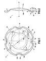
- la
figure 1 est une vue de face de l'implant intraoculaire au repos, c'est-à-dire sans application de contrainte sur la partie haptique ; - la
figure 2 est une vue de côté de l'implant intraoculaire ; et - la
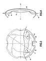
figure 3 est une vue de face partielle montrant la partie haptique de l'implant déformé ; et - la
figure 4 est une vue simplifiée de côté montrant la mise en place de l'implant intraoculaire dans le sac capsulaire. - En se référant tout d'abord aux
figures 1 et 2 , on va décrire les principaux éléments constitutifs de l'implant intraoculaire 10 selon un mode préféré de mise en oeuvre de l'invention. - L'implant intraoculaire 10 est réalisé à partir d'un matériau dit souple typiquement un acrylique hydrophile ou hydrophobe dont un exemple particulier est le produit commercialisé sous la marque Hydrogel. De préférence, l'implant est monobloc.
- L'implant 10 est constitué par une partie optique 12 de forme générale circulaire présentant un bord 12a, un dioptre antérieur 12b et un dioptre postérieur 12c. L'implant intraoculaire comporte également une partie haptique 14 constituée par un anneau circulaire externe 16 constitué par n éléments de contact 18 ayant un bord externe 20 et n éléments de raccordement 22 de forme incurvée interposés entre deux éléments de contact 18 consécutifs. Dans l'exemple considéré, n est égal à 4 ce qui correspond à une solution optimale. Cependant bien entendu n pourrait être différent mais en tout cas au moins égal à 2.
- De préférence, tous les éléments ce contact 18 correspondent à une même longueur d'arc circulaire. Il en va de même pour les éléments de raccordement 22. Grâce à la liaison qui existe entre les extrémités des éléments de contact et les éléments de raccordement, ces deux types d'élément forment une pièce unique, sans interruption, constituant ainsi un anneau sensiblement circulaire fermé.
- L'anneau 16 constituant l'essentiel de la partie haptique est raccordé à la périphérie 12a de la partie optique 12 par n bras 24. Dans l'exemple considéré, il y a quatre bras de raccordement. Chaque élément de contact 18 a la forme d'un arc de cercle au repos centré sur le centre optique O de la partie optique 12 ou plus précisément sur son axe optique X,X'. Les extrémités 18a et 18b de chaque élément de contact 18 sont raccordés aux extrémités 22a ou 22b d'un élément de raccordement 22 adjacent. Chaque bras 24 comporte une première extrémité 24a de raccordement à un élément de contact 18 dans sa partie centrale et une deuxième extrémité 24b de raccordement à la périphérie de la partie optique 12, ces extrémités comportant des congés assurant une certaine rigidification au niveau des deux raccordements.
- Les éléments de contact 18 ont une section droite telle qu'ils soient beaucoup plus rigides que les éléments de raccordement 22 du moins dans un plan parallèle au plan optique de la partie optique 12 de l'implant intraoculaire. Typiquement, l'épaisseur e des bras 24 (selon la direction de l'axe X,X') est très supérieure, au moins égale à deux fois, la largeur l de ces mêmes bras. De la même manière, la largeur l' de chaque élément de raccordement 22 est très inférieure à son épaisseur e'.
- Comme on le voit mieux sur la
figure 2 , les bras 24 présentent une angulation a vers l'avant c'est-à-dire vers le dioptre antérieur 12b par rapport au plan optique PP' de la partie optique 12. En revanche, les éléments de contact 18 présentent une angulation b vers l'arrière par rapport à un plan QQ' parallèle au plan optique PP'. La première angulation a des bras par rapport au plan optique assure le maintien du dioptre postérieur 12c de la partie optique 12 contre la partie postérieure 40 du sac capsulaire 42 comme le montre lafigure 4 . L'angulation b des éléments de contact 18 assure une poussée de la partie optique vers l'avant qui maintient de façon stable la partie optique 12 contre la paroi postérieure 40 du sac capsulaire ainsi que cela a été décrit. - Comme le montre mieux la
figure 2 , les éléments de contact 18 comportent une face antérieure 26, une face postérieure 28 et un rebord 30. Les faces postérieures 28 et le rebord 30 sont déterminés de telle manière qu'ils constituent au moins une arête ou bord carré 32 apte à exercer une pression locale significative sur le sac capsulaire dans la région équatoriale pour former ce qui est appelé le plus souvent un "bord carré" comme on l'a déjà expliqué ce bord carré est apte à bloquer la prolifération de cellules pathogènes de la zone équatoriale du sac capsulaire vers sa paroi postérieure 40. - L'angle entre la face postérieure 28 et le rebord 30 est inférieur à 120 degrés pour constituer l'arête. Dans l'exemple représenté, cet angle est inférieur à 90 degrés en raison de l'angulation b des éléments de contact 18.
- Ainsi qu'on l'a déjà expliqué, les éléments de raccordement 22 ont dans un plan parallèle au plan optique une rigidité très inférieure à celle des éléments de contact 18. Ainsi sous l'effet de la contraction déjà mentionnée du sac capsulaire qui produit donc une diminution du diamètre de celui-ci et grâce au fait que l'ensemble des éléments de contact et des éléments de raccordement forme un anneau fermé, les contraintes résultant de cette contraction appliquées aux bords externes des éléments de contact 18 vont provoquer un fléchissement des éléments de raccordement 22 sans modification de la forme des éléments de contact 18 de telle manière que le diamètre externe D' défini par le bord externe des éléments de contact 18 devienne égal au diamètre réduit du sac capsulaire. Cette déformation localisée dans les zones de raccordement 22 évite d'exercer une poussée vers l'arrière sur la partie optique 12 puisqu'en outre, les bras 24 présentent une flexibilité relativement importante dans des directions sensiblement orthogonales à l'axe optique XX' de la partie optique 12. La déformation des bras 24 suit naturellement la réduction du diamètre externe D' défini par les bords externes des éléments de contact 18.
- Du fait qu'en a, à la fois, réduction du diamètre du cercle sur lequel sont disposés les bords extérieurs 20 des éléments de contact 18, et diminution de la distance entre les extrémités 24a et 24b des bras 24, il n'y a sensiblement pas de déplacement.
- Dans l'exemple particulier décrit, le diamètre externe D de l'implant intraoculaire au repos est égal à 10,5 mm. L'anneau 16 peut se contracter de telle manière qu'on obtienne un diamètre externe de l'haptique contractée D' de l'ordre de 8 mm sans déplacement significatif de la partie optique 12 selon la direction de l'axe optique de l'implant XX'. En outre, compte tenu de la symétrie de révolution de l'anneau 16, les diminutions de diamètre par déformation localisée de cet anneau sont régulières. En conséquence, cette diminution de diamètre n'entraîne aucune prise d'angulation significative de l'axe optique XX' de la partie optique 12 par rapport à l'axe optique naturel de l'oeil XX'.
- D'autres modes de réalisation pourraient être envisagés dès lors que la partie haptique est constituée essentiellement par un anneau au contact de la zone équatoriale du sac capsulaire, cet anneau comportant une alternance de portions en forme d'arc de cercle sensiblement rigide dont les extrémités sont reliées entre elles par des zones de raccordement déformables de telle façon que la réduction de diamètre de l'anneau se fasse de façon localisée dans les éléments de raccordement flexibles.
Claims (8)
- Implant intraoculaire (10) souple destiné à être placé dans un sac capsulaire, comprenant une partie optique (12) de forme sensiblement circulaire et présentant un axe optique (xx') et une partie haptique (14) raccordée à la périphérie de la partie optique, ladite partie haptique (14) comprenant :- une partie de contact (16) constituée par n éléments de contact (n≥ 2) (18) en forme d'arcs de cercle ayant tous le même rayon de courbure et dont le bord externe (20) est destiné à être au contact de la zone équatoriale du sac capsulaire,- n bras de raccordement déformables (24) ayant chacun une première extrémité raccordée à la périphérie (12a) de la partie optique et une deuxième extrémité,- n éléments de raccordement (22), chaque élément de raccordement étant raccordé à une extrémité de deux éléments de contact consécutifs, de manière que les éléments de contact et les éléments de raccordement forment un ensemble annulaire fermé ; les éléments de raccordement ayant une forme incurvée déformable et présentant une rigidité très inférieure à celle des éléments de contact ;
caractérisé en ce que la deuxième extrémité de chaque bras (24) est accordée à l'élément de contact correspondant dans sa partie centrale, par quoi, sous l'effet de la diminution du diamètre du sac capsulaire, les éléments de raccordement et les bras de raccordement se déforment sans entraîner de déplacement significatif de la partie optique selon la direction de son axe optique et sans induire de prise d'angulation significative de l'axe optique de l'implant par rapport à l'axe optique de l'oeil. - Implant intraoculaire selon la revendication 1, caractérisé en ce que les bras de raccordement (24) et les éléments de raccordement (22) présentent une section droite très inférieure à la section droite des éléments de contact (18).
- Implant intraoculaire selon l'une quelconque des revendications 1 et 2, caractérisé en ce que la somme des longueurs des éléments de contact (18) est inférieure au périmètre du sac capsulaire dans son état contracté.
- Implant intraoculaire selon l'une quelconque des revendications 1 à 3, caractérisé en ce que chaque élément de contact (18) comporte un bord (20) sensiblement parallèle à l'axe optique (xx') et deux faces respectivement antérieure (26) et postérieure (28), le bord faisant avec au moins une desdites faces un angle inférieur à 120 degrés formant ainsi une arête ou « bord carré » (30) apte à exercer une pression localisée importante sur ledit sac capsulaire.
- Implant intraoculaire selon l'une quelconque des revendications 1 à 4, caractérisé en ce que, selon la direction de l'axe optique (xx'), au repos, les éléments de contact (18) sont en avant de la partie optique (12).
- Implant intraoculaire selon l'une quelconque des revendications 1 à 5, caractérisé en ce que, en projection dans un plan orthogonal à l'axe optique, chaque bras de raccordement (24) est incliné par rapport à une demi-droite (0,D) portant un rayon de la partie optique.
- Implant intraoculaire selon l'une quelconque des revendications 1 à 6, caractérisé en ce que l'épaisseur (e) de chaque bras de raccordement (24) selon la direction de l'axe optique est supérieure à sa largeur (ℓ) selon une direction orthogonale à l'axe optique.
- Implant intraoculaire selon l'une quelconque des revendications 1 à 7, caractérisé en ce que les éléments de contact (18) présentent une angulation (b) par rapport au plan optique de la partie optique, dirigée vers le dioptre postérieur.
Applications Claiming Priority (2)
| Application Number | Priority Date | Filing Date | Title |
|---|---|---|---|
| FR0756474A FR2918558B1 (fr) | 2007-07-13 | 2007-07-13 | Implant intraoculaire souple a haptique circulaire |
| PCT/FR2008/051301 WO2009013421A1 (fr) | 2007-07-13 | 2008-07-10 | Implant intraoculaire souple a haptique circulaire |
Publications (2)
| Publication Number | Publication Date |
|---|---|
| EP2175806A1 EP2175806A1 (fr) | 2010-04-21 |
| EP2175806B1 true EP2175806B1 (fr) | 2014-09-24 |
Family
ID=38686730
Family Applications (1)
| Application Number | Title | Priority Date | Filing Date |
|---|---|---|---|
| EP08826543.4A Not-in-force EP2175806B1 (fr) | 2007-07-13 | 2008-07-10 | Implant intraoculaire souple a haptique circulaire |
Country Status (7)
| Country | Link |
|---|---|
| US (1) | US8470033B2 (fr) |
| EP (1) | EP2175806B1 (fr) |
| JP (1) | JP2010533019A (fr) |
| CA (1) | CA2696564A1 (fr) |
| ES (1) | ES2526354T3 (fr) |
| FR (1) | FR2918558B1 (fr) |
| WO (1) | WO2009013421A1 (fr) |
Families Citing this family (8)
| Publication number | Priority date | Publication date | Assignee | Title |
|---|---|---|---|---|
| US10010405B2 (en) * | 2008-11-26 | 2018-07-03 | Anew Aol Technologies, Inc. | Haptic devices for intraocular lens |
| AU2009319753B2 (en) * | 2008-11-26 | 2013-11-14 | Anew Iol Technologies, Inc. | Haptic devices for intraocular lens |
| DE102012212722A1 (de) * | 2012-07-19 | 2014-01-23 | Dr. Schmidt Intraocularlinsen Gmbh | Kapselringkörper |
| US10849737B2 (en) * | 2017-07-24 | 2020-12-01 | Alcon Inc. | Intraocular lens having hinged haptic structures |
| US10912642B2 (en) * | 2017-08-18 | 2021-02-09 | Alcon, Inc. | Intraocular lens having an asymmetric hinged closed-loop haptic structure |
| EP3678591A1 (fr) | 2017-11-01 | 2020-07-15 | Alcon Inc. | Lentille intraoculaire ayant des structures haptiques en boucle fermée |
| EP4041130B1 (fr) * | 2019-11-15 | 2026-05-13 | SUTTER, Florian | Lentille intraoculaire ayant un point de courbure cible sur l'haptique |
| CA3198760A1 (en) * | 2023-05-04 | 2025-01-28 | Ocumetics Technology Corp. | Self-adjusting suspension systems for intraocular lenses |
Citations (1)
| Publication number | Priority date | Publication date | Assignee | Title |
|---|---|---|---|---|
| WO2007079315A1 (fr) * | 2005-12-28 | 2007-07-12 | Advanced Medical Optics, Inc. | Lentille intraoculaire d'accommodation dotee d'une structure exterieure de support |
Family Cites Families (6)
| Publication number | Priority date | Publication date | Assignee | Title |
|---|---|---|---|---|
| DE3722910A1 (de) * | 1987-07-10 | 1989-01-19 | Adatomed Pharma & Med | Intraokularlinse |
| JP2599319Y2 (ja) * | 1992-09-30 | 1999-09-06 | ホーヤ・ヘルスケア株式会社 | 眼内レンズ |
| FR2776181B1 (fr) * | 1998-03-20 | 2000-08-11 | Chauvin Opsia | Lentille intraoculaire monobloc souple |
| FR2786686B3 (fr) * | 1998-12-02 | 2001-02-09 | Corneal Ind | Implant intraoculaire en materiau souple |
| FR2800596B1 (fr) * | 1999-11-10 | 2002-03-22 | Ioltechnologie Production | Implant intraoculaire precristallinien |
| FR2841122B1 (fr) * | 2002-06-20 | 2005-04-08 | Corneal Ind | Implant intraoculaire souple, notamment a fixation sclerale |
-
2007
- 2007-07-13 FR FR0756474A patent/FR2918558B1/fr not_active Expired - Fee Related
-
2008
- 2008-07-10 CA CA2696564A patent/CA2696564A1/fr not_active Abandoned
- 2008-07-10 JP JP2010515577A patent/JP2010533019A/ja active Pending
- 2008-07-10 EP EP08826543.4A patent/EP2175806B1/fr not_active Not-in-force
- 2008-07-10 ES ES08826543.4T patent/ES2526354T3/es active Active
- 2008-07-10 US US12/668,842 patent/US8470033B2/en not_active Expired - Fee Related
- 2008-07-10 WO PCT/FR2008/051301 patent/WO2009013421A1/fr not_active Ceased
Patent Citations (1)
| Publication number | Priority date | Publication date | Assignee | Title |
|---|---|---|---|---|
| WO2007079315A1 (fr) * | 2005-12-28 | 2007-07-12 | Advanced Medical Optics, Inc. | Lentille intraoculaire d'accommodation dotee d'une structure exterieure de support |
Also Published As
| Publication number | Publication date |
|---|---|
| CA2696564A1 (fr) | 2009-01-29 |
| EP2175806A1 (fr) | 2010-04-21 |
| US8470033B2 (en) | 2013-06-25 |
| FR2918558B1 (fr) | 2009-10-30 |
| WO2009013421A1 (fr) | 2009-01-29 |
| US20100286772A1 (en) | 2010-11-11 |
| ES2526354T3 (es) | 2015-01-09 |
| FR2918558A1 (fr) | 2009-01-16 |
| JP2010533019A (ja) | 2010-10-21 |
Similar Documents
| Publication | Publication Date | Title |
|---|---|---|
| EP1063946B1 (fr) | Lentille intraoculaire monobloc souple | |
| EP0897294B1 (fr) | Implant intraoculaire monobloc souple | |
| EP2175806A1 (fr) | Implant intraoculaire souple a haptique circulaire | |
| EP1610726B1 (fr) | Lentille intraoculaire et son injecteur | |
| FR2799952A1 (fr) | Implant intraoculaire | |
| EP0698381B1 (fr) | Implant intra-oculaire | |
| EP0886504A1 (fr) | Implant intraoculaire myopique | |
| EP0935448A1 (fr) | Implant intraoculaire a optique souple et a anse unique circulaire rigide | |
| FR2734472A1 (fr) | Lentille intra-oculaire, parties haptique et optique pour une telle lentille et procede de mise en place d'une telle lentille | |
| BE1006003A3 (fr) | Implant intra-oculaire, notamment du type intra-sacculaire. | |
| EP0469993A1 (fr) | Cornée artificielle | |
| FR2922096A1 (fr) | Lentille intraoculaire pour sac capsulaire | |
| EP1732472A2 (fr) | Lentille intra-oculaire perfectionnée | |
| EP2326284B1 (fr) | Lentille intraoculaire | |
| FR2797177A1 (fr) | Implant intraoculaire precristallinien | |
| FR2858544A1 (fr) | Implant intraoculaire souple de faible epaisseur | |
| EP1361836B1 (fr) | Implant intraoculaire en materiau souple | |
| WO1997017915A1 (fr) | Implant intraoculaire souple | |
| EP1176928B1 (fr) | Implant de chambre posterieure aphake chez le myope fort | |
| FR2819713A1 (fr) | Implant intraoculaire monobloc souple | |
| FR2700466A1 (fr) | Implant de chambre postérieure pour aphaque atteint de forte myopie. | |
| FR2766699A1 (fr) | Implant intraoculaire monobloc souple | |
| FR2944427A1 (fr) | Implant intraoculaire | |
| FR2780271A1 (fr) | Implant intraoculaire en materiau souple |
Legal Events
| Date | Code | Title | Description |
|---|---|---|---|
| PUAI | Public reference made under article 153(3) epc to a published international application that has entered the european phase |
Free format text: ORIGINAL CODE: 0009012 |
|
| 17P | Request for examination filed |
Effective date: 20100111 |
|
| AK | Designated contracting states |
Kind code of ref document: A1 Designated state(s): AT BE BG CH CY CZ DE DK EE ES FI FR GB GR HR HU IE IS IT LI LT LU LV MC MT NL NO PL PT RO SE SI SK TR |
|
| AX | Request for extension of the european patent |
Extension state: AL BA MK RS |
|
| 17Q | First examination report despatched |
Effective date: 20100531 |
|
| DAX | Request for extension of the european patent (deleted) | ||
| RAP1 | Party data changed (applicant data changed or rights of an application transferred) |
Owner name: SOURDILLE, PHILIPPE |
|
| RAP1 | Party data changed (applicant data changed or rights of an application transferred) |
Owner name: SOURDILLE, PHILIPPE |
|
| GRAP | Despatch of communication of intention to grant a patent |
Free format text: ORIGINAL CODE: EPIDOSNIGR1 |
|
| INTG | Intention to grant announced |
Effective date: 20140410 |
|
| GRAS | Grant fee paid |
Free format text: ORIGINAL CODE: EPIDOSNIGR3 |
|
| GRAA | (expected) grant |
Free format text: ORIGINAL CODE: 0009210 |
|
| AK | Designated contracting states |
Kind code of ref document: B1 Designated state(s): AT BE BG CH CY CZ DE DK EE ES FI FR GB GR HR HU IE IS IT LI LT LU LV MC MT NL NO PL PT RO SE SI SK TR |
|
| REG | Reference to a national code |
Ref country code: GB Ref legal event code: FG4D Free format text: NOT ENGLISH |
|
| REG | Reference to a national code |
Ref country code: CH Ref legal event code: EP |
|
| REG | Reference to a national code |
Ref country code: AT Ref legal event code: REF Ref document number: 688245 Country of ref document: AT Kind code of ref document: T Effective date: 20141015 |
|
| REG | Reference to a national code |
Ref country code: IE Ref legal event code: FG4D Free format text: LANGUAGE OF EP DOCUMENT: FRENCH |
|
| REG | Reference to a national code |
Ref country code: DE Ref legal event code: R096 Ref document number: 602008034593 Country of ref document: DE Effective date: 20141106 |
|
| REG | Reference to a national code |
Ref country code: ES Ref legal event code: FG2A Ref document number: 2526354 Country of ref document: ES Kind code of ref document: T3 Effective date: 20150109 |
|
| REG | Reference to a national code |
Ref country code: NL Ref legal event code: T3 |
|
| PG25 | Lapsed in a contracting state [announced via postgrant information from national office to epo] |
Ref country code: SE Free format text: LAPSE BECAUSE OF FAILURE TO SUBMIT A TRANSLATION OF THE DESCRIPTION OR TO PAY THE FEE WITHIN THE PRESCRIBED TIME-LIMIT Effective date: 20140924 Ref country code: NO Free format text: LAPSE BECAUSE OF FAILURE TO SUBMIT A TRANSLATION OF THE DESCRIPTION OR TO PAY THE FEE WITHIN THE PRESCRIBED TIME-LIMIT Effective date: 20141224 Ref country code: LT Free format text: LAPSE BECAUSE OF FAILURE TO SUBMIT A TRANSLATION OF THE DESCRIPTION OR TO PAY THE FEE WITHIN THE PRESCRIBED TIME-LIMIT Effective date: 20140924 Ref country code: GR Free format text: LAPSE BECAUSE OF FAILURE TO SUBMIT A TRANSLATION OF THE DESCRIPTION OR TO PAY THE FEE WITHIN THE PRESCRIBED TIME-LIMIT Effective date: 20141225 Ref country code: FI Free format text: LAPSE BECAUSE OF FAILURE TO SUBMIT A TRANSLATION OF THE DESCRIPTION OR TO PAY THE FEE WITHIN THE PRESCRIBED TIME-LIMIT Effective date: 20140924 |
|
| REG | Reference to a national code |
Ref country code: LT Ref legal event code: MG4D |
|
| PG25 | Lapsed in a contracting state [announced via postgrant information from national office to epo] |
Ref country code: CY Free format text: LAPSE BECAUSE OF FAILURE TO SUBMIT A TRANSLATION OF THE DESCRIPTION OR TO PAY THE FEE WITHIN THE PRESCRIBED TIME-LIMIT Effective date: 20140924 Ref country code: LV Free format text: LAPSE BECAUSE OF FAILURE TO SUBMIT A TRANSLATION OF THE DESCRIPTION OR TO PAY THE FEE WITHIN THE PRESCRIBED TIME-LIMIT Effective date: 20140924 Ref country code: HR Free format text: LAPSE BECAUSE OF FAILURE TO SUBMIT A TRANSLATION OF THE DESCRIPTION OR TO PAY THE FEE WITHIN THE PRESCRIBED TIME-LIMIT Effective date: 20140924 |
|
| REG | Reference to a national code |
Ref country code: AT Ref legal event code: MK05 Ref document number: 688245 Country of ref document: AT Kind code of ref document: T Effective date: 20140924 |
|
| PG25 | Lapsed in a contracting state [announced via postgrant information from national office to epo] |
Ref country code: EE Free format text: LAPSE BECAUSE OF FAILURE TO SUBMIT A TRANSLATION OF THE DESCRIPTION OR TO PAY THE FEE WITHIN THE PRESCRIBED TIME-LIMIT Effective date: 20140924 Ref country code: SK Free format text: LAPSE BECAUSE OF FAILURE TO SUBMIT A TRANSLATION OF THE DESCRIPTION OR TO PAY THE FEE WITHIN THE PRESCRIBED TIME-LIMIT Effective date: 20140924 Ref country code: IS Free format text: LAPSE BECAUSE OF FAILURE TO SUBMIT A TRANSLATION OF THE DESCRIPTION OR TO PAY THE FEE WITHIN THE PRESCRIBED TIME-LIMIT Effective date: 20150124 Ref country code: CZ Free format text: LAPSE BECAUSE OF FAILURE TO SUBMIT A TRANSLATION OF THE DESCRIPTION OR TO PAY THE FEE WITHIN THE PRESCRIBED TIME-LIMIT Effective date: 20140924 Ref country code: RO Free format text: LAPSE BECAUSE OF FAILURE TO SUBMIT A TRANSLATION OF THE DESCRIPTION OR TO PAY THE FEE WITHIN THE PRESCRIBED TIME-LIMIT Effective date: 20140924 Ref country code: PT Free format text: LAPSE BECAUSE OF FAILURE TO SUBMIT A TRANSLATION OF THE DESCRIPTION OR TO PAY THE FEE WITHIN THE PRESCRIBED TIME-LIMIT Effective date: 20150126 |
|
| PG25 | Lapsed in a contracting state [announced via postgrant information from national office to epo] |
Ref country code: AT Free format text: LAPSE BECAUSE OF FAILURE TO SUBMIT A TRANSLATION OF THE DESCRIPTION OR TO PAY THE FEE WITHIN THE PRESCRIBED TIME-LIMIT Effective date: 20140924 Ref country code: PL Free format text: LAPSE BECAUSE OF FAILURE TO SUBMIT A TRANSLATION OF THE DESCRIPTION OR TO PAY THE FEE WITHIN THE PRESCRIBED TIME-LIMIT Effective date: 20140924 |
|
| REG | Reference to a national code |
Ref country code: DE Ref legal event code: R097 Ref document number: 602008034593 Country of ref document: DE |
|
| REG | Reference to a national code |
Ref country code: FR Ref legal event code: PLFP Year of fee payment: 8 |
|
| PG25 | Lapsed in a contracting state [announced via postgrant information from national office to epo] |
Ref country code: DK Free format text: LAPSE BECAUSE OF FAILURE TO SUBMIT A TRANSLATION OF THE DESCRIPTION OR TO PAY THE FEE WITHIN THE PRESCRIBED TIME-LIMIT Effective date: 20140924 |
|
| PLBE | No opposition filed within time limit |
Free format text: ORIGINAL CODE: 0009261 |
|
| STAA | Information on the status of an ep patent application or granted ep patent |
Free format text: STATUS: NO OPPOSITION FILED WITHIN TIME LIMIT |
|
| 26N | No opposition filed |
Effective date: 20150625 |
|
| PGFP | Annual fee paid to national office [announced via postgrant information from national office to epo] |
Ref country code: NL Payment date: 20150715 Year of fee payment: 8 |
|
| PGFP | Annual fee paid to national office [announced via postgrant information from national office to epo] |
Ref country code: DE Payment date: 20150713 Year of fee payment: 8 Ref country code: ES Payment date: 20150731 Year of fee payment: 8 Ref country code: GB Payment date: 20150717 Year of fee payment: 8 |
|
| PGFP | Annual fee paid to national office [announced via postgrant information from national office to epo] |
Ref country code: FR Payment date: 20150630 Year of fee payment: 8 Ref country code: BE Payment date: 20150731 Year of fee payment: 8 |
|
| PGFP | Annual fee paid to national office [announced via postgrant information from national office to epo] |
Ref country code: IT Payment date: 20150710 Year of fee payment: 8 |
|
| PG25 | Lapsed in a contracting state [announced via postgrant information from national office to epo] |
Ref country code: MC Free format text: LAPSE BECAUSE OF FAILURE TO SUBMIT A TRANSLATION OF THE DESCRIPTION OR TO PAY THE FEE WITHIN THE PRESCRIBED TIME-LIMIT Effective date: 20140924 Ref country code: SI Free format text: LAPSE BECAUSE OF FAILURE TO SUBMIT A TRANSLATION OF THE DESCRIPTION OR TO PAY THE FEE WITHIN THE PRESCRIBED TIME-LIMIT Effective date: 20140924 |
|
| REG | Reference to a national code |
Ref country code: CH Ref legal event code: PL |
|
| PG25 | Lapsed in a contracting state [announced via postgrant information from national office to epo] |
Ref country code: LU Free format text: LAPSE BECAUSE OF FAILURE TO SUBMIT A TRANSLATION OF THE DESCRIPTION OR TO PAY THE FEE WITHIN THE PRESCRIBED TIME-LIMIT Effective date: 20150710 |
|
| REG | Reference to a national code |
Ref country code: IE Ref legal event code: MM4A |
|
| PG25 | Lapsed in a contracting state [announced via postgrant information from national office to epo] |
Ref country code: CH Free format text: LAPSE BECAUSE OF NON-PAYMENT OF DUE FEES Effective date: 20150731 Ref country code: LI Free format text: LAPSE BECAUSE OF NON-PAYMENT OF DUE FEES Effective date: 20150731 |
|
| PG25 | Lapsed in a contracting state [announced via postgrant information from national office to epo] |
Ref country code: IE Free format text: LAPSE BECAUSE OF NON-PAYMENT OF DUE FEES Effective date: 20150710 |
|
| PG25 | Lapsed in a contracting state [announced via postgrant information from national office to epo] |
Ref country code: BE Free format text: LAPSE BECAUSE OF NON-PAYMENT OF DUE FEES Effective date: 20160731 |
|
| REG | Reference to a national code |
Ref country code: DE Ref legal event code: R119 Ref document number: 602008034593 Country of ref document: DE |
|
| REG | Reference to a national code |
Ref country code: NL Ref legal event code: MM Effective date: 20160801 |
|
| GBPC | Gb: european patent ceased through non-payment of renewal fee |
Effective date: 20160710 |
|
| PG25 | Lapsed in a contracting state [announced via postgrant information from national office to epo] |
Ref country code: MT Free format text: LAPSE BECAUSE OF FAILURE TO SUBMIT A TRANSLATION OF THE DESCRIPTION OR TO PAY THE FEE WITHIN THE PRESCRIBED TIME-LIMIT Effective date: 20140924 |
|
| PG25 | Lapsed in a contracting state [announced via postgrant information from national office to epo] |
Ref country code: DE Free format text: LAPSE BECAUSE OF NON-PAYMENT OF DUE FEES Effective date: 20170201 Ref country code: FR Free format text: LAPSE BECAUSE OF NON-PAYMENT OF DUE FEES Effective date: 20160801 Ref country code: NL Free format text: LAPSE BECAUSE OF NON-PAYMENT OF DUE FEES Effective date: 20160801 |
|
| REG | Reference to a national code |
Ref country code: FR Ref legal event code: ST Effective date: 20170331 |
|
| PG25 | Lapsed in a contracting state [announced via postgrant information from national office to epo] |
Ref country code: BG Free format text: LAPSE BECAUSE OF FAILURE TO SUBMIT A TRANSLATION OF THE DESCRIPTION OR TO PAY THE FEE WITHIN THE PRESCRIBED TIME-LIMIT Effective date: 20140924 Ref country code: GB Free format text: LAPSE BECAUSE OF NON-PAYMENT OF DUE FEES Effective date: 20160710 Ref country code: HU Free format text: LAPSE BECAUSE OF FAILURE TO SUBMIT A TRANSLATION OF THE DESCRIPTION OR TO PAY THE FEE WITHIN THE PRESCRIBED TIME-LIMIT; INVALID AB INITIO Effective date: 20080710 |
|
| PG25 | Lapsed in a contracting state [announced via postgrant information from national office to epo] |
Ref country code: TR Free format text: LAPSE BECAUSE OF FAILURE TO SUBMIT A TRANSLATION OF THE DESCRIPTION OR TO PAY THE FEE WITHIN THE PRESCRIBED TIME-LIMIT Effective date: 20140924 Ref country code: IT Free format text: LAPSE BECAUSE OF NON-PAYMENT OF DUE FEES Effective date: 20160710 |
|
| PG25 | Lapsed in a contracting state [announced via postgrant information from national office to epo] |
Ref country code: ES Free format text: LAPSE BECAUSE OF NON-PAYMENT OF DUE FEES Effective date: 20160711 |
|
| REG | Reference to a national code |
Ref country code: ES Ref legal event code: FD2A Effective date: 20180627 |