EP2176012B1 - Procédé et système pour refouler des éléments creux - Google Patents
Procédé et système pour refouler des éléments creux Download PDFInfo
- Publication number
- EP2176012B1 EP2176012B1 EP08783346.3A EP08783346A EP2176012B1 EP 2176012 B1 EP2176012 B1 EP 2176012B1 EP 08783346 A EP08783346 A EP 08783346A EP 2176012 B1 EP2176012 B1 EP 2176012B1
- Authority
- EP
- European Patent Office
- Prior art keywords
- workpiece
- die
- clamp
- mandrel
- upset
- Prior art date
- Legal status (The legal status is an assumption and is not a legal conclusion. Google has not performed a legal analysis and makes no representation as to the accuracy of the status listed.)
- Not-in-force
Links
Images

Classifications
-
- B—PERFORMING OPERATIONS; TRANSPORTING
- B21—MECHANICAL METAL-WORKING WITHOUT ESSENTIALLY REMOVING MATERIAL; PUNCHING METAL
- B21K—MAKING FORGED OR PRESSED METAL PRODUCTS, e.g. HORSE-SHOES, RIVETS, BOLTS OR WHEELS
- B21K21/00—Making hollow articles not covered by a single preceding sub-group
- B21K21/12—Shaping end portions of hollow articles
-
- B—PERFORMING OPERATIONS; TRANSPORTING
- B21—MECHANICAL METAL-WORKING WITHOUT ESSENTIALLY REMOVING MATERIAL; PUNCHING METAL
- B21J—FORGING; HAMMERING; PRESSING METAL; RIVETING; FORGE FURNACES
- B21J5/00—Methods for forging, hammering, or pressing; Special equipment or accessories therefor
- B21J5/06—Methods for forging, hammering, or pressing; Special equipment or accessories therefor for performing particular operations
- B21J5/08—Upsetting
-
- B—PERFORMING OPERATIONS; TRANSPORTING
- B21—MECHANICAL METAL-WORKING WITHOUT ESSENTIALLY REMOVING MATERIAL; PUNCHING METAL
- B21J—FORGING; HAMMERING; PRESSING METAL; RIVETING; FORGE FURNACES
- B21J9/00—Forging presses
- B21J9/02—Special design or construction
- B21J9/06—Swaging presses; Upsetting presses
Definitions
- the present invention relates to a system and method for upsetting hollow metal members. More specifically, the present invention relates to a system and method for upsetting hollow metal members without requiring the member to be heated for the upsetting operation.
- US 2003/0221474 A1 discloses an apparatus for upsetting a hollow workpiece, on which the preamble of claim 1 is based.
- a method of upsetting a hollow workpiece comprising the steps of loading a workpiece into a clamp, the clamp having a shape complementary to the outer surface of the workpiece; such that an open end of the workpiece that is to be upset extends outside of the clamp; inserting a mandrel into the interior of the workpiece, the mandrel having a complementary shape to the interior cross section of the workpiece and the mandrel extending sufficiently into the workpiece to enter the portion of the workpiece to be held in the clamp; the die being shaped and sized correspondingly to a desired upset size and shape of the end of the workpiece; urging the die toward the clamp to bring the die into contact with the workpiece; driving the die toward the clamp to decrease the length of the end of the workpiece to be upset while increasing the wall thickness of that portion; and once the die has been urged a pre-selected distance toward the clamp, retracting the die and the mandrel from the end of the workpiece to remove the upset workpiece.
- rear axles in front wheel drive passenger vehicles are typically manufactured from a hollow tubular metal member which is formed into the required configuration in a press. While the axle requires a given wall thickness, for example three millimeters, along most of its length, the end portions of the axle can require an increased wall thickness, for example four and a half millimeters, to allow them to be affixed, by welding, to the wheel hub structures.
- feedstock member having the greater wall thickness e.g. four and a half millimeters
- a feedstock member having the smaller wall thickness e.g. three millimeters
- upset, or bulge, the ends of the feedstock member to obtain the necessary larger wall thickness required at the ends of the axle.
- upsetting involves heating the end portions of the hollow member to place the material in a malleable state and then longitudinally compressing the member to deform it, increasing the wall thickness (gauge) of the hollow member in the treated area while decreasing its length.
- hot upsetting provides an advantage in that localized areas of increased gauge can be created, it does suffer from some disadvantages.
- hot upsetting must be performed at a separate manufacturing station where the ends of the hollow member can be heated and compressed and this increases the manufacturing time for the finished part, as well as the increasing the capital costs associated with providing a separate upsetting station and increasing the operating costs associated with operating the heaters for the upsetting operation.
- the heating required for hot upsetting requires a heating and cooling cycle for the upset portions of the hollow member and this heating and cooling cycle alters the properties of the hollow member in the upset areas. This typically necessitates that the upset areas be subsequently treated to harden the upset areas, adding a further process expense.
- a method of upsetting a hollow workpiece according to claim 12.
- an apparatus for upsetting a hollow workpiece according to claim 1.
- the present invention provides an apparatus and method for upsetting a portion of a hollow workpiece to increase the wall thickness of the workpiece.
- a mandrel is inserted into an exposed end of the workpiece and into a clamp, which is then closed to hold the workpiece.
- a die is forced against the exposed end of the workpiece to upset the exposed end by compressing the end towards the clamp, decreasing its length and increasing the wall thickness of the hollow member as required.
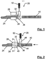
- Apparatus for performing upsetting is indicated generally at 20 in Figure 1 .
- a hollow workpiece 24 is loaded in an upsetting clamp 28 with the end 32 of hollow workpiece 24 which is to be upset being inserted into an upsetting die 36.
- the interior dimensions of die 36 correspond to the desired finished upset size for workpiece 24.
- a mandrel 40 is inserted into the interior of workpiece 24, through dies 36, and extends into workpiece 24 such that at least a portion of mandrel 40 is within clamp 28, as shown in Figure 2 .
- the outer dimensions of mandrel 40 closely correspond to the inner dimensions of workpiece 24.
- Clamp 28 is then closed, as shown in Figure 2 , and tightly engages the outer surface of workpiece 24.
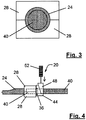
- Clamp 28 and mandrel 40 prevent any deformation of the portion of workpiece 24 held within clamp 28 as shown in Figure 3 .
- workpiece 24 has a circular outer shape and clamp 28 has a corresponding circular shape of its inner clamp surface to receive workpiece 24 and mandrel 40 also has an outer circular shape and size corresponding to the circular shape of the interior of workpiece 24.
- the present invention is not limited to upsetting hollow workpieces 24 with circular outer (or inner) shapes.
- upsetting die 36 is forced towards clamp 28, as shown in Figure 4 , upsetting end 32 by shortening its length while increasing its gauge. Specifically, the length of end 32 is decreased and the material which is displaced by this decrease in length is added to the wall thickness of end 32, increasing its gauge. Mandrel 40 prevents the inner dimensions of end 32 from changing, and the displaced material therefore increases the wall thickness of end 32 until the outer dimensions of end 32 correspond to the inner dimensions of die 36.
- die 36 is mounted to one half cam 44 of a cam-based force multiplier.
- the other half cam 48 of the cam-based force multiplier is connected to a hydraulic ram 52 which, when extended, moves half cam 48 laterally with respect to the length of end 32.
- half cam 48 includes a cam surface which rides on a complementary cam surface on half cam 44, converting the lateral force exerted on half cam 48 by ram 52 into longitudinal force on half cam 44, and die 32, and increasing the longitudinal force applied to die 36, and end 32, from that generated by ram 52.
- the present invention is not limited to the use of force multipliers to move die 36 into contact with end 32 and force can be applied directly to die 36 (or a suitable carrier) in any appropriate manner as will occur to those of skill in the art.
- clamp pressure on clamp 28 is reduced to allow mandrel 40 to be retracted and then clamp 28 is released, as shown in Figure 6 , and upset workpiece 24 can be removed from apparatus 20.
- a method in accordance with the present invention can be considered to comprise the steps of: loading a workpiece into a clamp, the clamp having a shape complementary to the outer surface of the workpiece, and the portion of the workpiece which is to be upset extending outside of the clamp; inserting a mandrel into the interior of the workpiece through a die located adjacent end of the workpiece to be upset, the outer surface of the mandrel having a complementary shape complementary to the interior cross section of the workpiece and the mandrel extending sufficiently into the workpiece to enter the portion of the workpiece to be held in the clamp; closing the clamp; urging the die toward the clamp to bring the die into contact with the workpiece; driving the die toward the clamp to decrease the length of the end of the workpiece to be upset while increasing the wall thickness of that end; and once the die has been force a pre-selected distance towards the clamp, retracting the die and the mandrel from the workpiece and opening the clamp to remove the upset workpiece.
- die 36 and mandrel 40 orientation of die 36 and mandrel 40 relative to end 32 of workpiece 24 allows a concurrent upsetting operation to be performed at the opposite end of workpiece 24.
- another die and another mandrel substantially the mirror images of die 36 and mandrel 40 are positioned at the opposite end of workpiece 24.
- the another die and another mandrel are moveable in the same manner as die 36 and mandrel 40 to upset the opposite end of workpiece 24.
- Die 36 and the other die may be simultaneously driven into contact with workpiece 24 to substantially simultaneously upset both ends of workpiece 24.
- a singular clamp 28 may be used or another clamp may be added to grasp workpiece 24 near the end opposite end 32, depending on the length of workpiece 24.
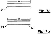
- Figure 7a shows a workpiece 24 prior to upsetting in apparatus 20.
- workpiece 24 has a length of A and includes an end 32 which is to be upset.
- Figure 6b shows the workpiece 24 of Figure 6a after upsetting in apparatus 20.
- the length of workpiece 24 has been reduced by the upsetting from a length of A to a length of B and the wall gauge of workpiece 24 in end 32 has been increased.
- a workpiece comprising a circular tube of 22MNB5 steel which has been subjected to an NBK process (comprising post rolling annealing at approximately 920°C in a controlled atmosphere and controlled heating and cooling cycles) has an end upset.
- the wall thickness of the workpiece is 3.2 mm with the outer diameter of the workpiece being 90 mm.
- the upset portion has a wall thickness of approximately 4.2 mm, and an outer diameter of about 92 mm, and the length of the workpiece is reduced by approximately 15 mm.
- apparatus 20 forms part of a press station for forming workpiece 24 and clamp 28 is closed by the same hydraulic press which is otherwise used to form workpiece 24. Accordingly, clamp 28 is closed with a force in excess of 250 tonnes.
- Ram 52 produces in excess of 50 tonnes of force, which the cam-based force multiplier converts to greater than 150 tonnes of lateral force on die 36 and end 32.
- apparatus 20 can be provided as a separate workstation in a manufacturing process, but as mentioned above, it is contemplated that one of the advantages of the present invention is that apparatus 20 can be included in an existing workstation, such as a forming press. In this manner, cycle times can be reduced, along with the capital expenses which would otherwise be required to establish a separate work station and/or the need for additional plant floor space.
- the method of the present invention does not require heating of workpiece 24 for upsetting, the capital and operating expenses which would be associated with upsetting heaters is avoided and the need for additional hardening or other processing treatments can be avoided.
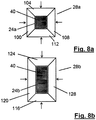
- Figure 8a shows a cross section through a clamp 28a for a workpiece 24a with a square cross section.
- Clamp 28a includes four moveable clamp portions 100, 104, 108 and 112 each of which is urged into contact with a respective side of workpiece 24a when clamp 28a is closed.
- mandrel 40 has a square cross section corresponding to the interior cross section of workpiece 24a.
- Figure 8b shows a clamp 28b for a workpiece 24b with a rectangular cross section.
- Clamp 28b includes four moveable clamp portions 116, 120, 124 and 128 each of which is urged into contact with a respective side of workpiece 24b when clamp 28b is closed.
- mandrel 40 has a square cross section which is complementary to the interior cross section of workpiece 24b.
- die 36 will have a shape and size which corresponds to the desired upset end 32, whether that desired upset end 32 is square, rectangular or any other desired shape.
- die 36 can include one or more desired features, such as a flat or spline, which is formed into the corresponding part of the outer surface of upset portion 30 by dies 36 when the upsetting is performed.
Landscapes
- Engineering & Computer Science (AREA)
- Mechanical Engineering (AREA)
- Forging (AREA)
Claims (19)
- Appareil permettant de refouler une pièce à usiner creuse, comprenant :une pince (28) permettant de saisir la pièce à usiner (24) au niveau d'un emplacement décalé par rapport à une extrémité ouverte de la pièce à usiner (24) qui doit être refoulée, la pince (28) présentant une surface de pincement de forme et de taille complémentaires à la forme externe de la pièce à usiner (24) creuse,un mandrin (40) de taille et de forme complémentaires à la surface intérieure de la pièce à usiner, le mandrin (40) étant mobile dans et hors l'extrémité ouverte de la pièce à usiner (24) qui doit être refoulée, le mandrin (40) pouvant être positionné à l'intérieur de la partie bridée de la pièce à usiner,une matrice (36) comportant une cavité interne de forme et de taille correspondant à la taille et à la forme refoulée souhaitée de l'extrémité de la pièce à usiner (24), etun dispositif d'entraînement pouvant être mis en oeuvre pour déplacer la matrice (36) vers la pince (28) de sorte à ce que la matrice (36) vienne en prise avec l'extrémité de la pièce à usiner (24) à refouler,le dispositif d'entraînement pouvant en outre être mis en oeuvre pour solliciter la matrice (36) avec une distance présélectionnée vers la pince (28) afin de refouler la pièce à usiner (24) y compris la diminution de longueur de l'extrémité de la pièce à usiner (24) tout en augmentant l'épaisseur de paroi de la pièce à usiner (24),caractérisé en ce quela matrice inclut un trou traversant communiquant avec la cavité, le mandrin (40) étant positionnée à l'intérieur du trou traversant pendant le refoulement.
- Appareil selon la revendication 1, dans lequel la cavité de la matrice (36) est définie par une paroi cylindrique coupant une face d'entraînement pratiquement plane, la face d'entraînement pouvant être mise en prise avec une face terminale de la pièce à usiner (24).
- Appareil selon la revendication 2, dans lequel le mandrin (40) peut se déplacer axialement depuis une première position éloignée de la matrice et de la pince (28) jusqu'à une seconde position à l'intérieur de la matrice (36) et de la pince (28), le mandrin (40) entrant d'abord dans la matrice puis entrant dans la pince (28).
- Appareil selon la revendication 3, dans lequel la matrice inclut une face de came en prise grâce à une came entraînée.
- Appareil selon la revendication 4, dans lequel le mouvement axial de la came entraînée dans une première direction provoque le mouvement axial de la matrice (36) dans une seconde direction pratiquement perpendiculaire à la première direction.
- Appareil selon la revendication 2, dans lequel la cavité présente une dimension externe plus grande que la taille de la surface externe de la pièce à usiner (24) avant refoulement afin d'augmenter l'épaisseur de paroi de la pièce à usiner (24) de plus de 30 %.
- Appareil selon la revendication 2, incluant en outre un autre mandrin (40), une autre matrice (36) et un autre dispositif d'entraînement coopérant l'un avec l'autre pour refouler une extrémité ouverte opposée de la pièce à usiner (24).
- Appareil selon la revendication 7, dans lequel le dispositif d'entraînement et l'autre dispositif d'entraînement peuvent être mis en oeuvre pour déplacer la matrice (36) et l'autre matrice (36) l'une vers l'autre pour refouler les extrémités opposées de la pièce à usiner (24).
- Appareil selon la revendication 2, dans lequel la cavité comporte une paroi avec une forme soit circulaire, soit rectangulaire.
- Appareil selon la revendication 2, dans lequel la pince (28) inclut quatre sections déplaçables indépendamment, chacune pouvant être mise en oeuvre pour se mettre en prise avec la surface externe d'une pièce à usiner (24) de forme externe rectangulaire.
- Appareil selon la revendication 2, dans lequel le mandrin (40) présente une forme externe rectangulaire.
- Procédé de refoulement d'une pièce à usiner creuse comprenant les étapes suivantes :le chargement d'une pièce à usiner (24) dans une pince (28), la pince (28) présentant une forme complémentaire à la surface externe de la pièce à usiner (24), de sorte queune extrémité ouverte de la pièce à usiner (24) qui doit être refoulée s'étend vers l'extérieur de la pince (28),l'insertion d'un mandrin (40) à l'intérieur de la pièce à usiner (24) par l'intermédiaire d'une matrice (36) adjacente à l'extrémité de la pièce à usiner (24) et dans l'extrémité ouverte de la pièce à usiner (24), le mandrin (40) présentant une forme complémentaire à la section transversale intérieure de la pièce à usiner (24) et le mandrin (40) se déployant suffisamment dans la pièce à usiner (24) pour entrer dans la partie de la pièce à usiner (24) à maintenir dans la pince (28),la matrice (36) présentant une forme et une taille internes correspondant à une forme et à une taille de refoulement désirées de l'extrémité de la pièce à usiner (24),la fermeture de la pince (28),la sollicitation de la matrice (36) vers la pince (28) afin d'amener la matrice (36) en contact avec la pièce à usiner,l'entraînement de la matrice (36) vers la pince (28) afin de diminuer la longueur de l'extrémité de la pièce à usiner (24) à refouler tout en augmentant l'épaisseur de paroi de cette partie, etune fois que la matrice (36) a été sollicitée d'une distance présélectionnée vers la pince (28), la rétractation de la matrice (36) de l'extrémité, la rétractation du mandrin (40) de la pièce à usiner (24) et l'ouverture de la pince (28) afin de retirer la pièce à usiner (24) refoulée.
- Procédé selon la revendication 12, dans lequel la matrice inclut une cavité définie par une paroi cylindrique coupant une face d'entraînement pratiquement plane, le procédé incluant en outre la mise en prise de la face d'entraînement avec une face terminale de la pièce à usiner (24).
- Procédé selon la revendication 13, incluant en outre le déploiement du mandrin (40) au travers d'un trou formé dans la matrice communiquant avec la cavité.
- Procédé selon la revendication 12, incluant en outre la mise en prise d'une came comportant une face de came formée sur la matrice (36) afin de déplacer la matrice vers la pince (28).
- Procédé selon la revendication 15, incluant en outre une translation axiale de la came dans une première direction afin de déplacer axialement la matrice (36) dans une seconde direction pratiquement perpendiculaire à la première direction.
- Procédé selon la revendication 12, incluant en outre l'augmentation de l'épaisseur de paroi de la pièce à usiner (24) de plus de 30 %.
- Procédé selon la revendication 12, incluant en outre le déplacement de sections indépendantes de la pince (28) l'une par rapport à l'autre pour mettre en prise une surface externe rectangulaire de la pièce à usiner (24).
- Procédé selon la revendication 12, incluant en outre l'entraînement d'une autre matrice (36) vers la pince (28) pour diminuer la longueur de l'extrémité opposée de la pièce à usiner (24) tout en augmentant l'épaisseur de paroi de l'extrémité opposée.
Applications Claiming Priority (2)
| Application Number | Priority Date | Filing Date | Title |
|---|---|---|---|
| US95619807P | 2007-08-16 | 2007-08-16 | |
| PCT/CA2008/001435 WO2009021320A1 (fr) | 2007-08-16 | 2008-08-07 | Procédé et système pour refouler des éléments creux |
Publications (3)
| Publication Number | Publication Date |
|---|---|
| EP2176012A1 EP2176012A1 (fr) | 2010-04-21 |
| EP2176012A4 EP2176012A4 (fr) | 2015-05-20 |
| EP2176012B1 true EP2176012B1 (fr) | 2017-10-11 |
Family
ID=40350314
Family Applications (1)
| Application Number | Title | Priority Date | Filing Date |
|---|---|---|---|
| EP08783346.3A Not-in-force EP2176012B1 (fr) | 2007-08-16 | 2008-08-07 | Procédé et système pour refouler des éléments creux |
Country Status (6)
| Country | Link |
|---|---|
| US (1) | US9457394B2 (fr) |
| EP (1) | EP2176012B1 (fr) |
| BR (1) | BRPI0815411A2 (fr) |
| CA (1) | CA2696169C (fr) |
| MX (1) | MX343003B (fr) |
| WO (1) | WO2009021320A1 (fr) |
Families Citing this family (2)
| Publication number | Priority date | Publication date | Assignee | Title |
|---|---|---|---|---|
| GB2486224B8 (en) * | 2010-12-07 | 2013-06-19 | Europ Technical Ct Etc Steering Nsk Deutschland Gmbh | Tailored thickness steering tube |
| CN102581196B (zh) * | 2012-02-17 | 2017-05-24 | 天津市天锻压力机有限公司 | 翼轨夹紧装置 |
Citations (2)
| Publication number | Priority date | Publication date | Assignee | Title |
|---|---|---|---|---|
| US4362043A (en) * | 1975-09-17 | 1982-12-07 | Hanson Thomas A | Pipe unions |
| US20060260115A1 (en) * | 2005-01-31 | 2006-11-23 | Showa Denko K.K. | Method and apparatus for upsetting cylindrical material |
Family Cites Families (24)
| Publication number | Priority date | Publication date | Assignee | Title |
|---|---|---|---|---|
| US599266A (en) | 1898-02-15 | Device for upsetting metal | ||
| US1837097A (en) | 1930-03-19 | 1931-12-15 | Barth Josef | Process and apparatus for thickening tube ends |
| US1983584A (en) * | 1930-03-29 | 1934-12-11 | Urschel Engineering Company | Process of shaping metal tubes |
| US2078195A (en) | 1934-12-01 | 1937-04-20 | American Radiator Co | Method of manufacturing wrought nonferrous pipe fittings |
| US2319546A (en) | 1940-05-21 | 1943-05-18 | United Aircraft Corp | Method for making valve sleeves |
| US3136053A (en) * | 1960-03-07 | 1964-06-09 | Eastwood Acceptance Corp | Method of forming close tolerance tubing |
| US3224243A (en) | 1961-06-30 | 1965-12-21 | Earl A Thompson Mfg Company | Method of thickening the wall of a tube |
| US3866457A (en) * | 1973-08-24 | 1975-02-18 | Caterpillar Tractor Co | Method and apparatus for tube forming |
| US4048703A (en) | 1975-02-14 | 1977-09-20 | Glyco-Metall-Werke Daelen & Loos Gmbh | Collar sleeves and process and tool for the manufacture thereof |
| US4213322A (en) * | 1978-10-16 | 1980-07-22 | Youngstown Sheet And Tube Company | Method and apparatus for upsetting pipe |
| JPS59215225A (ja) | 1983-05-23 | 1984-12-05 | Ikeda Bussan Co Ltd | パイプ端部のプレス加工装置 |
| DE4104707C2 (de) * | 1991-02-15 | 1994-06-01 | Bruno Jakob Brueck | Vorrichtung zum Anstauchen von flanschartigen Verdickungen an Rohren |
| US5184495A (en) * | 1991-12-03 | 1993-02-09 | Prideco, Inc. | Method of internally and externally upsetting the end of a metal tube |
| US5203194A (en) | 1991-12-05 | 1993-04-20 | Great Lakes Tool And Machine | Method of forming a trailer hitch receiver tube |
| US5283951A (en) | 1992-12-17 | 1994-02-08 | Curtis Products, Inc. | Method of producing a tubing for use as a flow conduit |
| ES2138006T3 (es) * | 1993-04-26 | 2000-01-01 | Bosch Gmbh Robert | Tubo, union de tubos y procedimiento para la fabricacion de tubos para uniones de tubos, asi como dispositivo para la sujecion de tubos. |
| US5517843A (en) * | 1994-03-16 | 1996-05-21 | Shaw Industries, Ltd. | Method for making upset ends on metal pipe and resulting product |
| US6145185A (en) | 1997-10-31 | 2000-11-14 | Hwang; Jeng-Yih | Method for forming a connecting pipe of a high pressure connector for fluid |
| US5884521A (en) * | 1998-07-10 | 1999-03-23 | Lamina, Inc. | High performance aerial and die mount cams |
| CA2483113C (fr) | 1999-02-24 | 2007-10-02 | Copperweld Canada Inc. | Procede d'etirage a froid d'extremite de tubes |
| US6931906B2 (en) * | 2002-03-28 | 2005-08-23 | Eugene Angelo Sorgi | Method and apparatus for cold forging a trailer hitch receiving housing |
| US20050005667A1 (en) * | 2003-07-10 | 2005-01-13 | Greczanik Robert C. | Cold-forged hitch receiver and method of making the same |
| WO2006080503A1 (fr) * | 2005-01-31 | 2006-08-03 | Showa Denko K.K. | Procédé et dispositif de refoulement d’un matériau cylindrique |
| US7647802B2 (en) * | 2006-08-30 | 2010-01-19 | Sunspring America, Inc. | One-piece flexible tube connector and method of making the same |
-
2008
- 2008-08-07 EP EP08783346.3A patent/EP2176012B1/fr not_active Not-in-force
- 2008-08-07 BR BRPI0815411-2A2A patent/BRPI0815411A2/pt not_active IP Right Cessation
- 2008-08-07 US US12/673,032 patent/US9457394B2/en active Active
- 2008-08-07 MX MX2010001819A patent/MX343003B/es active IP Right Grant
- 2008-08-07 CA CA2696169A patent/CA2696169C/fr not_active Expired - Fee Related
- 2008-08-07 WO PCT/CA2008/001435 patent/WO2009021320A1/fr not_active Ceased
Patent Citations (2)
| Publication number | Priority date | Publication date | Assignee | Title |
|---|---|---|---|---|
| US4362043A (en) * | 1975-09-17 | 1982-12-07 | Hanson Thomas A | Pipe unions |
| US20060260115A1 (en) * | 2005-01-31 | 2006-11-23 | Showa Denko K.K. | Method and apparatus for upsetting cylindrical material |
Also Published As
| Publication number | Publication date |
|---|---|
| MX343003B (es) | 2016-10-21 |
| EP2176012A1 (fr) | 2010-04-21 |
| US20110314889A1 (en) | 2011-12-29 |
| US9457394B2 (en) | 2016-10-04 |
| CA2696169C (fr) | 2016-08-23 |
| WO2009021320A1 (fr) | 2009-02-19 |
| MX2010001819A (es) | 2010-03-10 |
| BRPI0815411A2 (pt) | 2015-02-03 |
| CA2696169A1 (fr) | 2009-02-19 |
| EP2176012A4 (fr) | 2015-05-20 |
Similar Documents
| Publication | Publication Date | Title |
|---|---|---|
| US11235367B2 (en) | Method and tool for calibration of a hollow profile component produced by extrusion for automobile manufacturing | |
| EP2285507B1 (fr) | Procédé de fabrication d'un tuyau en acier de grande dimension | |
| EP2517950B1 (fr) | Élément latéral avant de caisse de véhicule automobile | |
| US8776568B2 (en) | Bent member and an apparatus and method for its manufacture | |
| EP2167250B1 (fr) | Dispositif et procédé de façonnage axial de corps creux allongés | |
| EP1112791B1 (fr) | Procédé et appareil pour la fabrication de cremailleres creuses | |
| US7461533B2 (en) | Forging method forged product and forging apparatus | |
| SK285010B6 (sk) | Spôsob výroby podlhovastého hriadeľa s väčším počtom vačiek, najmä vačkového hriadeľa a zariadenie na vykonávanie tohto spôsobu | |
| WO2016198396A1 (fr) | Formage de précision d'extrusions métalliques creuses | |
| EP2759358A1 (fr) | Procédé de fabrication d'une pièce forgée | |
| EP2176012B1 (fr) | Procédé et système pour refouler des éléments creux | |
| US8959973B2 (en) | Method and device for the coreless forming of hollow profiles | |
| US6776020B2 (en) | Method for stretching forming and transporting and aluminum metal sheet | |
| DE102010027093A1 (de) | Verfahren zur Herstellung eines Hohlprofils aus Metall | |
| EP1844875B9 (fr) | Procédé et dispositif de refoulement d'un matériau cylindrique | |
| EP3122490B1 (fr) | Procédé et dispositif de façonnage de tronçons profilés extrudés en magnésium ou alliage de magnésium | |
| US7284403B2 (en) | Apparatus and method for performing a hydroforming process | |
| CA2928490C (fr) | Methode de faconnage d'un tube recepteur d'attache de remorque | |
| DE102009056199A1 (de) | Verfahren zum Umformen eines Halbzeugs |
Legal Events
| Date | Code | Title | Description |
|---|---|---|---|
| PUAI | Public reference made under article 153(3) epc to a published international application that has entered the european phase |
Free format text: ORIGINAL CODE: 0009012 |
|
| 17P | Request for examination filed |
Effective date: 20100201 |
|
| AK | Designated contracting states |
Kind code of ref document: A1 Designated state(s): AT BE BG CH CY CZ DE DK EE ES FI FR GB GR HR HU IE IS IT LI LT LU LV MC MT NL NO PL PT RO SE SI SK TR |
|
| AX | Request for extension of the european patent |
Extension state: AL BA MK RS |
|
| DAX | Request for extension of the european patent (deleted) | ||
| RA4 | Supplementary search report drawn up and despatched (corrected) |
Effective date: 20150420 |
|
| RIC1 | Information provided on ipc code assigned before grant |
Ipc: B21K 21/12 20060101ALI20150414BHEP Ipc: B21J 5/08 20060101AFI20150414BHEP Ipc: B21D 51/00 20060101ALI20150414BHEP Ipc: B21J 9/06 20060101ALI20150414BHEP |
|
| 17Q | First examination report despatched |
Effective date: 20160517 |
|
| GRAP | Despatch of communication of intention to grant a patent |
Free format text: ORIGINAL CODE: EPIDOSNIGR1 |
|
| INTG | Intention to grant announced |
Effective date: 20170511 |
|
| GRAS | Grant fee paid |
Free format text: ORIGINAL CODE: EPIDOSNIGR3 |
|
| GRAA | (expected) grant |
Free format text: ORIGINAL CODE: 0009210 |
|
| AK | Designated contracting states |
Kind code of ref document: B1 Designated state(s): AT BE BG CH CY CZ DE DK EE ES FI FR GB GR HR HU IE IS IT LI LT LU LV MC MT NL NO PL PT RO SE SI SK TR |
|
| REG | Reference to a national code |
Ref country code: GB Ref legal event code: FG4D |
|
| REG | Reference to a national code |
Ref country code: CH Ref legal event code: EP |
|
| REG | Reference to a national code |
Ref country code: IE Ref legal event code: FG4D |
|
| REG | Reference to a national code |
Ref country code: AT Ref legal event code: REF Ref document number: 935575 Country of ref document: AT Kind code of ref document: T Effective date: 20171115 |
|
| REG | Reference to a national code |
Ref country code: DE Ref legal event code: R096 Ref document number: 602008052470 Country of ref document: DE |
|
| REG | Reference to a national code |
Ref country code: NL Ref legal event code: MP Effective date: 20171011 |
|
| REG | Reference to a national code |
Ref country code: LT Ref legal event code: MG4D |
|
| REG | Reference to a national code |
Ref country code: AT Ref legal event code: MK05 Ref document number: 935575 Country of ref document: AT Kind code of ref document: T Effective date: 20171011 |
|
| PG25 | Lapsed in a contracting state [announced via postgrant information from national office to epo] |
Ref country code: NL Free format text: LAPSE BECAUSE OF FAILURE TO SUBMIT A TRANSLATION OF THE DESCRIPTION OR TO PAY THE FEE WITHIN THE PRESCRIBED TIME-LIMIT Effective date: 20171011 |
|
| PG25 | Lapsed in a contracting state [announced via postgrant information from national office to epo] |
Ref country code: SE Free format text: LAPSE BECAUSE OF FAILURE TO SUBMIT A TRANSLATION OF THE DESCRIPTION OR TO PAY THE FEE WITHIN THE PRESCRIBED TIME-LIMIT Effective date: 20171011 Ref country code: LT Free format text: LAPSE BECAUSE OF FAILURE TO SUBMIT A TRANSLATION OF THE DESCRIPTION OR TO PAY THE FEE WITHIN THE PRESCRIBED TIME-LIMIT Effective date: 20171011 Ref country code: NO Free format text: LAPSE BECAUSE OF FAILURE TO SUBMIT A TRANSLATION OF THE DESCRIPTION OR TO PAY THE FEE WITHIN THE PRESCRIBED TIME-LIMIT Effective date: 20180111 Ref country code: ES Free format text: LAPSE BECAUSE OF FAILURE TO SUBMIT A TRANSLATION OF THE DESCRIPTION OR TO PAY THE FEE WITHIN THE PRESCRIBED TIME-LIMIT Effective date: 20171011 Ref country code: FI Free format text: LAPSE BECAUSE OF FAILURE TO SUBMIT A TRANSLATION OF THE DESCRIPTION OR TO PAY THE FEE WITHIN THE PRESCRIBED TIME-LIMIT Effective date: 20171011 |
|
| PG25 | Lapsed in a contracting state [announced via postgrant information from national office to epo] |
Ref country code: IS Free format text: LAPSE BECAUSE OF FAILURE TO SUBMIT A TRANSLATION OF THE DESCRIPTION OR TO PAY THE FEE WITHIN THE PRESCRIBED TIME-LIMIT Effective date: 20180211 Ref country code: HR Free format text: LAPSE BECAUSE OF FAILURE TO SUBMIT A TRANSLATION OF THE DESCRIPTION OR TO PAY THE FEE WITHIN THE PRESCRIBED TIME-LIMIT Effective date: 20171011 Ref country code: AT Free format text: LAPSE BECAUSE OF FAILURE TO SUBMIT A TRANSLATION OF THE DESCRIPTION OR TO PAY THE FEE WITHIN THE PRESCRIBED TIME-LIMIT Effective date: 20171011 Ref country code: BG Free format text: LAPSE BECAUSE OF FAILURE TO SUBMIT A TRANSLATION OF THE DESCRIPTION OR TO PAY THE FEE WITHIN THE PRESCRIBED TIME-LIMIT Effective date: 20180111 Ref country code: LV Free format text: LAPSE BECAUSE OF FAILURE TO SUBMIT A TRANSLATION OF THE DESCRIPTION OR TO PAY THE FEE WITHIN THE PRESCRIBED TIME-LIMIT Effective date: 20171011 Ref country code: GR Free format text: LAPSE BECAUSE OF FAILURE TO SUBMIT A TRANSLATION OF THE DESCRIPTION OR TO PAY THE FEE WITHIN THE PRESCRIBED TIME-LIMIT Effective date: 20180112 |
|
| REG | Reference to a national code |
Ref country code: DE Ref legal event code: R097 Ref document number: 602008052470 Country of ref document: DE |
|
| PG25 | Lapsed in a contracting state [announced via postgrant information from national office to epo] |
Ref country code: CZ Free format text: LAPSE BECAUSE OF FAILURE TO SUBMIT A TRANSLATION OF THE DESCRIPTION OR TO PAY THE FEE WITHIN THE PRESCRIBED TIME-LIMIT Effective date: 20171011 Ref country code: DK Free format text: LAPSE BECAUSE OF FAILURE TO SUBMIT A TRANSLATION OF THE DESCRIPTION OR TO PAY THE FEE WITHIN THE PRESCRIBED TIME-LIMIT Effective date: 20171011 Ref country code: EE Free format text: LAPSE BECAUSE OF FAILURE TO SUBMIT A TRANSLATION OF THE DESCRIPTION OR TO PAY THE FEE WITHIN THE PRESCRIBED TIME-LIMIT Effective date: 20171011 Ref country code: SK Free format text: LAPSE BECAUSE OF FAILURE TO SUBMIT A TRANSLATION OF THE DESCRIPTION OR TO PAY THE FEE WITHIN THE PRESCRIBED TIME-LIMIT Effective date: 20171011 |
|
| PLBE | No opposition filed within time limit |
Free format text: ORIGINAL CODE: 0009261 |
|
| STAA | Information on the status of an ep patent application or granted ep patent |
Free format text: STATUS: NO OPPOSITION FILED WITHIN TIME LIMIT |
|
| PG25 | Lapsed in a contracting state [announced via postgrant information from national office to epo] |
Ref country code: IT Free format text: LAPSE BECAUSE OF FAILURE TO SUBMIT A TRANSLATION OF THE DESCRIPTION OR TO PAY THE FEE WITHIN THE PRESCRIBED TIME-LIMIT Effective date: 20171011 Ref country code: RO Free format text: LAPSE BECAUSE OF FAILURE TO SUBMIT A TRANSLATION OF THE DESCRIPTION OR TO PAY THE FEE WITHIN THE PRESCRIBED TIME-LIMIT Effective date: 20171011 Ref country code: PL Free format text: LAPSE BECAUSE OF FAILURE TO SUBMIT A TRANSLATION OF THE DESCRIPTION OR TO PAY THE FEE WITHIN THE PRESCRIBED TIME-LIMIT Effective date: 20171011 |
|
| 26N | No opposition filed |
Effective date: 20180712 |
|
| PG25 | Lapsed in a contracting state [announced via postgrant information from national office to epo] |
Ref country code: SI Free format text: LAPSE BECAUSE OF FAILURE TO SUBMIT A TRANSLATION OF THE DESCRIPTION OR TO PAY THE FEE WITHIN THE PRESCRIBED TIME-LIMIT Effective date: 20171011 |
|
| PG25 | Lapsed in a contracting state [announced via postgrant information from national office to epo] |
Ref country code: MC Free format text: LAPSE BECAUSE OF FAILURE TO SUBMIT A TRANSLATION OF THE DESCRIPTION OR TO PAY THE FEE WITHIN THE PRESCRIBED TIME-LIMIT Effective date: 20171011 |
|
| REG | Reference to a national code |
Ref country code: CH Ref legal event code: PL |
|
| GBPC | Gb: european patent ceased through non-payment of renewal fee |
Effective date: 20180807 |
|
| PG25 | Lapsed in a contracting state [announced via postgrant information from national office to epo] |
Ref country code: CH Free format text: LAPSE BECAUSE OF NON-PAYMENT OF DUE FEES Effective date: 20180831 Ref country code: LI Free format text: LAPSE BECAUSE OF NON-PAYMENT OF DUE FEES Effective date: 20180831 Ref country code: LU Free format text: LAPSE BECAUSE OF NON-PAYMENT OF DUE FEES Effective date: 20180807 |
|
| REG | Reference to a national code |
Ref country code: BE Ref legal event code: MM Effective date: 20180831 |
|
| REG | Reference to a national code |
Ref country code: IE Ref legal event code: MM4A |
|
| PG25 | Lapsed in a contracting state [announced via postgrant information from national office to epo] |
Ref country code: IE Free format text: LAPSE BECAUSE OF NON-PAYMENT OF DUE FEES Effective date: 20180807 |
|
| PG25 | Lapsed in a contracting state [announced via postgrant information from national office to epo] |
Ref country code: BE Free format text: LAPSE BECAUSE OF NON-PAYMENT OF DUE FEES Effective date: 20180831 Ref country code: FR Free format text: LAPSE BECAUSE OF NON-PAYMENT OF DUE FEES Effective date: 20180831 |
|
| PG25 | Lapsed in a contracting state [announced via postgrant information from national office to epo] |
Ref country code: GB Free format text: LAPSE BECAUSE OF NON-PAYMENT OF DUE FEES Effective date: 20180807 |
|
| PG25 | Lapsed in a contracting state [announced via postgrant information from national office to epo] |
Ref country code: MT Free format text: LAPSE BECAUSE OF NON-PAYMENT OF DUE FEES Effective date: 20180807 |
|
| PG25 | Lapsed in a contracting state [announced via postgrant information from national office to epo] |
Ref country code: TR Free format text: LAPSE BECAUSE OF FAILURE TO SUBMIT A TRANSLATION OF THE DESCRIPTION OR TO PAY THE FEE WITHIN THE PRESCRIBED TIME-LIMIT Effective date: 20171011 |
|
| PG25 | Lapsed in a contracting state [announced via postgrant information from national office to epo] |
Ref country code: PT Free format text: LAPSE BECAUSE OF FAILURE TO SUBMIT A TRANSLATION OF THE DESCRIPTION OR TO PAY THE FEE WITHIN THE PRESCRIBED TIME-LIMIT Effective date: 20171011 Ref country code: HU Free format text: LAPSE BECAUSE OF FAILURE TO SUBMIT A TRANSLATION OF THE DESCRIPTION OR TO PAY THE FEE WITHIN THE PRESCRIBED TIME-LIMIT; INVALID AB INITIO Effective date: 20080807 |
|
| PG25 | Lapsed in a contracting state [announced via postgrant information from national office to epo] |
Ref country code: CY Free format text: LAPSE BECAUSE OF FAILURE TO SUBMIT A TRANSLATION OF THE DESCRIPTION OR TO PAY THE FEE WITHIN THE PRESCRIBED TIME-LIMIT Effective date: 20171011 |
|
| PGFP | Annual fee paid to national office [announced via postgrant information from national office to epo] |
Ref country code: DE Payment date: 20240612 Year of fee payment: 17 |
|
| REG | Reference to a national code |
Ref country code: DE Ref legal event code: R119 Ref document number: 602008052470 Country of ref document: DE |