EP2176042B1 - Rasierapparat - Google Patents
Rasierapparat Download PDFInfo
- Publication number
- EP2176042B1 EP2176042B1 EP08745431A EP08745431A EP2176042B1 EP 2176042 B1 EP2176042 B1 EP 2176042B1 EP 08745431 A EP08745431 A EP 08745431A EP 08745431 A EP08745431 A EP 08745431A EP 2176042 B1 EP2176042 B1 EP 2176042B1
- Authority
- EP
- European Patent Office
- Prior art keywords
- aid body
- shaving aid
- shaving
- handle
- carriage
- Prior art date
- Legal status (The legal status is an assumption and is not a legal conclusion. Google has not performed a legal analysis and makes no representation as to the accuracy of the status listed.)
- Active
Links
Images



Classifications
-
- B—PERFORMING OPERATIONS; TRANSPORTING
- B26—HAND CUTTING TOOLS; CUTTING; SEVERING
- B26B—HAND-HELD CUTTING TOOLS NOT OTHERWISE PROVIDED FOR
- B26B21/00—Razors of the open or knife type; Safety razors or other shaving implements of the planing type; Hair-trimming devices involving a razor-blade; Equipment therefor
- B26B21/40—Details or accessories
- B26B21/44—Means integral with, or attached to, the razor for storing shaving-cream, styptic, or the like
Definitions
- the present invention is related to shaving implements in general and, more particularly, to shaving implements having improved abilities to maintain contact with surfaces being shaved.
- Shaving implements typically include a razor cartridge mounted to a handle.
- the cartridge includes a housing having at least one razor blade having a cutting edge, that is located aft of a leading portion of the housing and forward of a trailing portion of the housing.
- a guard is mounted to or integral with the leading portion and a cap is mounted to or integral with the trailing portion.
- the guard and cap each have skin-engaging surfaces that cooperate to define a theoretical shave plane tangential to each of the guard and cap skin-engaging surfaces.
- the at least one razor blade is disposed such that its cutting edge is adjacent the shave plane.
- the razor cartridge may be movably mounted to the handle to allow the razor blades an increased range of movement during a shaving operation. Shaving aid material is often applied in anticipation of, or during a shaving operation to soften the hairs, condition the skin, provide lubrication, etc.
- a shaving aid body comprising a soap-type shaving aid material may be positioned to partially or entirely surround the razor cartridge, thereby enabling a user to apply shaving aid material during the shaving process.
- soap-type shaving aid materials erode during use, most of these types of shaving implements include a self-leveling mechanism that keeps the top surface of the shaving aid body and the shave plane of the razor cartridge substantially coplanar during use in order to provide the device with a suitable service life (see e.g. US-A-2003/0200660 and US-A-2005/0172495 ).
- the shaving aid body and the razor cartridge move relative to each other in order for the shaving aid body and the razor cartridge to remain coplanar during the shaving operation. By remaining coplanar, both the shaving aid body and the razor blades contact the skin simultaneously during normal shaving.
- pivotal motion of the razor cartridge relative to the shaving aid body is also permitted (see e.g. US-A-2007/0006464 ).
- the nature of limited pivotal movement or non-pivotal movement of the razor cartridge may cause the razor blades to occasionally lose contact with the surface being shaved, particularly as the user moves the implement over a relatively sharply-defined contour in the surface (e.g., over the edge defined by the ankle or shin, or over a fold of skin in the axillary region).
- a less-than-optimum shave may be produced, which may result in the user having to shave one area several times.
- the razor blades By causing the razor blades to engage and re-engage the same surface multiple times, the skin, particularly in sensitive areas, may become irritated and cause discomfort to the person being shaved.
- a shaving implement that is capable of maintaining the razor blades and the shaving aid body in contact with the surface being shaved over difficult-to-shave contours.
- a first pivoting arrangement is disposed between the handle and the shaving aid body that permits limited pivotal motion of razor cartridge and shaving aid body, together as a unit about an axis generally parallel to an elongated cutting edge of the razor cartridge.
- a second pivoting arrangement is disposed in the self-leveling mechanism and is attached between a platform of a carriage attached to the shaving aid body and the handle. The second pivoting arrangement permits pivotal movement of the razor cartridge and the shaving aid body, together, relative to the handle about at least one of a second axis and a third axis.
- the second axis extends generally parallel to the direction of self-leveling movement of at least one of the razor cartridge and the shaving aid body and generally perpendicular to the first axis.
- the third axis extends generally perpendicular to both the first and second axes. Biasing force can be provided to provide the replacement cartridge with a neutral position in relation to all three axes relative to the handle.
- the handle includes a handle housing and a self-leveling mechanism disposed partially within the housing.
- the self-leveling mechanism includes a razor cartridge carriage and a shaving aid body carriage.
- the self-leveling mechanism permits generally linear motion of one of the razor cartridge carriage and shaving aid body carriage in a first direction.
- the other of the razor cartridge carriage and shaving aid body carriage can move in a generally opposite direction.
- the shaving aid body carriage includes a slider having a concave partially spherical surface and a platform having a convex partially spherical surface.
- the concave and convex partially spherical surfaces of the slider and platform mate to provide a ball joint, also known as a ball and socket joint, that permits pivotal movement of the shaving aid body carriage relative to the housing about an axis generally parallel to the direction of self-leveling movement of one of the razor cartridge carriage and the shaving aid body carriage.
- a ball joint also known as a ball and socket joint
- the permitted pivotal motions of the replacement cartridge relative to its handle allows the razor blades more likely to remain in contact with the surface being shaved, as compared to shaving implements in which one or both of the razor cartridge and shaving aid body do not pivot relative to the handle or pivot about only one axis.
- the shaving implement 10 includes a handle 12, a shaving aid body 14 operably attached to the handle, and a razor cartridge 16 operably connected to the handle.
- the shaving aid body 14 and the razor cartridge 16 together comprise a replacement cartridge 20 and the replacement cartridge is mounted on the handle 12 such that both the shaving aid body and the razor cartridge are pivotal as a unit relative to the handle in a manner that will be described later in the present application.
- the handle includes a handle housing 11 having a self-leveling mechanism 60 that will also be described later in the present application that enables the shaving aid body 14 to move relative to the razor cartridge 16.
- the handle 12 is of any suitable shape and size that allows it to be gripped and manipulated by the user.
- One exemplary type of handle is shown and described in U.S.-D-500,169 .
- the present invention is not limited in this regard, and other handles are within the scope of the present invention.
- the handle 12 is preferably ergonomically or similarly contoured.
- the replacement cartridge includes a razor cartridge 16.
- the razor cartridge includes a cartridge housing 30 including at least one razor blade 32 having an elongated cutting edge 34 disposed therein. In the razor cartridge depicted, three razor blades are shown, but the present invention is not limited in this regard and more or less than three razor blades can be usefully employed.
- the cartridge housing has a cap 36 positioned aft of the razor blade(s) and a guard 38 positioned forward of the razor blade(s). The skin engaging surfaces of both the guard and cap cooperate to define a theoretical plane (not shown) known as the shave plane, tangent to both.
- the cutting edge(s) of the razor blade(s) are arranged adjacent to the shave plane.
- the razor cartridge is pivotally attached to a holder 40 which is in turn slidably coupled to a base 44 of the shaving aid body.
- the execution of this attachment and slidable coupling between the razor cartridge, the holder and the base are well known to one of skill in the art and are described for example in U.S.-A-2003/0200660 .
- the shaving aid body 14 includes a body of a shaving aid material 42 attached to a base 44.
- a body of a shaving aid material 42 attached to a base 44.
- One exemplary type of shaving aid body is disclosed in U.S.-B-7,370,419 .
- the shaving aid body 14 can include any suitable type of shaving aid material, such as an erodable solid body of shaving aid material that is selected to suit the application at hand.
- a soap-type shaving aid material is particularly well-suited for wet shaving applications in which the shaving implement 10 may be used.
- Other shaving aid materials e.g., lubricating agents, drag-reducing agents, depilatory agents, cleaning agents, medicinal agents, sensory agents, skin stimulators, etc.
- the present invention is not limited to erodable soap-type shaving aid materials, however, and other types of material such as non-erodable foams or similar porous material from which soaps or other shaving aid materials may be exuded are within the scope of the present invention.
- the top, skin contacting surface 18 continually changes during normal use.
- a self-leveling mechanism is provided to allow the razor cartridge 16 to move relative to the shaving aid body 14.
- the shaving aid body 14 is arranged such that at least a portion of the shaving aid material is adjacent the razor cartridge 16.
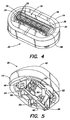
- the shaving aid body shown particularly in Fig. 4 is a single oval having a center aperture 19 in which the razor cartridge is disposed.
- the shaving aid body can comprise one or more sections adjacent the razor cartridge, e.g.: a forward portion or portions; an aft portion or portions and/or side portions.
- the base 44 includes apertured tabs 46 or the like that enable the shaving aid body and the razor cartridge to pivot relative to the handle about a first axis 48 (represented diagramatically in Fig. 1 ) through a limited range of motion represented diagramatically as 49 in Fig. 2 .
- the base includes a first axis biasing member, preferably leaf springs 52 that provide a restoring moment to return the replacement cartridge to the neutral position of its first axis pivotal motion. Exemplary executions of the provision of pivotal motion about the first axis are disclosed in U.S.-A-2007/0006464 .
- Mounting pins 50 extend from the base 44 to facilitate the location of the base in the handle.
- the base 44 can be made of any suitable material known to those of skill in the art; however, plastics such as polypropylene and ABS have proven to have particular utility.
- the self-leveling mechanism assembly comprises a shaving aid body carriage 62, a razor cartridge carriage, 64 and a pivot link 66 having a pivot link axis 67.
- the relative motions of the aforementioned parts in conjunction with the handle housing to provide a self-leveling function are well known and are disclosed for example in the aforementioned U.S.-A-2003/0200660 .
- the shaving aid body carriage 62 comprises a slider 70 and a platform 80.
- the self-leveling mechanism assembly also comprises second and third axes biasing members that include springs 68 that are preferably tension springs or elastomeric bands.
- the springs extend between protrusions 72 and 82 respectively of the slider and platform.
- the springs are preferably arranged in a cross pattern as depicted and are disposed at each end of the mechanism assembly.
- the springs may also be arranged side-by-side.
- the springs provide a restoring moment to return the platform, and thus a replacement cartridge that may be mounted to the platform, to a neutral position relative to second and third axis pivotal motions as will be described later in the present application.
- the springs preferably have similar spring constants such that the restoring moment about one of the second and third axes is similar to the restoring moment about the other of the second and third axes.
- the springs may also be arranged such that the restoring moment about the second axis is less than or greater than the restoring moment about the third axis.
- the platform 80 of the shaving aid body carriage is depicted.
- the platform includes slots 84 to accept the mounting pins 50 of the base of the replacement cartridge when a replacement cartridge is attached to the handle.
- the platform includes a protrusion 86 to engage the aperture of the tab 46 of the base of the replacement cartridge when a replacement cartridge is attached to the handle that together provide pivotal motion about the first axis.
- the platform further includes a convex partially spherical surface 88 and a fulcrum 90, the function of both will be described later in the present application.
- the slider 70 of the shaving aid body carriage is depicted.
- the slider includes mounting protrusions 72 for the second and third axes biasing members.
- the slider includes a concave partially spherical surface 74 and a pad 76.
- the concave and convex partially spherical surfaces mate to form a ball joint, also known as a ball and socket joint.
- Fulcrum 90 abuts pad 76.
- a theoretical ball joint provides limited universal motion, ie limited pivotal motion about three mutually perpendicular axes, of its ball relative to its socket, abutment of the fulcrum 90 and pad 76 limit the motion of the platform relative to the slider to pivotal motion about two axes and combinations thereof.
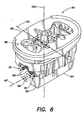
- the two axes are represented diagrammatically in Figs 1- 3 and 6 and are defined as the second axis 100 and the third axis 110.
- Permitted pivotal motion of the replacement cartridge about each axis through a limited range of motion is represented diagrammatically as 101 and 111 respectively in Figs 1 and 3 .
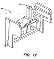
- the razor cartridge carriage 64 of the self-leveling mechanism 60 is depicted.
- the razor cartridge carriage includes a post 92 that connects to the holder 40 of the replacement cartridge, by abutting the holder, when a replacement cartridge is attached to the handle.
- the replacement cartridge when a replacement cartridge is connected to the handle described herein to provide a shaving implement, the replacement cartridge is provided with limited pivotal motion about at least two and preferably three axes, and combinations thereof, against biasing forces that provide a neutral position relative to all axes.
- the three axes are: a first axis generally parallel to the elongated cutting edge of the razor blade of the razor cartridge; a second axis, generally perpendicular to the first axis and generally parallel to the direction of self-leveling motion of one or both the razor cartridge and shaving aid body; and a third axis generally perpendicular to both the first and second axes.
- the permitted pivotal motions of the replacement cartridge relative to its handle allows the razor blades more likely to remain in contact with the surface being shaved, as compared to shaving implements in which one or both of the razor cartridge and shaving aid body do not pivot relative to the handle or pivot about only one axis.
Landscapes
- Life Sciences & Earth Sciences (AREA)
- Forests & Forestry (AREA)
- Engineering & Computer Science (AREA)
- Mechanical Engineering (AREA)
- Cosmetics (AREA)
- Pens And Brushes (AREA)
- Semiconductor Lasers (AREA)
- Crystals, And After-Treatments Of Crystals (AREA)
- Led Devices (AREA)
Claims (9)
- Rasierapparat mit:- einem Griff (12) mit einer Rasierhilfsmittelkörper-Trägerplattform (80),- einer eine Rasierebene definierende Rasierer-Cartridge (16),- einem mit dem Griff (12) verbundenen Rasierhilfsmittelkörper (14), wobei der Rasierhilfsmittelkörper (14) eine Oberseite aufweist, und wobei mindestens ein Bereich des Rasierhilfsmittelkörpers (14) der Rasierer-Cartridge (16) benachbart ist,- einer ersten Schwenkeinrichtung, die an dem Rasierhilfsmittelkörper (14) und dem Griff (12) angebracht ist, wobei die erste Schwenkeinrichtung eine gemeinsame Schwenkbewegung der Rasierer-Cartridge (16) und des Rasierhilfsmittelkörpers (14) um eine erste Achse (48) in Bezug auf den Griff ermöglicht, und- einer Selbstnivellierungseinrichtung (60), die an der Rasierer-Cartridge (16) und dem Rasierhilfsmittelkörper (14) angebracht ist, wobei die Selbstnivellierungseinrichtung (60) das Bewegen der Rasierer-Cartridge (16) und/oder des Rasierhilfsmittelkörpers (14) ermöglicht, um zu erreichen, dass die Oberseite des Rasierhilfsmittelkörpers (14) während eines Rasiervorgangs komplanar mit der Rasierebene bleibt,
gekennzeichnet durch- eine zweite Schwenkeinrichtung, die an der Rasierhilfsmittelkörper-Trägerplattform (80) und dem Griff (12) angebracht ist, wobei die zweite Schwenkeinrichtung eine gemeinsame Schwenkbewegung der Rasierer-Cartridge (16) und des Rasierhilfsmittelkörpers (14) um eine zweite (100) und/oder dritte Achse (110) in Bezug auf den Griff (12) ermöglicht, wobei die zweite Achse (100) sich im Wesentlichen parallel zur Bewegungsrichtung der Rasierer-Cartridge (16) und/oder des Rasierhilfsmittelkörpers (14) erstreckt, und wobei die dritte Achse (110) sich im wesentlichen senkrecht zu sowohl der ersten Achse als auch der zweiten Achse (48, 100) erstreckt. - Rasierapparat nach Anspruch 1, bei welchem der Griff (12) ferner einen Rasierhilfsmittelkörper-Trägerschieber (70) aufweist, und wobei der Rasierhilfsmittelkörper-Trägerschieber (70) und die Rasierhilfsmittelkörper-Trägerplattform (80) zur Bildung eines Kugelgelenks zusammenwirken.
- Rasierapparat nach Anspruch 1 oder 2, ferner mit einem Vorspannelement (68), das arbeitet, um den Rasierhilfsmittelkörper (14) und die Rasierer-Cartridge (16) zusammen in Bezug auf mindestens eine der zweiten und der dritten Achse (100, 110) in Richtung einer neutralen Position relativ zu dem Griff zu drücken.
- Rasierapparat nach Anspruch 3, bei welchem das Vorspannelement (68) eine Feder ist.
- Rasierapparat nach einem der Ansprüche 1 bis 4, bei welchem der Rasierhilfsmittelkörper (14) ein erodierbarer Festkörper ist.
- Griff für einen Rasierapparat, mit:- einem Griffgehäuse (11), und- einer Selbstnivellierungseinrichtung (60), die teilweise in dem Gehäuse (11) angeordnet ist, wobei die Selbstnivellierungseinrichtung (60) einen Rasierer-Cartridge-Träger (64) und einen Rasierhilfsmittelkörperträger (62) aufweist,- wobei das Bewegen eines Elements, nämlich des Rasierer-Cartridge-Trägers (64) oder des Rasierhilfsmittelkörperträgers (62), in eine erste Richtung, bewirkt, dass sich das andere Element, nämlich der Rasierer-Cartridge-Träger (64) oder der Rasierhilfsmittelkörperträger (62) in eine zu der ersten Richtung im Wesentlichen entgegengesetzte Richtung bewegt,
dadurch gekennzeichnet, dass- der Rasierhilfsmittelkörperträger (62) aufweist:- einen Schieber (70) mit einer konkaven, teilweise sphärischen Fläche (74), und- eine Plattform (80) mit einer konvexen, teilweise sphärischen Fläche (88),- wobei die konkave sphärische Fläche (74) und die konvexe sphärische Fläche (88) zusammenwirken, um eine Schwenkbewegung des Rasierhilfsmittelkörperträgers (62) in Bezug auf das Gehäuse (11) um eine im Wesentlichen parallel zur ersten Richtung verlaufende zweite Achse (100) zu ermöglichen. - Griff nach Anspruch 6, bei welchem die Selbstnivellierungseinrichtung (60) ferner ein Schwenkgelenk (66) aufweist, das zwischen dem Rasierer-Cartridge-Träger (64) und dem Rasierhilfsmittelkörperträger (62) angeordnet ist,- wobei die Bewegung des Rasierer-Cartridge-Trägers (64) oder des Rasierhilfsmittelkörperträgers (62) das Drehen des Schwenkgelenks (66) um eine Schwenkgelenkachse (67) bewirkt, und- wobei die konkave sphärische Fläche (74) und die konvexe sphärische Fläche (88) ferner zusammenwirken, um eine Schwenkbewegung des Rasierhilfsmittelkörperträgers (62) in Bezug auf das Gehäuse (11) um eine dritte Achse (110) zu ermöglichen, die sich im Wesentlichen parallel zu der Schwenkgelenkachse (67) und im Wesentlichen senkrecht zu der zweiten Achse (100) erstreckt.
- Griff nach Anspruch 6 oder 7, ferner mit einem Vorspannelement (68), das arbeitet, um die Plattform (80) in Bezug auf mindestens eine der zweiten und der dritten Achse (100, 110) in Richtung einer neutralen Position relativ zu dem Griff zu drücken.
- Griff nach Anspruch 8, bei welchem das Vorspannelement (68) eine Feder ist.
Priority Applications (1)
| Application Number | Priority Date | Filing Date | Title |
|---|---|---|---|
| PL08745431T PL2176042T3 (pl) | 2007-04-11 | 2008-04-10 | Przyrząd do golenia |
Applications Claiming Priority (2)
| Application Number | Priority Date | Filing Date | Title |
|---|---|---|---|
| US11/786,678 US7475483B2 (en) | 2005-07-11 | 2007-04-11 | Shaving implement |
| PCT/US2008/059821 WO2008127954A1 (en) | 2007-04-11 | 2008-04-10 | Shaving implement |
Publications (2)
| Publication Number | Publication Date |
|---|---|
| EP2176042A1 EP2176042A1 (de) | 2010-04-21 |
| EP2176042B1 true EP2176042B1 (de) | 2011-06-08 |
Family
ID=39535609
Family Applications (1)
| Application Number | Title | Priority Date | Filing Date |
|---|---|---|---|
| EP08745431A Active EP2176042B1 (de) | 2007-04-11 | 2008-04-10 | Rasierapparat |
Country Status (5)
| Country | Link |
|---|---|
| US (1) | US7475483B2 (de) |
| EP (1) | EP2176042B1 (de) |
| AT (1) | ATE511962T1 (de) |
| PL (1) | PL2176042T3 (de) |
| WO (1) | WO2008127954A1 (de) |
Cited By (1)
| Publication number | Priority date | Publication date | Assignee | Title |
|---|---|---|---|---|
| CN109789575A (zh) * | 2016-09-28 | 2019-05-21 | 博朗有限公司 | 电动剃刀 |
Families Citing this family (10)
| Publication number | Priority date | Publication date | Assignee | Title |
|---|---|---|---|---|
| USD609404S1 (en) * | 2008-06-24 | 2010-02-02 | Eveready Battery Company, Inc. | Refill |
| US8720072B2 (en) | 2010-08-11 | 2014-05-13 | Thomas J. Bucco | Razor with three-axis multi-position capability |
| US8898909B2 (en) | 2010-08-25 | 2014-12-02 | Spectrum Brands, Inc. | Electric shaver |
| CN109414828B (zh) | 2016-03-18 | 2020-12-18 | 个人护理市场及调研公司 | 剃刀盒 |
| US9993931B1 (en) | 2016-11-23 | 2018-06-12 | Personal Care Marketing And Research, Inc. | Razor docking and pivot |
| USD884969S1 (en) | 2019-02-27 | 2020-05-19 | Pcmr International Ltd | Combined razor cartridge guard and docking |
| USD884970S1 (en) | 2019-02-27 | 2020-05-19 | PCMR International Ltd. | Razor cartridge guard |
| USD884971S1 (en) | 2019-02-27 | 2020-05-19 | Pcmr International Ltd | Razor cartridge |
| US11000960B1 (en) | 2020-11-16 | 2021-05-11 | Personal Care Marketing And Research, Inc. | Razor exposure |
| JP7595265B2 (ja) * | 2021-03-30 | 2024-12-06 | パナソニックIpマネジメント株式会社 | 電気かみそり |
Family Cites Families (11)
| Publication number | Priority date | Publication date | Assignee | Title |
|---|---|---|---|---|
| US827718A (en) * | 1905-12-02 | 1906-08-07 | Benno Vom Eigen | Shaving device. |
| US1552234A (en) * | 1919-12-23 | 1925-09-01 | Alvah C Roebuck | Safety razor |
| US2510951A (en) * | 1948-08-06 | 1950-06-13 | Edward F Bleeker | Magazine safety razor |
| US4926553A (en) * | 1987-07-17 | 1990-05-22 | Michael Miskin | Razor |
| WO2001051260A1 (de) * | 2000-01-14 | 2001-07-19 | Payer Elektroprodukte Ges.M.B.H. | Elektrischer rasierapparat |
| US20070180700A9 (en) * | 2000-02-16 | 2007-08-09 | Sandor James A | Composition for shaving aid material and shaving aid cartridge for shaving aid material |
| US7266895B2 (en) * | 2002-04-24 | 2007-09-11 | Eveready Battery Company, Inc. | Razor assembly |
| US20050015990A1 (en) * | 2003-07-25 | 2005-01-27 | Barone Chris A. | Method for producing a shaving aid cartridge |
| US6886254B1 (en) * | 2003-12-16 | 2005-05-03 | Eveready Battery Company, Inc. | Shaving apparatus |
| US7103976B2 (en) * | 2004-02-06 | 2006-09-12 | Eveready Battery Company, Inc. | Razor assembly |
| JP4874553B2 (ja) * | 2005-01-31 | 2012-02-15 | 株式会社貝印刃物開発センター | 顔のほか足や腕の毛を剃るための安全カミソリ |
-
2007
- 2007-04-11 US US11/786,678 patent/US7475483B2/en active Active
-
2008
- 2008-04-10 EP EP08745431A patent/EP2176042B1/de active Active
- 2008-04-10 PL PL08745431T patent/PL2176042T3/pl unknown
- 2008-04-10 AT AT08745431T patent/ATE511962T1/de not_active IP Right Cessation
- 2008-04-10 WO PCT/US2008/059821 patent/WO2008127954A1/en not_active Ceased
Cited By (1)
| Publication number | Priority date | Publication date | Assignee | Title |
|---|---|---|---|---|
| CN109789575A (zh) * | 2016-09-28 | 2019-05-21 | 博朗有限公司 | 电动剃刀 |
Also Published As
| Publication number | Publication date |
|---|---|
| US7475483B2 (en) | 2009-01-13 |
| PL2176042T3 (pl) | 2011-11-30 |
| WO2008127954A1 (en) | 2008-10-23 |
| ATE511962T1 (de) | 2011-06-15 |
| EP2176042A1 (de) | 2010-04-21 |
| US20070245576A1 (en) | 2007-10-25 |
Similar Documents
| Publication | Publication Date | Title |
|---|---|---|
| EP2176042B1 (de) | Rasierapparat | |
| CA1052084A (en) | Razor blade assembly | |
| EP1935588B2 (de) | Rasierer | |
| JP5297189B2 (ja) | 分離されるガードバーを有するかみそりカートリッジ | |
| US6615498B1 (en) | Flexible member for a shaving razor | |
| AU2005212291B2 (en) | Razor assembly | |
| US7200942B2 (en) | Safety razor with pivot point shift from center to guard-bar under applied load | |
| AU2007258720B2 (en) | Razor handle | |
| AU2006331576B2 (en) | Pivot axis for a shaving cartridge | |
| EP1907174B1 (de) | Rasierapparat mit gelenk zum vorwärtsrichten eines aufsatzes | |
| EP2558250B1 (de) | Klingeneinheit mit vorspannelement | |
| US4288920A (en) | Shaving system with pivotally mounted razor cartridge | |
| JP5244590B2 (ja) | 安全剃刀のためのシェービングエイドボディ | |
| US20070283567A1 (en) | Dual headed razor | |
| GB2116470A (en) | Safety razors | |
| JP5438816B2 (ja) | シェービング器具 | |
| EP2844437A1 (de) | Rasierergriff mit drehbarem teil | |
| US20040055156A1 (en) | Safety razor | |
| WO2008128152A1 (en) | Multi-use shaving implement | |
| EP1472054A1 (de) | Rasierklingeneinheit | |
| WO2022152486A1 (en) | Razor heads, kits, razors & methods comprising the same |
Legal Events
| Date | Code | Title | Description |
|---|---|---|---|
| PUAI | Public reference made under article 153(3) epc to a published international application that has entered the european phase |
Free format text: ORIGINAL CODE: 0009012 |
|
| 17P | Request for examination filed |
Effective date: 20100126 |
|
| AK | Designated contracting states |
Kind code of ref document: A1 Designated state(s): AT BE BG CH CY CZ DE DK EE ES FI FR GB GR HR HU IE IS IT LI LT LU LV MC MT NL NO PL PT RO SE SI SK TR |
|
| AX | Request for extension of the european patent |
Extension state: AL BA MK RS |
|
| DAX | Request for extension of the european patent (deleted) | ||
| GRAP | Despatch of communication of intention to grant a patent |
Free format text: ORIGINAL CODE: EPIDOSNIGR1 |
|
| GRAS | Grant fee paid |
Free format text: ORIGINAL CODE: EPIDOSNIGR3 |
|
| GRAA | (expected) grant |
Free format text: ORIGINAL CODE: 0009210 |
|
| AK | Designated contracting states |
Kind code of ref document: B1 Designated state(s): AT BE BG CH CY CZ DE DK EE ES FI FR GB GR HR HU IE IS IT LI LT LU LV MC MT NL NO PL PT RO SE SI SK TR |
|
| REG | Reference to a national code |
Ref country code: GB Ref legal event code: FG4D |
|
| REG | Reference to a national code |
Ref country code: CH Ref legal event code: EP |
|
| REG | Reference to a national code |
Ref country code: IE Ref legal event code: FG4D |
|
| REG | Reference to a national code |
Ref country code: DE Ref legal event code: R096 Ref document number: 602008007466 Country of ref document: DE Effective date: 20110721 |
|
| REG | Reference to a national code |
Ref country code: NL Ref legal event code: VDEP Effective date: 20110608 |
|
| PG25 | Lapsed in a contracting state [announced via postgrant information from national office to epo] |
Ref country code: NO Free format text: LAPSE BECAUSE OF FAILURE TO SUBMIT A TRANSLATION OF THE DESCRIPTION OR TO PAY THE FEE WITHIN THE PRESCRIBED TIME-LIMIT Effective date: 20110908 Ref country code: SE Free format text: LAPSE BECAUSE OF FAILURE TO SUBMIT A TRANSLATION OF THE DESCRIPTION OR TO PAY THE FEE WITHIN THE PRESCRIBED TIME-LIMIT Effective date: 20110608 Ref country code: LT Free format text: LAPSE BECAUSE OF FAILURE TO SUBMIT A TRANSLATION OF THE DESCRIPTION OR TO PAY THE FEE WITHIN THE PRESCRIBED TIME-LIMIT Effective date: 20110608 Ref country code: HR Free format text: LAPSE BECAUSE OF FAILURE TO SUBMIT A TRANSLATION OF THE DESCRIPTION OR TO PAY THE FEE WITHIN THE PRESCRIBED TIME-LIMIT Effective date: 20110608 |
|
| PG25 | Lapsed in a contracting state [announced via postgrant information from national office to epo] |
Ref country code: SI Free format text: LAPSE BECAUSE OF FAILURE TO SUBMIT A TRANSLATION OF THE DESCRIPTION OR TO PAY THE FEE WITHIN THE PRESCRIBED TIME-LIMIT Effective date: 20110608 Ref country code: LV Free format text: LAPSE BECAUSE OF FAILURE TO SUBMIT A TRANSLATION OF THE DESCRIPTION OR TO PAY THE FEE WITHIN THE PRESCRIBED TIME-LIMIT Effective date: 20110608 Ref country code: FI Free format text: LAPSE BECAUSE OF FAILURE TO SUBMIT A TRANSLATION OF THE DESCRIPTION OR TO PAY THE FEE WITHIN THE PRESCRIBED TIME-LIMIT Effective date: 20110608 Ref country code: ES Free format text: LAPSE BECAUSE OF FAILURE TO SUBMIT A TRANSLATION OF THE DESCRIPTION OR TO PAY THE FEE WITHIN THE PRESCRIBED TIME-LIMIT Effective date: 20110919 Ref country code: CY Free format text: LAPSE BECAUSE OF FAILURE TO SUBMIT A TRANSLATION OF THE DESCRIPTION OR TO PAY THE FEE WITHIN THE PRESCRIBED TIME-LIMIT Effective date: 20110608 Ref country code: AT Free format text: LAPSE BECAUSE OF FAILURE TO SUBMIT A TRANSLATION OF THE DESCRIPTION OR TO PAY THE FEE WITHIN THE PRESCRIBED TIME-LIMIT Effective date: 20110608 Ref country code: GR Free format text: LAPSE BECAUSE OF FAILURE TO SUBMIT A TRANSLATION OF THE DESCRIPTION OR TO PAY THE FEE WITHIN THE PRESCRIBED TIME-LIMIT Effective date: 20110909 |
|
| REG | Reference to a national code |
Ref country code: PL Ref legal event code: T3 |
|
| PG25 | Lapsed in a contracting state [announced via postgrant information from national office to epo] |
Ref country code: BE Free format text: LAPSE BECAUSE OF FAILURE TO SUBMIT A TRANSLATION OF THE DESCRIPTION OR TO PAY THE FEE WITHIN THE PRESCRIBED TIME-LIMIT Effective date: 20110608 Ref country code: NL Free format text: LAPSE BECAUSE OF FAILURE TO SUBMIT A TRANSLATION OF THE DESCRIPTION OR TO PAY THE FEE WITHIN THE PRESCRIBED TIME-LIMIT Effective date: 20110608 |
|
| PG25 | Lapsed in a contracting state [announced via postgrant information from national office to epo] |
Ref country code: EE Free format text: LAPSE BECAUSE OF FAILURE TO SUBMIT A TRANSLATION OF THE DESCRIPTION OR TO PAY THE FEE WITHIN THE PRESCRIBED TIME-LIMIT Effective date: 20110608 Ref country code: IS Free format text: LAPSE BECAUSE OF FAILURE TO SUBMIT A TRANSLATION OF THE DESCRIPTION OR TO PAY THE FEE WITHIN THE PRESCRIBED TIME-LIMIT Effective date: 20111008 Ref country code: PT Free format text: LAPSE BECAUSE OF FAILURE TO SUBMIT A TRANSLATION OF THE DESCRIPTION OR TO PAY THE FEE WITHIN THE PRESCRIBED TIME-LIMIT Effective date: 20111010 Ref country code: CZ Free format text: LAPSE BECAUSE OF FAILURE TO SUBMIT A TRANSLATION OF THE DESCRIPTION OR TO PAY THE FEE WITHIN THE PRESCRIBED TIME-LIMIT Effective date: 20110608 |
|
| PG25 | Lapsed in a contracting state [announced via postgrant information from national office to epo] |
Ref country code: RO Free format text: LAPSE BECAUSE OF FAILURE TO SUBMIT A TRANSLATION OF THE DESCRIPTION OR TO PAY THE FEE WITHIN THE PRESCRIBED TIME-LIMIT Effective date: 20110608 Ref country code: SK Free format text: LAPSE BECAUSE OF FAILURE TO SUBMIT A TRANSLATION OF THE DESCRIPTION OR TO PAY THE FEE WITHIN THE PRESCRIBED TIME-LIMIT Effective date: 20110608 |
|
| PLBE | No opposition filed within time limit |
Free format text: ORIGINAL CODE: 0009261 |
|
| STAA | Information on the status of an ep patent application or granted ep patent |
Free format text: STATUS: NO OPPOSITION FILED WITHIN TIME LIMIT |
|
| 26N | No opposition filed |
Effective date: 20120309 |
|
| PG25 | Lapsed in a contracting state [announced via postgrant information from national office to epo] |
Ref country code: IT Free format text: LAPSE BECAUSE OF FAILURE TO SUBMIT A TRANSLATION OF THE DESCRIPTION OR TO PAY THE FEE WITHIN THE PRESCRIBED TIME-LIMIT Effective date: 20110608 |
|
| PG25 | Lapsed in a contracting state [announced via postgrant information from national office to epo] |
Ref country code: DK Free format text: LAPSE BECAUSE OF FAILURE TO SUBMIT A TRANSLATION OF THE DESCRIPTION OR TO PAY THE FEE WITHIN THE PRESCRIBED TIME-LIMIT Effective date: 20110608 |
|
| REG | Reference to a national code |
Ref country code: DE Ref legal event code: R097 Ref document number: 602008007466 Country of ref document: DE Effective date: 20120309 |
|
| PG25 | Lapsed in a contracting state [announced via postgrant information from national office to epo] |
Ref country code: MC Free format text: LAPSE BECAUSE OF NON-PAYMENT OF DUE FEES Effective date: 20120430 |
|
| REG | Reference to a national code |
Ref country code: CH Ref legal event code: PL |
|
| REG | Reference to a national code |
Ref country code: IE Ref legal event code: MM4A |
|
| PG25 | Lapsed in a contracting state [announced via postgrant information from national office to epo] |
Ref country code: CH Free format text: LAPSE BECAUSE OF NON-PAYMENT OF DUE FEES Effective date: 20120430 Ref country code: IE Free format text: LAPSE BECAUSE OF NON-PAYMENT OF DUE FEES Effective date: 20120410 Ref country code: LI Free format text: LAPSE BECAUSE OF NON-PAYMENT OF DUE FEES Effective date: 20120430 |
|
| PG25 | Lapsed in a contracting state [announced via postgrant information from national office to epo] |
Ref country code: BG Free format text: LAPSE BECAUSE OF FAILURE TO SUBMIT A TRANSLATION OF THE DESCRIPTION OR TO PAY THE FEE WITHIN THE PRESCRIBED TIME-LIMIT Effective date: 20110908 |
|
| PG25 | Lapsed in a contracting state [announced via postgrant information from national office to epo] |
Ref country code: MT Free format text: LAPSE BECAUSE OF FAILURE TO SUBMIT A TRANSLATION OF THE DESCRIPTION OR TO PAY THE FEE WITHIN THE PRESCRIBED TIME-LIMIT Effective date: 20110608 |
|
| PG25 | Lapsed in a contracting state [announced via postgrant information from national office to epo] |
Ref country code: TR Free format text: LAPSE BECAUSE OF FAILURE TO SUBMIT A TRANSLATION OF THE DESCRIPTION OR TO PAY THE FEE WITHIN THE PRESCRIBED TIME-LIMIT Effective date: 20110608 |
|
| PG25 | Lapsed in a contracting state [announced via postgrant information from national office to epo] |
Ref country code: LU Free format text: LAPSE BECAUSE OF NON-PAYMENT OF DUE FEES Effective date: 20120410 |
|
| PG25 | Lapsed in a contracting state [announced via postgrant information from national office to epo] |
Ref country code: HU Free format text: LAPSE BECAUSE OF FAILURE TO SUBMIT A TRANSLATION OF THE DESCRIPTION OR TO PAY THE FEE WITHIN THE PRESCRIBED TIME-LIMIT Effective date: 20080410 |
|
| REG | Reference to a national code |
Ref country code: FR Ref legal event code: PLFP Year of fee payment: 9 |
|
| REG | Reference to a national code |
Ref country code: FR Ref legal event code: PLFP Year of fee payment: 10 |
|
| REG | Reference to a national code |
Ref country code: FR Ref legal event code: PLFP Year of fee payment: 11 |
|
| P01 | Opt-out of the competence of the unified patent court (upc) registered |
Effective date: 20230526 |
|
| PGFP | Annual fee paid to national office [announced via postgrant information from national office to epo] |
Ref country code: DE Payment date: 20250429 Year of fee payment: 18 |
|
| PGFP | Annual fee paid to national office [announced via postgrant information from national office to epo] |
Ref country code: GB Payment date: 20250428 Year of fee payment: 18 |
|
| PGFP | Annual fee paid to national office [announced via postgrant information from national office to epo] |
Ref country code: FR Payment date: 20250425 Year of fee payment: 18 |
|
| PGFP | Annual fee paid to national office [announced via postgrant information from national office to epo] |
Ref country code: PL Payment date: 20260324 Year of fee payment: 19 |