EP2176096B1 - Module d airbag pour un véhicule automobile - Google Patents
Module d airbag pour un véhicule automobile Download PDFInfo
- Publication number
- EP2176096B1 EP2176096B1 EP09781415A EP09781415A EP2176096B1 EP 2176096 B1 EP2176096 B1 EP 2176096B1 EP 09781415 A EP09781415 A EP 09781415A EP 09781415 A EP09781415 A EP 09781415A EP 2176096 B1 EP2176096 B1 EP 2176096B1
- Authority
- EP
- European Patent Office
- Prior art keywords
- reservoir
- coolant
- closure element
- airbag module
- movement
- Prior art date
- Legal status (The legal status is an assumption and is not a legal conclusion. Google has not performed a legal analysis and makes no representation as to the accuracy of the status listed.)
- Not-in-force
Links
Images


Classifications
-
- B—PERFORMING OPERATIONS; TRANSPORTING
- B60—VEHICLES IN GENERAL
- B60R—VEHICLES, VEHICLE FITTINGS, OR VEHICLE PARTS, NOT OTHERWISE PROVIDED FOR
- B60R21/00—Arrangements or fittings on vehicles for protecting or preventing injuries to occupants or pedestrians in case of accidents or other traffic risks
- B60R21/02—Occupant safety arrangements or fittings, e.g. crash pads
- B60R21/16—Inflatable occupant restraints or confinements designed to inflate upon impact or impending impact, e.g. air bags
- B60R21/26—Inflatable occupant restraints or confinements designed to inflate upon impact or impending impact, e.g. air bags characterised by the inflation fluid source or means to control inflation fluid flow
- B60R2021/26017—Inflatable occupant restraints or confinements designed to inflate upon impact or impending impact, e.g. air bags characterised by the inflation fluid source or means to control inflation fluid flow a cooling agent being added to the inflation fluid
-
- Y—GENERAL TAGGING OF NEW TECHNOLOGICAL DEVELOPMENTS; GENERAL TAGGING OF CROSS-SECTIONAL TECHNOLOGIES SPANNING OVER SEVERAL SECTIONS OF THE IPC; TECHNICAL SUBJECTS COVERED BY FORMER USPC CROSS-REFERENCE ART COLLECTIONS [XRACs] AND DIGESTS
- Y10—TECHNICAL SUBJECTS COVERED BY FORMER USPC
- Y10S—TECHNICAL SUBJECTS COVERED BY FORMER USPC CROSS-REFERENCE ART COLLECTIONS [XRACs] AND DIGESTS
- Y10S102/00—Ammunition and explosives
- Y10S102/704—Coolants
-
- Y—GENERAL TAGGING OF NEW TECHNOLOGICAL DEVELOPMENTS; GENERAL TAGGING OF CROSS-SECTIONAL TECHNOLOGIES SPANNING OVER SEVERAL SECTIONS OF THE IPC; TECHNICAL SUBJECTS COVERED BY FORMER USPC CROSS-REFERENCE ART COLLECTIONS [XRACs] AND DIGESTS
- Y10—TECHNICAL SUBJECTS COVERED BY FORMER USPC
- Y10T—TECHNICAL SUBJECTS COVERED BY FORMER US CLASSIFICATION
- Y10T29/00—Metal working
- Y10T29/49—Method of mechanical manufacture
- Y10T29/49826—Assembling or joining
Definitions
- the invention relates to an airbag module for a motor vehicle according to the preamble of claim 1 and to a method for producing an airbag module.
- Such an airbag module for a motor vehicle comprises an airbag which is inflatable by introducing gas into the airbag for the protection of an occupant, an openable reservoir for receiving a coolant, the reservoir being divided into a first and an associated second section, at least one in the second section arranged outflow opening of the reservoir, through which coolant for cooling gases introduced into the gas bag can get into the gas bag, and a closure element for closing the outflow opening, so that no coolant can escape from the reservoir.
- Such an airbag module is from the DE 10 2006 010953 A1 known.
- the pressure prevailing in the gas bag can be set down at any desired time (in particular independently of the time of activation of the gas generator).
- the gas bag can be adapted to specific crash conditions (collision conditions) or to the occupants to be protected, in particular to its size and weight and at its position with respect to the airbag (eg out-of-position, ie outside the normal position when driving) ,
- the invention is based on the problem to improve an airbag module of the type mentioned.
- an airbag module having the features of claim 1.
- the (in particular movable) closure element in an initial position, the reservoir is divided into the two sections, and that the coolant is arranged in the first section, wherein the closure element may be adapted and provided to seal the first portion of the reservoir relative to the second portion of the reservoir.
- the closure element closes the at least one outflow opening although it is arranged in particular spaced from that at least one outflow opening.
- the (in particular movable) closure element is arranged on the side of the reservoir facing the at least one outlet opening and can, in particular, be moved past the outlet opening along this (inner) side in order to open the outflow opening for releasing the coolant.
- an elongate shape of the reservoir means that the reservoir has a greater extent along an extension direction than along directions extending transversely to the direction of extent.
- the reservoir can have a curvature along the extension direction, that is to say it can be configured in the shape of an arc or a ring.
- the closure element is configured and provided to be moved to open the outflow opening in the reservoir, wherein the closure element is at least partially disposed in the reservoir in the open state of the outflow opening.
- the closure element is preferably configured to move into an end position along a direction of movement from an initial position in which the closure element divides the reservoir into the first and the second section to be moved, and indeed in particular, away from the first section and past the at least one outflow opening, so that the coolant can pass from the first section into the second section of the reservoir and can exit from there through the reservoir through the at least one outflow opening. That is, the closure element traverses in this movement in particular the second portion of the reservoir and is thus arranged in its end position in the second portion of the reservoir.
- the reservoir preferably has a wall which extends along the direction of movement and which runs transversely to the direction of movement and surrounds the coolant, wherein that wall may in particular be hollow-cylindrical at least in sections.
- the wall has, in particular, an inner side facing the closure element (and the coolant), which rotates correspondingly transversely to the direction of movement. On this inside, the closure element abuts and slides along it as it moves into the end position.
- the reservoir preferably has an end face which lies opposite the closure element along the direction of movement, that end face forming a stop for the closure element, which limits the movement of the closure element into the end position.
- the end face in particular has a central passage opening into which engages the closure element in the end position.
- the at least one outflow opening is formed on the said wall, so that the closure element can be guided past the at least one outflow opening in a simple manner. Due to the above arrangement of the at least one outflow opening, the coolant is ejected from the reservoir transversely to the direction of movement.
- the closure element is spherical, wherein the wall or the inside of the wall has a corresponding circular contour in cross-section.
- the closure element is preferably prevented from being moved into the second section by at least one bead encircling the reservoir in the form of an elevation encircling the inner side.
- that bead is arranged along the direction of movement between the closure element located in the initial position and the at least one outflow opening.
- the bead represents a constriction of the reservoir, at which the closure element can only be moved past, when a certain, predefinable minimum force acts on the closure element along the direction of movement.
- two such beads are provided, which are arranged along the direction of movement on both sides of the closure element located in the initial position.
- the closure element in a variant of the invention is deformable.
- the reservoir or the wall is deformable (in particular elastic), whereas the closure element is preferably less deformable or rigid.
- a motion generating device is preferably provided, which is designed to apply a pressure to the coolant, so that the coolant presses the closure element from the initial position into the end position.
- the movement generating device may be configured and provided to provide a pressure in the first section of the reservoir, so that the reservoir widens in cross section. In this way, in a rigid closure element, the locking of the closure element in the initial position can be canceled and the closure element can be moved to its end position.
- the movement-generating device is formed by a gas generator, which is in particular jammed with a free end of the first portion of the reservoir.
- the reservoir is formed longitudinally extending, in particular along the direction of movement, wherein the reservoir is preferably tubular.
- the reservoir can be curved.
- the direction of movement then follows that curvature or curvatures of the reservoir.
- the reservoir can be of open-ring design, in particular in the case of a reservoir which is arranged or formed on a holding element (eg diffuser) for an airbag.
- a holding element eg diffuser
- the second section of the reservoir is preferably arranged such that coolant emerging from the at least one outflow opening can flow into the airbag through an inflow opening of the airbag; in particular, the second section or even the entire reservoir can be arranged in an interior of the airbag defined by the airbag ,
- the reservoir is arranged on a retaining element of the airbag module, which serves for fastening the airbag to the airbag module, wherein the reservoir is integrated in particular in the retaining element, preferably by acting as a separate part on the retaining element or a part of the retaining element releasably (eg detent or screw) or insoluble (eg welded connection) is fixed.
- the retaining element is formed as an annular circumferential clamping ring configured and provided for clamping the airbag to a portion of the airbag module (e.g., a module housing or a gas generator).
- the said holding element can also be formed by a diffuser for distribution by a gas generator freely set gases in another embodiment. Such a diffuser preferably has a circumferential flange, to which the reservoir is preferably attached as a separate part.
- the reservoir can also be an integral component which can be integrally formed on the flange or the retaining element.
- the reservoir may have a curvature such that the reservoir with a portion, which in particular has the movement-generating device, protrude from the airbag, wherein said portion in particular transversely to Flange can run.
- the movement-generating device can protrude from the airbag at least in sections (or completely).
- a further, additional closure means is provided, which is movable into an end position along a direction of movement from an initial position, in which the further closure element is arranged so that the coolant is trapped along the direction of movement between the two closure means, wherein the further closure means entrains the coolant and the one closure means as it moves into its end position, such that the one closure means is moved past the outflow openings, on the one hand (movement of the one closure means from the initial position of the one closure means to the end position of the one closure means) and, on the other hand the coolant can be released in particular through the outflow openings into the interior of an airbag.
- the further closure means may be like the closure means and in particular locked in the same way.
- the movement-generating device is preferably designed and provided to pressurize the coolant via the further closure means, so that the further closure means pushes the coolant out of the reservoir and thereby conveys the one closure element from its initial position to its end position.
- the problem according to the invention is solved by a method for producing an airbag module, in particular according to one of claims 1 to 10.
- the method according to the invention comprises the steps of providing a hollow body or tube along a direction of extent which is subdivided into a first and a second section along the extension direction, forming at least one outflow opening only on the second section, and inserting a closure element into the hollow body or the tube such that the closure element in this initial position divides the tube into the first and the second section, wherein in the first section, a coolant is filled, in particular through an opening of the first section, through the free end of the first Section is bounded.
- a (elastically) deformable element (eg in the form of a ball) is introduced into the tube as sealing element, which seals the first section with respect to the second section so that coolant stored in the first section does not consist of the at least one outflow opening formed on the second section can emerge, or it is a rigid element provided as a closure element and the reservoir deformable or elastically deformable.
- a rigid (less deformable) closure element can be pushed from the initial position to the end position.
- a free end of the first section of the tube is widened in cross-section in a cross-sectional plane extending transversely to the direction of extension of the tube.
- a further closure means is arranged, in particular through an opening of the first portion, which is bounded by the free end of the first portion, wherein the two closing means include the coolant along the direction of movement.
- the further closure means serves as a through the movement generating device with pressurizable piston, which correspondingly pushes the coolant out of the reservoir and thereby pushes the closing means opposite the direction of movement from its initial position into its end position (via the cooling liquid as force mediator), that the one closure means is moved past the outflow openings and therefore releases those outflow openings for the outflow of the coolant.
- Said movement generating device is preferably arranged through the opening of the first section in the first section of the tube (and in particular defined thereafter in the tube), wherein preferably the free end of the first section delimiting the said opening of the first section of the reservoir, for fastening the Movement generating device is jammed in the reservoir with the movement generating device, so that that free end of the first portion of the reservoir closely surrounds the movement generating device and in particular engages behind, so that the movement generating device against the direction of movement of the closure element can not be easily pulled out of the reservoir.
- FIG. 1 shows a schematic sectional view of a reservoir 2 of an airbag module according to the invention, which serves for storing a coolant 3, which is formed by a plurality of outflow openings 6, which are formed on an elongated, circumferential wall 20 of the reservoir 2, in an area surrounded by an airbag 1 interior I can be released to cool gases therein, which serve to inflate the airbag 1 to cool.
- the pressure prevailing in the gas bag 1 is reduced.
- the said outflow openings 6 can be suitably arranged with respect to an inflow opening 1a of the gas bag 1 or directly in the Interior I of the airbag 1 may be arranged.
- a movement generating device 9 is arranged in the form of a gas generator, which is designed to pressurize the coolant 3 located in the reservoir 2 so that it is released through the said outflow openings 6 into the interior I of the airbag 1.
- the movement generating device 9 can be activated at any time, in particular independently of a time of activation of a gas generator with which the gas required for inflating the airbag 1 is provided.
- the coolant 3 for example cooling fluid, in particular water
- the coolant 3 stored in the reservoir 2 can be released during and after inflation of the airbag 1 into the interior I of the airbag 1 and brought into contact with the gas.
- an electronic control unit for driving or triggering the movement generating device 9 said control electronics calculates the time of triggering the movement generating device 9 (or the time of release of the coolant 3) in response to at least one parameter, by means of at least one sensor can be arranged in or on a motor vehicle, can be detected.
- a parameter may in particular be a deceleration of the motor vehicle, the size of the occupant to be protected or its mass, as well as its position relative to the airbag.
- the gas bag 1 can be adapted in particular to a so-called "out-of-position" case, in which the occupant, in particular with his head, is positioned too close to the gas bag and therefore there is a corresponding risk of injury.
- a closure element 7 is provided, which is arranged at a distance from the outflow openings 6 in the reservoir 2 and thereby the reservoir 2 in a first Section 4 and a second section 5 divided, such that located in the first section 4 coolant 3 can not pass the closure element 7 in the second section 5, on which the outflow openings 6 are formed.
- the closure element 7 is thus arranged along the reservoir 2 between the coolant 3 and the outflow openings 6 (initial position).
- the outer diameter of the closure element 7 is provided in comparison to the inner diameter of the wall 20 with an oversize.
- the closure element 7 must be elastically deformed to be accommodated in the reservoir 2, that is, in the assembled state rests against the inside 21 of the wall 20 with a certain contact pressure.
- the contact pressure is determined by the size of the excess. From the initial position, the shutter member 7 can be moved out along a traveling direction E that extends along the extending direction of the reservoir 2 by pressurizing the coolant 3 stored in the first portion 1 of the reservoir 2 by the movement generating device 9.
- the movement generating device 9 is arranged at a free end 10 of the first portion 4 of the reservoir 2, which lies opposite the closure element 7 along the direction of movement E. If the coolant 3 stored in the first section 4 of the reservoir 2 is then pressurized by means of the movement-generating device 9, then said closure element 7 is also subjected to this pressure via the coolant 3 and therefore moves away from the movement-generating device 9 along the direction of movement E. in the direction of the second portion 5 of the reservoir 2, in such a way that it passes in the reservoir 2 to the outflow openings 6 and thereby passes through the second portion 5 of the reservoir 2.
- An end face 22 of the reservoir opposite the free end 10 at a free end 16 of the second section 5 of the reservoir 2 forms a stop for the closure element 7, which limits the movement of the closure element 7 along the direction of movement E into the end position.
- the coolant 3 can pass from the first section 4 as a result of acting on the coolant 3 pressure in the second section 5 of the reservoir 2 and are released from there through the outflow 6 into the interior I of the airbag 1.
- the closure element 7 is thus always disposed within the reservoir 2 and does not leave this.
- a passage opening 23 may be provided, in which the closure element 7 can stand in its end position. This passage opening 23 may be provided by the production (see below).
- the closure element 7 may be provided two transverse to the direction of movement E beads 8, the one of the Closing element 7 facing inside 21 of the wall 20 protrude into the reservoir 2 and along the direction of movement E on both sides of the closure element 7 are arranged so that both sides of the closure element 7, the cross section of the reservoir 2 is narrowed in a direction perpendicular to the direction of movement E plane and therefore the shutter member 7 is held along the direction of movement E between these two beads 8 in the initial position.
- the closure element 7 may be formed deformable or elastically deformable or it is in the closure element 7 is a rigid closure element, for. B. in such a case, the reservoir 2 and the wall 20 itself is deformable or elastically deformable, so that the closure element 7 at the along the direction of movement E between the closure member 7 and the outflow openings 6 arranged bead 8 hailge can be squeezed when the movement generating device 9, the coolant 3 is subjected to a pressure to move the closure member 7 along the direction of movement E in its final position (see. FIG. 3 ).
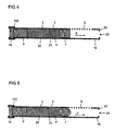
- FIG. 4 shows a schematic sectional view of a modification of the in the FIG. 1 shown reservoirs 2, in which, in contrast to FIG. 1 the closure element 7 is not spherical but is in the form of a cylinder, preferably in the form of a circular cylinder.
- FIG. 5 shows in a schematic cross-sectional view of a modification of the in FIG. 1 shown reservoirs 2, in contrast to FIG. 1 the Closure element 7 is not spherical but is in the form of a flattened ball, in particular in the form of an ellipsoid.
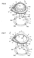
- FIG. 6 shows a diffuser 13 of an airbag module according to the invention with a section of an airbag 1 in an exploded view
- said diffuser 13 is cap-shaped and for fixing to a module housing of an airbag module has an annular peripheral flange 12, protrude from the bolt 120, which is set up and provided are to pass through openings of a module housing or other part of an airbag module for mounting the diffuser 13 on that airbag module.
- those bolts 120 protrude counter to a main deployment direction H of the airbag 1, along which the airbag 1 unfolds when inflated in the direction of an occupant to be protected.
- the flange 12 is located from the interior I of the airbag 1 ago with a side facing the airbag 12a on a the inlet opening 1a of the airbag 1 bordered edge region 1b, so that that edge region 1b of the inflow opening 1a of the airbag 1 when mounting the diffuser 13 on the airbag module , Is clamped in particular on a module housing of the airbag module between the flange 12 and that part of the airbag module.
- the edge region 1 b of the inflow opening 1 a of the airbag has through openings 120 a, which are penetrated by a respective bolt 120.
- a reservoir 2 of the type FIG. 1 arranged on a side facing away from the edge region 1b of the airbag 1 top 12b of the flange 12 of the diffuser 13 circulates openly annular, so that provided at the free end 10 of the first portion 4 of the reservoir 2 movement generating device 9 adjacent to the free end 16 of the second section 5 of the reservoir 2 is arranged, on which said end face 22 is formed with optional passage opening 23.
- the outflow openings 6 of the reservoir 2 are arranged on the wall 20 of the reservoir 2 in such a way that they face away from the edge region 1 b of the inflow opening 1 a of the airbag 1 or face the interior 1 of the airbag 1, so that the air from the reservoir 2 passes through the reservoir 2
- Outflow openings 6 liberated coolant 3 can be released by the shortest route in the interior I of the airbag 1.
- the reservoir 2 is according to FIG. 6 as a separate component to the flange 12 releasably (eg detent or screw) or unsolvable (eg rivet or weld) set.
- the reservoir 2 in one piece with the said flange 12, wherein in particular the wall 20 or the reservoir 2 itself can form the said flange 12.
- the bolts 120 are fixed directly to the wall 20 and the reservoir 2.
- FIG. 7 shows a schematic, perspective view of a modification of the in the FIG. 6 shown reservoir 2, wherein that reservoir 2 in contrast to FIG. 6 is not formed on a flange 12 of a diffuser 13, but on an annular circumferential clamping element 14 for the gas bag 1, from which the said bolts 120 for fixing the clamping element on an airbag module, in particular an airbag module housing, projecting against said main deployment direction H.
- the clamping element 14 serves to clamp the said edge region 1b of the airbag 1, which bounds and circulates the inflow opening 1a of the airbag 1, to a part of the airbag module, in particular to an airbag module housing.
- the clamping element 14 presses as before the flange 12 according to FIG. 6 from the interior I of the airbag 1 ago against the edge region 1 b of the inflow opening 1 a, against an inner side of that edge region 1 b facing the interior I.
- the reservoir 2 is fixed to the revolving clamping element 14 as a separate component and circulates openly along the clamping element 14, so that the free end 10 with the motion generating device 9 fixed thereto adjoins the end face 22 or the free end 16 of the second section 5 of the reservoir 2 is arranged.
- the free end 10 with the motion generating device 9 fixed thereto adjoins the end face 22 or the free end 16 of the second section 5 of the reservoir 2 is arranged.
- possible types of connection between reservoir 2 and clamping element 14 is to the comments too FIG. 6 directed.
- the reservoir 2 in one piece to the circumferential clamping element 14.
- the reservoir 2 itself form that clamping element 14, in which case the bolt 120 directly to a the Edge region 1b of the airbag 1 facing bottom of the reservoir 2 are fixed.
- the reservoir 2 is detachably fastened to the flange 12 of the diffuser 13 or to the circumferential clamping element (clamping ring) 14, it is advantageously possible to retrofit a conventional driver airbag module with such a reservoir 2 of an airbag module according to the invention.
- FIG. 8 shows in connection with FIG. 9 a schematic perspective view of an airbag module in the form of a passenger airbag module, with a rectangular module housing 11 which forms a receptacle A for a folded (not inflated) airbag 1 (in the FIG. 8 not shown), wherein that module housing 11 has a flat bottom 15, which serves the clamping of an inlet opening 1 a of the airbag 1 bordering edge region 1b.
- This may be related to the description of the one FIG. 7 mentioned clamping element, which has been adjusted accordingly.
- 11 through openings 11 c are provided on the said edge region 11 b of the module housing, which can be penetrated by suitable fastening means, such as screws.
- the mentioned motor vehicle part may in particular be an instrument panel of a motor vehicle.
- the bottom 15 of the module housing 11 has a trough-shaped recess 20, in which a gas generator 300 can be arranged, which serves to inflate the gas bag 1 to be arranged in the receptacle A.
- a gas generator 300 can be arranged on both sides of the trough-shaped depression 20
- barrel-shaped elevations 310 are arranged which partially surround the gas generator 300 in the main deployment direction H, ie, circulate transversely to the main deployment direction H sections, and of a part of the inflow opening 1a of Airbag 1 bordering edge region 1b are overlapped.
- a coolant 3 stored in a reservoir 2 is provided, that reservoir 2 being in the manner of FIG.
- FIG. 1 a first section 4 and a second section 5, wherein the said coolant 3 in the first section 4 and the at least one outflow opening 6 are provided for the outflow of the coolant 3 in the second section 5 of the reservoir 2.
- Those two sections 4, 5 are in the manner of FIG. 1 sealingly separated from each other by a closure element 7, said closure element 7 being displaced along a direction of movement E past the outflow openings 6 in the manner already described by means of a movement-generating device 9 provided at a free end 10 of the first section 4 of the reservoir 2 an end position can be moved, in which the closure element 7 according to FIG. 3 is arranged at a free end 16 of the second portion or an end face 22 of the reservoir 2 formed at this position.
- this reservoir 2 has a curvature, so that the second section 5, on which the said outflow openings 6 are formed, runs essentially transversely to the first section 4 of the reservoir 2, in which the coolant 3 is stored.
- the second section 5 with its outflow openings 6 so through a provided in a barrel-shaped elevation 310 through opening 15a in the limited by the module housing 11 receptacle A inside that the outflow 6 along the main deployment direction H faces an inflow opening of the gas bag to be arranged in the receptacle A.
- coolant 3 released through the outflow openings 6 can be released directly into an interior space of said airbag as described above.
- FIG. 10 shows in connection with the FIGS. 11 to 17 schematic representation of the preparation of a reservoir 2 in the manner of FIG. 1 ,
- the preparation of the other variants of the reservoir 2 proceeds in an analogous manner.
- a tube 2a extending along the later movement direction E is provided in a certain length and curvature (as required), said tube 2a having a wall 20 longitudinally extended along the later movement direction E, which is transverse to the direction of movement E rotates (the direction of movement E thus coincides with the extension direction of the tube 2a and the reservoir 2).
- this wall 20 in a transverse to the direction of movement E cross-sectional plane corresponding dimensions.
- Said tube 2a has two free ends 10, 16, which lie opposite each other along the direction of movement E and each delimit an opening 17a, 17b.
- a plurality of outflow openings 6 are formed. These can be stamped into the tube 2a, for which purpose an abutment element 200 is positively inserted into the tube 2a through the opening 17b formed at the free end 16 of the second section 5 (counter to the direction of movement E) so that the tube 2a does not undergo indentation when the outflow openings 6 are punched into the second section 5 of the tube 2a.
- a closure element 7 in the form of a ball (other shapes are also possible) introduced through the opening 17b of the free end 16 of the second portion 5 of the tube 2a in the tube 2a (pressed), in an initial position, in the the closure element 7, the second section 5 from the first portion 4 of the tube 2a sealingly divides.
- the free end 16 of the second Section 5 narrows, by folding (crimping) said free end.
- coolant 3 is introduced into the reservoir 2, and according to FIG. 16 along the later movement direction E introduced a movement generating device 9 having a widened end portion, which is supported along a circumferential direction of the step 50 seal 100 along the direction of movement E at said stage 50.
- that seal 100 has a side, via which the seal 100 rests against the circumferential step 50 and a side facing away from this circumferential side, over which the seal 100 bears against the widened region of the movement-generating device 9.
- the free end 10 is clamped to the widened region of the movement generating device 9 (by crimping / crimping), so that a peripheral edge of the free end 10 engages behind the widened region of the movement generating device 9, so that the movement generating device 9 is held against and along the direction of movement E of the closure element 7 in the free end 10 of the first section 4 of the reservoir (tube) 2a (cf. FIG. 17 ).
- FIG. 18 shows a schematic sectional view of a modification of the in the FIG. 1 shown reservoir 2 of an airbag module according to the invention, in which, in contrast to FIG. 1 a further closure means 77 is provided in the form of a ball (the further closure means 77 may also have one of the other shapes and properties described above).
- the further closure means 77 is arranged in the first section 4 of the reservoir 2 such that the coolant 3 is trapped along the direction of movement E between the two closure means 7, 77.
- the further closure means 77 is thus arranged along the direction of movement E between the movement-generating device 9 and the coolant 3 and thus functions as a piston for pushing out the coolant 3 from the reservoir 2.
- the movement generating device 9 pressurizes the further closure means 77 with a pressure
- the further closure means 77 is pushed out of its initial position in the direction of the outflow openings 6, taking along the coolant 3, which in turn carries the one closure means 7 and moves past the outflow openings 6, so that it comes to rest on the end face 22 of the reservoir 2.
- the pressurized further closure element 77 now pushes the coolant out of the reservoir 2 through the outflow openings 6.
- the closure element 77 arranged adjacent to the free end 10 of the first section 4 has, in addition to the seal upon activation of the cooling device 2, 3, 9, 7, 77, the function of a piston which pushes the coolant 3 out of the outflow openings 6 of the reservoir 2.
- the additional closure element 77 thus separates the resulting gases from the coolant 3 during the ignition of the motion generating device 9 (gas generator), which can thus develop its cooling effect immediately upon release, which manifests itself in significantly shorter times up to a certain pressure drop in the gas bag. Without this further closure element 77, the pressure drop retarding mixing of the gases of the movement generating device 9 with the coolant 3 takes place.
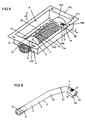
- FIG. 19 a modification of the in the FIG. 6 shown airbag module, in contrast to FIG. 6 the reservoir 2 has a curvature (angling) in the first section 4, so that a section 4 'of the reservoir 2, which comprises the free end 10 of the first section 4 of the reservoir 2 and the movement generating device 9, protrudes from the airbag 1.
- the curvature is formed so that the portion 4 'of the reservoir 2 is parallel to the bolts 120 and perpendicular to the bottom 12a of the flange 12. Or in other words, said portion 4' of the reservoir 2 extends along the main deployment direction H.
- the reservoir 2 is different from the FIG. 6 according to FIG. 18 constructed, that is, the coolant 3 is, as stated above, between the closure means 7, 77 enclosed.
- the reservoir 2 according to FIG. 19 curved and extends (rotates) along the flange 12, wherein the second portion 5 extends along the flange 12. Also extends that part of the first section 4, which contains the coolant 3 - this is trapped between the closure elements 7, 77 - along the flange 12. From this is the said section 4 ', which protrudes from the airbag 1 extends.
- the gas bag 1 is in the Fig. 19 not shown. This is on the FIG. 6 directed.
Landscapes
- Physics & Mathematics (AREA)
- Fluid Mechanics (AREA)
- Engineering & Computer Science (AREA)
- Mechanical Engineering (AREA)
- Air Bags (AREA)
Claims (15)
- Module d'airbag pour un véhicule automobile, comprenant- un sac à gaz (1), qui est susceptible d'être gonflé par admission de gaz dans le sac à gaz (1) pour la protection d'une personne,- un réservoir (2) à ouvrir pour stocker un agent de refroidissement (3), le réservoir (2) comprenant un premier tronçon (4) et un second tronçon (5) relié à celui-ci,- au moins une ouverture d'échappement (6) du réservoir (2) réalisée dans le second tronçon (5) et à travers laquelle l'agent de refroidissement (3) peut sortir hors du réservoir (2) pour refroidir les gaz admis dans le sac à gaz (1), et- un élément obturateur (7) pour obturer l'ouverture d'échappement (6),caractérisé en ce que
l'élément obturateur (7) subdivise le réservoir (2) dans les deux tronçons (4, 5), et en ce que l'agent de refroidissement (3) est agencé dans le premier tronçon (4), l'élément obturateur (7) fermant de façon étanche le premier tronçon (4) du réservoir (2) par rapport au second tronçon (5) du réservoir (2). - Module d'airbag selon la revendication 1, caractérisé en ce que l'élément obturateur (7) est déplaçable dans le réservoir (2) pour ouvrir l'ouverture d'échappement (6) et est agencé dans le réservoir (2) également dans l'état ouvert de l'ouverture d'échappement (6).
- Module d'airbag selon l'une des revendications précédentes, caractérisé en ce que l'élément obturateur (7) est déplaçable, le long d'une direction de déplacement (E) à partir d'une position initiale dans laquelle l'élément obturateur (7) subdivise le réservoir (2) dans les deux tronçons (4, 5), jusque dans une position finale dans laquelle l'agent de refroidissement (3) peut sortir hors du réservoir (2) en provenant du premier tronçon (4) via le second tronçon (5) et à travers ladite au moins une ouverture d'échappement (6).
- Module d'airbag selon la revendication 3, caractérisé en ce que le réservoir (2) comporte une paroi (20) allongée le long de la direction de déplacement (E), qui décrit une circonférence transversalement à la direction de déplacement (E), ladite paroi (20) étant en particulier réalisée au moins partiellement en forme de cylindre creux.
- Module d'airbag selon les revendications 3 et 4, caractérisé en ce que l'ouverture d'échappement (6) est réalisée sur la paroi (20), de sorte que l'agent de refroidissement (3) est chassé hors du réservoir (2) à travers ladite ouverture d'échappement (6) transversalement à la direction de déplacement (E).
- Module d'airbag selon l'une des revendications précédentes, caractérisé en ce que l'élément obturateur (7) est réalisé pour être déformable, en particulier déformable élastiquement.
- Module d'airbag selon la revendication 3 ou selon l'une des revendications 4 à 6 prises en dépendance de la revendication 3, caractérisé par un dispositif de génération de mouvement (9) qui est conçu et prévu pour mettre l'agent de refroidissement (3) sous pression, de sorte que l'agent de refroidissement (3) pousse l'élément obturateur (7) hors de la position initiale jusque dans la position finale.
- Module d'airbag selon la revendication 7, caractérisé en ce que le dispositif de génération de mouvement (9) est formé par un générateur de gaz qui est serti en particulier avec une extrémité libre (10) du premier tronçon (4) du réservoir (2).
- Module d'airbag selon l'une des revendications 1 à 8, caractérisé en ce qu'il est prévu un autre élément obturateur (77), qui est déplaçable à partir d'une position initiale dans laquelle l'autre élément obturateur (77) est agencé de telle façon que l'agent de refroidissement (3) soit enfermé entre les deux éléments obturateurs (7, 77), jusque dans une position finale, tel que l'autre élément obturateur (77) entraîne, lors de son déplacement vers sa position finale, l'agent de refroidissement (3) et le premier élément obturateur (7) pour libérer l'agent de refroidissement (3).
- Module d'airbag selon les revendications 3, 7 et 9, caractérisé en ce que le dispositif de génération de mouvement (9) est conçu et prévu pour mettre l'agent de refroidissement (3) sous pression via l'autre élément obturateur (77), de sorte que l'autre élément obturateur (77) force l'agent de refroidissement (31) hors du réservoir (2) et pousse ici le premier élément obturateur (7) hors de sa position initiale jusque dans sa position finale.
- Procédé pour fabriquer un module d'airbag, en particulier selon l'une des revendications 1 à 10, comprenant les étapes suivantes :- préparation d'un tube (2a), s'étendant le long d'une direction d'extension (E), qui est subdivisé le long de la direction d'extension (E) en un premier tronçon et en un second tronçon (4, 5),- réalisation d'au moins une ouverture d'échappement (6) seulement sur le second tronçon (5), et- introduction d'un élément obturateur (7) dans le tube (2a), de sorte que l'élément obturateur (7) subdivise le tube (2a) dans le premier et le second tronçon (4, 5), et- on remplit un agent de refroidissement (3) dans le premier tronçon (4), en particulier à travers une ouverture (17a) du premier tronçon (4), laquelle est bordée par l'extrémité libre (10) du premier tronçon (4).
- Procédé selon la revendication 11, caractérisée en ce qu'un élément déformable, en particulier déformable élastiquement, est introduit dans le tube (2a) à titre d'élément obturateur (7) qui ferme de façon étanche le premier tronçon (4) vis-à-vis du second tronçon (5), de sorte que l'agent de refroidissement (7) qui se trouve dans le premier tronçon (4) ne puisse pas sortir hors de ladite au moins une ouverture d'échappement (6) réalisée sur le second tronçon (5).
- Procédé selon l'une des revendications 11 et 12, caractérisé en ce qu'une extrémité libre (16) du second tronçon (5), qui est située à l'opposé, le long de la direction d'extension (E), de l'extrémité libre (10) du premier tronçon (4), est rétrécie pour empêcher que l'élément obturateur (7) puisse être forcé hors du tube (2a) le long de la direction d'extension (E).
- Procédé selon l'une des revendications 11 à 13, caractérisé en ce qu'un autre élément obturateur (77) est introduit dans le premier tronçon (4), en particulier à travers une ouverture (17a) du premier tronçon (4) qui est bordée par l'extrémité libre (10) du premier tronçon (4), de sorte que les deux éléments obturateurs (7, 77) enferment l'agent de refroidissement (3).
- Procédé selon l'une des revendications 13 et 14, caractérisé en ce que le dispositif de génération de mouvement (9) est introduit dans le premier tronçon (4) du tube (2a), en particulier à travers ladite ouverture (19a) du premier tronçon (4) et, après l'introduction dans le premier tronçon (4), le dispositif de génération de mouvement (9) est en particulier immobilisé sur celui-ci.
Applications Claiming Priority (3)
| Application Number | Priority Date | Filing Date | Title |
|---|---|---|---|
| DE102008036515 | 2008-08-06 | ||
| DE102008056948A DE102008056948A1 (de) | 2008-08-06 | 2008-11-07 | Airbagmodul für ein Kraftfahrzeug |
| PCT/EP2009/060022 WO2010015595A1 (fr) | 2008-08-06 | 2009-08-03 | Module d’airbag pour un véhicule automobile |
Publications (2)
| Publication Number | Publication Date |
|---|---|
| EP2176096A1 EP2176096A1 (fr) | 2010-04-21 |
| EP2176096B1 true EP2176096B1 (fr) | 2011-09-21 |
Family
ID=41528260
Family Applications (1)
| Application Number | Title | Priority Date | Filing Date |
|---|---|---|---|
| EP09781415A Not-in-force EP2176096B1 (fr) | 2008-08-06 | 2009-08-03 | Module d airbag pour un véhicule automobile |
Country Status (7)
| Country | Link |
|---|---|
| US (1) | US8136836B2 (fr) |
| EP (1) | EP2176096B1 (fr) |
| JP (1) | JP4809504B2 (fr) |
| CN (1) | CN101945783B (fr) |
| AT (1) | ATE525251T1 (fr) |
| DE (1) | DE102008056948A1 (fr) |
| WO (1) | WO2010015595A1 (fr) |
Families Citing this family (4)
| Publication number | Priority date | Publication date | Assignee | Title |
|---|---|---|---|---|
| DE102007046824A1 (de) * | 2007-09-26 | 2009-04-09 | Takata-Petri Ag | Aufblaseinrichtung für ein Airbagmodul |
| DE102008052481B4 (de) * | 2008-10-17 | 2012-04-26 | Takata-Petri Ag | Gasgeneratorbaugruppe für ein Kraftfahrzeug |
| JP5739777B2 (ja) * | 2011-09-21 | 2015-06-24 | タカタ株式会社 | エアバッグ用冷却剤放出装置及びエアバッグ装置 |
| FR2998846B1 (fr) * | 2012-12-04 | 2016-04-01 | Autoliv Dev | Generateur de gaz adaptatif pour coussin de protection |
Family Cites Families (16)
| Publication number | Priority date | Publication date | Assignee | Title |
|---|---|---|---|---|
| US3305319A (en) * | 1965-04-02 | 1967-02-21 | James F Kowalick | Propellant gas generator |
| JPS52121291A (en) * | 1976-04-01 | 1977-10-12 | Nippon Oil & Fats Co Ltd | Automatically inflated rescue buoyant apparatus |
| DE4440247A1 (de) | 1994-11-11 | 1996-05-15 | Dynamit Nobel Ag | Flüssiggasgenerator |
| DE19600279C1 (de) * | 1996-01-05 | 1997-06-26 | Daimler Benz Ag | Druckgasbehälter für einen Airbag |
| DE19618028A1 (de) | 1996-05-04 | 1997-11-06 | Mst Automotive Gmbh | Vorrichtung zum Aufblasen eines Airbags (III) |
| US5669631A (en) * | 1996-11-18 | 1997-09-23 | Morton International, Inc. | Liquid propellant airbag inflator with auto injection combustion chamber |
| DE19726296A1 (de) * | 1997-06-20 | 1998-12-24 | Temic Bayern Chem Airbag Gmbh | Gasgenerator mit Kühlvorrichtung |
| DE19726276A1 (de) * | 1997-06-20 | 1998-12-24 | Temic Bayern Chem Airbag Gmbh | Gasgenerator mit einer Vorrichtung zur Erzeugung eines Fluidfilms |
| JPH11129858A (ja) | 1997-10-31 | 1999-05-18 | Fuji Heavy Ind Ltd | 車両用エアバッグのインフレータ |
| US6076468A (en) * | 1998-03-26 | 2000-06-20 | Atlantic Research Corporation | Solid propellant/water type hybrid gas generator |
| US20050082804A1 (en) | 2003-10-17 | 2005-04-21 | Khandhadia Paresh S. | Filterless airbag module |
| DE202005016457U1 (de) * | 2005-10-17 | 2006-01-19 | Takata-Petri Ag | Airbagmodul für ein Kraftfahrzeug |
| DE102006010953A1 (de) * | 2006-03-03 | 2007-09-06 | Takata-Petri Ag | Airbagmodul für ein Kraftfahrzeug |
| FR2902060B1 (fr) * | 2006-06-09 | 2008-09-05 | Livbag Soc Par Actions Simplif | "generateur pyrotechnique de gaz utilise en securite automobile" |
| DE102007037604A1 (de) | 2007-08-07 | 2009-02-12 | Takata-Petri Ag | Airbagmodul für ein Kraftfahrzeug |
| DE102008010740B3 (de) * | 2008-02-21 | 2009-05-07 | Takata-Petri Ag | Airbagmodul für ein Kraftfahrzeug |
-
2008
- 2008-11-07 DE DE102008056948A patent/DE102008056948A1/de not_active Ceased
-
2009
- 2009-08-03 JP JP2011501251A patent/JP4809504B2/ja not_active Expired - Fee Related
- 2009-08-03 WO PCT/EP2009/060022 patent/WO2010015595A1/fr not_active Ceased
- 2009-08-03 CN CN200980106088.2A patent/CN101945783B/zh not_active Expired - Fee Related
- 2009-08-03 AT AT09781415T patent/ATE525251T1/de active
- 2009-08-03 EP EP09781415A patent/EP2176096B1/fr not_active Not-in-force
-
2010
- 2010-12-13 US US12/966,979 patent/US8136836B2/en not_active Expired - Fee Related
Also Published As
| Publication number | Publication date |
|---|---|
| JP2011515275A (ja) | 2011-05-19 |
| US20110079993A1 (en) | 2011-04-07 |
| JP4809504B2 (ja) | 2011-11-09 |
| US8136836B2 (en) | 2012-03-20 |
| ATE525251T1 (de) | 2011-10-15 |
| DE102008056948A1 (de) | 2010-02-18 |
| CN101945783B (zh) | 2012-12-12 |
| EP2176096A1 (fr) | 2010-04-21 |
| CN101945783A (zh) | 2011-01-12 |
| WO2010015595A1 (fr) | 2010-02-11 |
Similar Documents
| Publication | Publication Date | Title |
|---|---|---|
| DE69004355T2 (de) | Leichtbaugehäuse für Aufblasvorrichtungen auf der Beifahrerseite. | |
| EP0798168B1 (fr) | Dispositif de protection contre le choc latéral pour les occupants d'un véhicule | |
| DE102011051318B4 (de) | Interne airbag-vorrichtung | |
| DE4304919B4 (de) | Airbag-Vorrichtung im Bereich eines Dachrahmens eines Fahrzeugs | |
| DE69300496T2 (de) | Reaktionsdose mit kreisförmigem Diffusor. | |
| DE102007052246A1 (de) | Airbag, insbesondere für einen Kraftwagen | |
| DE69608472T2 (de) | Airbagmodul mit zylindrischem Aufbau | |
| DE19726782A1 (de) | Airbag-Vorrichtung | |
| DE102012018450A1 (de) | Personenkraftwagen mit einem sich am Fahrzeughimmel abstützenden Gassack eines Beifahrer- Frontgassackmoduls und Gassack für einen solchen Personenkraftwagen | |
| EP2176096B1 (fr) | Module d airbag pour un véhicule automobile | |
| EP1896299A1 (fr) | Ensemble coussin gonflable pour un module d'airbag d'un vehicule automobile | |
| DE102004026313A1 (de) | Überkopf-Airbagsystem | |
| WO2020030780A1 (fr) | Dispositif de commande de coussin gonflable, ainsi que système de coussin gonflable | |
| DE102017214953A1 (de) | Kraftfahrzeug-Insassenschutz | |
| DE10039800B4 (de) | Fahrzeugdach, insbesondere für ein Kraftfahrzeug | |
| DE102008052480B4 (de) | Fahrzeugsitzanordnung für ein Kraftfahrzeug | |
| EP2190699A1 (fr) | Ensemble chambre de combustion pour module sac gonflable | |
| DE102012007406A1 (de) | Airbageinrichtung | |
| DE102009014687B4 (de) | Insassenschutzvorrichtung für ein Kraftfahrzeug | |
| EP2495138B1 (fr) | Boîtier d'airbag doté d'une structure de générateur intégrée | |
| WO2020088920A1 (fr) | Moyen de support pouvant être rempli de gaz pour un véhicule automobile et véhicule automobile équipé de celui-ci | |
| DE102006016155B4 (de) | Schutzvorrichtung in Kraftfahrzeugen zum Personenschutz | |
| DE19732069C2 (de) | Airbagmodul | |
| EP1854679B1 (fr) | Direction comprenant un sac gonflable pour véhicule à moteur | |
| DE102004005555A1 (de) | Airbag-Modul |
Legal Events
| Date | Code | Title | Description |
|---|---|---|---|
| PUAI | Public reference made under article 153(3) epc to a published international application that has entered the european phase |
Free format text: ORIGINAL CODE: 0009012 |
|
| 17P | Request for examination filed |
Effective date: 20100309 |
|
| AK | Designated contracting states |
Kind code of ref document: A1 Designated state(s): AT BE BG CH CY CZ DE DK EE ES FI FR GB GR HR HU IE IS IT LI LT LU LV MC MK MT NL NO PL PT RO SE SI SK SM TR |
|
| AX | Request for extension of the european patent |
Extension state: AL BA RS |
|
| RIN1 | Information on inventor provided before grant (corrected) |
Inventor name: ISERMANN, PATRICK Inventor name: PURUSHOTHAMAN, PAARTHIBAN Inventor name: SCHREIBER, CHRISTIAN |
|
| GRAP | Despatch of communication of intention to grant a patent |
Free format text: ORIGINAL CODE: EPIDOSNIGR1 |
|
| GRAS | Grant fee paid |
Free format text: ORIGINAL CODE: EPIDOSNIGR3 |
|
| DAX | Request for extension of the european patent (deleted) | ||
| GRAA | (expected) grant |
Free format text: ORIGINAL CODE: 0009210 |
|
| AK | Designated contracting states |
Kind code of ref document: B1 Designated state(s): AT BE BG CH CY CZ DE DK EE ES FI FR GB GR HR HU IE IS IT LI LT LU LV MC MK MT NL NO PL PT RO SE SI SK SM TR |
|
| REG | Reference to a national code |
Ref country code: GB Ref legal event code: FG4D Free format text: NOT ENGLISH |
|
| REG | Reference to a national code |
Ref country code: CH Ref legal event code: EP |
|
| REG | Reference to a national code |
Ref country code: IE Ref legal event code: FG4D Free format text: LANGUAGE OF EP DOCUMENT: GERMAN |
|
| REG | Reference to a national code |
Ref country code: DE Ref legal event code: R096 Ref document number: 502009001413 Country of ref document: DE Effective date: 20111201 |
|
| REG | Reference to a national code |
Ref country code: NL Ref legal event code: VDEP Effective date: 20110921 |
|
| PG25 | Lapsed in a contracting state [announced via postgrant information from national office to epo] |
Ref country code: NO Free format text: LAPSE BECAUSE OF FAILURE TO SUBMIT A TRANSLATION OF THE DESCRIPTION OR TO PAY THE FEE WITHIN THE PRESCRIBED TIME-LIMIT Effective date: 20111221 Ref country code: LT Free format text: LAPSE BECAUSE OF FAILURE TO SUBMIT A TRANSLATION OF THE DESCRIPTION OR TO PAY THE FEE WITHIN THE PRESCRIBED TIME-LIMIT Effective date: 20110921 Ref country code: SE Free format text: LAPSE BECAUSE OF FAILURE TO SUBMIT A TRANSLATION OF THE DESCRIPTION OR TO PAY THE FEE WITHIN THE PRESCRIBED TIME-LIMIT Effective date: 20110921 Ref country code: FI Free format text: LAPSE BECAUSE OF FAILURE TO SUBMIT A TRANSLATION OF THE DESCRIPTION OR TO PAY THE FEE WITHIN THE PRESCRIBED TIME-LIMIT Effective date: 20110921 Ref country code: HR Free format text: LAPSE BECAUSE OF FAILURE TO SUBMIT A TRANSLATION OF THE DESCRIPTION OR TO PAY THE FEE WITHIN THE PRESCRIBED TIME-LIMIT Effective date: 20110921 |
|
| LTIE | Lt: invalidation of european patent or patent extension |
Effective date: 20110921 |
|
| PG25 | Lapsed in a contracting state [announced via postgrant information from national office to epo] |
Ref country code: SI Free format text: LAPSE BECAUSE OF FAILURE TO SUBMIT A TRANSLATION OF THE DESCRIPTION OR TO PAY THE FEE WITHIN THE PRESCRIBED TIME-LIMIT Effective date: 20110921 Ref country code: LV Free format text: LAPSE BECAUSE OF FAILURE TO SUBMIT A TRANSLATION OF THE DESCRIPTION OR TO PAY THE FEE WITHIN THE PRESCRIBED TIME-LIMIT Effective date: 20110921 Ref country code: GR Free format text: LAPSE BECAUSE OF FAILURE TO SUBMIT A TRANSLATION OF THE DESCRIPTION OR TO PAY THE FEE WITHIN THE PRESCRIBED TIME-LIMIT Effective date: 20111222 Ref country code: CY Free format text: LAPSE BECAUSE OF FAILURE TO SUBMIT A TRANSLATION OF THE DESCRIPTION OR TO PAY THE FEE WITHIN THE PRESCRIBED TIME-LIMIT Effective date: 20110921 |
|
| REG | Reference to a national code |
Ref country code: IE Ref legal event code: FD4D |
|
| PG25 | Lapsed in a contracting state [announced via postgrant information from national office to epo] |
Ref country code: IE Free format text: LAPSE BECAUSE OF FAILURE TO SUBMIT A TRANSLATION OF THE DESCRIPTION OR TO PAY THE FEE WITHIN THE PRESCRIBED TIME-LIMIT Effective date: 20110921 Ref country code: SK Free format text: LAPSE BECAUSE OF FAILURE TO SUBMIT A TRANSLATION OF THE DESCRIPTION OR TO PAY THE FEE WITHIN THE PRESCRIBED TIME-LIMIT Effective date: 20110921 Ref country code: CZ Free format text: LAPSE BECAUSE OF FAILURE TO SUBMIT A TRANSLATION OF THE DESCRIPTION OR TO PAY THE FEE WITHIN THE PRESCRIBED TIME-LIMIT Effective date: 20110921 Ref country code: IS Free format text: LAPSE BECAUSE OF FAILURE TO SUBMIT A TRANSLATION OF THE DESCRIPTION OR TO PAY THE FEE WITHIN THE PRESCRIBED TIME-LIMIT Effective date: 20120121 |
|
| PG25 | Lapsed in a contracting state [announced via postgrant information from national office to epo] |
Ref country code: PT Free format text: LAPSE BECAUSE OF FAILURE TO SUBMIT A TRANSLATION OF THE DESCRIPTION OR TO PAY THE FEE WITHIN THE PRESCRIBED TIME-LIMIT Effective date: 20120123 Ref country code: PL Free format text: LAPSE BECAUSE OF FAILURE TO SUBMIT A TRANSLATION OF THE DESCRIPTION OR TO PAY THE FEE WITHIN THE PRESCRIBED TIME-LIMIT Effective date: 20110921 Ref country code: NL Free format text: LAPSE BECAUSE OF FAILURE TO SUBMIT A TRANSLATION OF THE DESCRIPTION OR TO PAY THE FEE WITHIN THE PRESCRIBED TIME-LIMIT Effective date: 20110921 Ref country code: IT Free format text: LAPSE BECAUSE OF FAILURE TO SUBMIT A TRANSLATION OF THE DESCRIPTION OR TO PAY THE FEE WITHIN THE PRESCRIBED TIME-LIMIT Effective date: 20110921 Ref country code: EE Free format text: LAPSE BECAUSE OF FAILURE TO SUBMIT A TRANSLATION OF THE DESCRIPTION OR TO PAY THE FEE WITHIN THE PRESCRIBED TIME-LIMIT Effective date: 20110921 Ref country code: RO Free format text: LAPSE BECAUSE OF FAILURE TO SUBMIT A TRANSLATION OF THE DESCRIPTION OR TO PAY THE FEE WITHIN THE PRESCRIBED TIME-LIMIT Effective date: 20110921 |
|
| RAP2 | Party data changed (patent owner data changed or rights of a patent transferred) |
Owner name: TAKATA AG |
|
| REG | Reference to a national code |
Ref country code: DE Ref legal event code: R097 Ref document number: 502009001413 Country of ref document: DE |
|
| PLBE | No opposition filed within time limit |
Free format text: ORIGINAL CODE: 0009261 |
|
| STAA | Information on the status of an ep patent application or granted ep patent |
Free format text: STATUS: NO OPPOSITION FILED WITHIN TIME LIMIT |
|
| PG25 | Lapsed in a contracting state [announced via postgrant information from national office to epo] |
Ref country code: DK Free format text: LAPSE BECAUSE OF FAILURE TO SUBMIT A TRANSLATION OF THE DESCRIPTION OR TO PAY THE FEE WITHIN THE PRESCRIBED TIME-LIMIT Effective date: 20110921 |
|
| 26N | No opposition filed |
Effective date: 20120622 |
|
| REG | Reference to a national code |
Ref country code: DE Ref legal event code: R082 Ref document number: 502009001413 Country of ref document: DE Representative=s name: MAIKOWSKI & NINNEMANN PATENTANWAELTE, DE |
|
| REG | Reference to a national code |
Ref country code: DE Ref legal event code: R097 Ref document number: 502009001413 Country of ref document: DE Effective date: 20120622 |
|
| REG | Reference to a national code |
Ref country code: DE Ref legal event code: R081 Ref document number: 502009001413 Country of ref document: DE Owner name: TAKATA AKTIENGESELLSCHAFT, DE Free format text: FORMER OWNER: TAKATA-PETRI AG, 63743 ASCHAFFENBURG, DE Effective date: 20120904 Ref country code: DE Ref legal event code: R082 Ref document number: 502009001413 Country of ref document: DE Representative=s name: MAIKOWSKI & NINNEMANN PATENTANWAELTE, DE Effective date: 20120904 Ref country code: DE Ref legal event code: R082 Ref document number: 502009001413 Country of ref document: DE Representative=s name: MAIKOWSKI & NINNEMANN PATENTANWAELTE PARTNERSC, DE Effective date: 20120904 |
|
| BERE | Be: lapsed |
Owner name: TAKATA-PETRI A.G. Effective date: 20120831 |
|
| PG25 | Lapsed in a contracting state [announced via postgrant information from national office to epo] |
Ref country code: MC Free format text: LAPSE BECAUSE OF NON-PAYMENT OF DUE FEES Effective date: 20120831 |
|
| PG25 | Lapsed in a contracting state [announced via postgrant information from national office to epo] |
Ref country code: ES Free format text: LAPSE BECAUSE OF FAILURE TO SUBMIT A TRANSLATION OF THE DESCRIPTION OR TO PAY THE FEE WITHIN THE PRESCRIBED TIME-LIMIT Effective date: 20120101 |
|
| PG25 | Lapsed in a contracting state [announced via postgrant information from national office to epo] |
Ref country code: BE Free format text: LAPSE BECAUSE OF NON-PAYMENT OF DUE FEES Effective date: 20120831 |
|
| PG25 | Lapsed in a contracting state [announced via postgrant information from national office to epo] |
Ref country code: BG Free format text: LAPSE BECAUSE OF FAILURE TO SUBMIT A TRANSLATION OF THE DESCRIPTION OR TO PAY THE FEE WITHIN THE PRESCRIBED TIME-LIMIT Effective date: 20111221 |
|
| PG25 | Lapsed in a contracting state [announced via postgrant information from national office to epo] |
Ref country code: MT Free format text: LAPSE BECAUSE OF FAILURE TO SUBMIT A TRANSLATION OF THE DESCRIPTION OR TO PAY THE FEE WITHIN THE PRESCRIBED TIME-LIMIT Effective date: 20110921 |
|
| REG | Reference to a national code |
Ref country code: CH Ref legal event code: PL |
|
| GBPC | Gb: european patent ceased through non-payment of renewal fee |
Effective date: 20130803 |
|
| PG25 | Lapsed in a contracting state [announced via postgrant information from national office to epo] |
Ref country code: TR Free format text: LAPSE BECAUSE OF FAILURE TO SUBMIT A TRANSLATION OF THE DESCRIPTION OR TO PAY THE FEE WITHIN THE PRESCRIBED TIME-LIMIT Effective date: 20110921 Ref country code: LI Free format text: LAPSE BECAUSE OF NON-PAYMENT OF DUE FEES Effective date: 20130831 Ref country code: CH Free format text: LAPSE BECAUSE OF NON-PAYMENT OF DUE FEES Effective date: 20130831 |
|
| PG25 | Lapsed in a contracting state [announced via postgrant information from national office to epo] |
Ref country code: SM Free format text: LAPSE BECAUSE OF FAILURE TO SUBMIT A TRANSLATION OF THE DESCRIPTION OR TO PAY THE FEE WITHIN THE PRESCRIBED TIME-LIMIT Effective date: 20110921 Ref country code: LU Free format text: LAPSE BECAUSE OF NON-PAYMENT OF DUE FEES Effective date: 20120803 |
|
| PG25 | Lapsed in a contracting state [announced via postgrant information from national office to epo] |
Ref country code: HU Free format text: LAPSE BECAUSE OF FAILURE TO SUBMIT A TRANSLATION OF THE DESCRIPTION OR TO PAY THE FEE WITHIN THE PRESCRIBED TIME-LIMIT Effective date: 20090803 Ref country code: GB Free format text: LAPSE BECAUSE OF NON-PAYMENT OF DUE FEES Effective date: 20130803 |
|
| REG | Reference to a national code |
Ref country code: FR Ref legal event code: PLFP Year of fee payment: 7 |
|
| PG25 | Lapsed in a contracting state [announced via postgrant information from national office to epo] |
Ref country code: MK Free format text: LAPSE BECAUSE OF FAILURE TO SUBMIT A TRANSLATION OF THE DESCRIPTION OR TO PAY THE FEE WITHIN THE PRESCRIBED TIME-LIMIT Effective date: 20110921 |
|
| REG | Reference to a national code |
Ref country code: AT Ref legal event code: MM01 Ref document number: 525251 Country of ref document: AT Kind code of ref document: T Effective date: 20140803 |
|
| PG25 | Lapsed in a contracting state [announced via postgrant information from national office to epo] |
Ref country code: AT Free format text: LAPSE BECAUSE OF NON-PAYMENT OF DUE FEES Effective date: 20140803 |
|
| PGFP | Annual fee paid to national office [announced via postgrant information from national office to epo] |
Ref country code: FR Payment date: 20150629 Year of fee payment: 7 |
|
| REG | Reference to a national code |
Ref country code: FR Ref legal event code: ST Effective date: 20170428 |
|
| PG25 | Lapsed in a contracting state [announced via postgrant information from national office to epo] |
Ref country code: FR Free format text: LAPSE BECAUSE OF NON-PAYMENT OF DUE FEES Effective date: 20160831 |
|
| PGFP | Annual fee paid to national office [announced via postgrant information from national office to epo] |
Ref country code: DE Payment date: 20171030 Year of fee payment: 9 |
|
| REG | Reference to a national code |
Ref country code: DE Ref legal event code: R119 Ref document number: 502009001413 Country of ref document: DE |
|
| PG25 | Lapsed in a contracting state [announced via postgrant information from national office to epo] |
Ref country code: DE Free format text: LAPSE BECAUSE OF NON-PAYMENT OF DUE FEES Effective date: 20190301 |