EP2176554B1 - Dispositif de sécurité pour récipient contenant des fluides sous pression - Google Patents
Dispositif de sécurité pour récipient contenant des fluides sous pression Download PDFInfo
- Publication number
- EP2176554B1 EP2176554B1 EP08749412A EP08749412A EP2176554B1 EP 2176554 B1 EP2176554 B1 EP 2176554B1 EP 08749412 A EP08749412 A EP 08749412A EP 08749412 A EP08749412 A EP 08749412A EP 2176554 B1 EP2176554 B1 EP 2176554B1
- Authority
- EP
- European Patent Office
- Prior art keywords
- screw
- port
- closure
- safety device
- closure screw
- Prior art date
- Legal status (The legal status is an assumption and is not a legal conclusion. Google has not performed a legal analysis and makes no representation as to the accuracy of the status listed.)
- Active
Links
Images


Classifications
-
- F—MECHANICAL ENGINEERING; LIGHTING; HEATING; WEAPONS; BLASTING
- F15—FLUID-PRESSURE ACTUATORS; HYDRAULICS OR PNEUMATICS IN GENERAL
- F15B—SYSTEMS ACTING BY MEANS OF FLUIDS IN GENERAL; FLUID-PRESSURE ACTUATORS, e.g. SERVOMOTORS; DETAILS OF FLUID-PRESSURE SYSTEMS, NOT OTHERWISE PROVIDED FOR
- F15B1/00—Installations or systems with accumulators; Supply reservoir or sump assemblies
- F15B1/02—Installations or systems with accumulators
- F15B1/04—Accumulators
- F15B1/08—Accumulators using a gas cushion; Gas charging devices; Indicators or floats therefor
-
- F—MECHANICAL ENGINEERING; LIGHTING; HEATING; WEAPONS; BLASTING
- F16—ENGINEERING ELEMENTS AND UNITS; GENERAL MEASURES FOR PRODUCING AND MAINTAINING EFFECTIVE FUNCTIONING OF MACHINES OR INSTALLATIONS; THERMAL INSULATION IN GENERAL
- F16K—VALVES; TAPS; COCKS; ACTUATING-FLOATS; DEVICES FOR VENTING OR AERATING
- F16K1/00—Lift valves or globe valves, i.e. cut-off apparatus with closure members having at least a component of their opening and closing motion perpendicular to the closing faces
- F16K1/02—Lift valves or globe valves, i.e. cut-off apparatus with closure members having at least a component of their opening and closing motion perpendicular to the closing faces with screw-spindle
- F16K1/04—Lift valves or globe valves, i.e. cut-off apparatus with closure members having at least a component of their opening and closing motion perpendicular to the closing faces with screw-spindle with a cut-off member rigid with the spindle, e.g. main valves
-
- F—MECHANICAL ENGINEERING; LIGHTING; HEATING; WEAPONS; BLASTING
- F16—ENGINEERING ELEMENTS AND UNITS; GENERAL MEASURES FOR PRODUCING AND MAINTAINING EFFECTIVE FUNCTIONING OF MACHINES OR INSTALLATIONS; THERMAL INSULATION IN GENERAL
- F16K—VALVES; TAPS; COCKS; ACTUATING-FLOATS; DEVICES FOR VENTING OR AERATING
- F16K24/00—Devices, e.g. valves, for venting or aerating enclosures
- F16K24/04—Devices, e.g. valves, for venting or aerating enclosures for venting only
-
- F—MECHANICAL ENGINEERING; LIGHTING; HEATING; WEAPONS; BLASTING
- F15—FLUID-PRESSURE ACTUATORS; HYDRAULICS OR PNEUMATICS IN GENERAL
- F15B—SYSTEMS ACTING BY MEANS OF FLUIDS IN GENERAL; FLUID-PRESSURE ACTUATORS, e.g. SERVOMOTORS; DETAILS OF FLUID-PRESSURE SYSTEMS, NOT OTHERWISE PROVIDED FOR
- F15B2201/00—Accumulators
- F15B2201/40—Constructional details of accumulators not otherwise provided for
- F15B2201/415—Gas ports
- F15B2201/4155—Gas ports having valve means
-
- Y—GENERAL TAGGING OF NEW TECHNOLOGICAL DEVELOPMENTS; GENERAL TAGGING OF CROSS-SECTIONAL TECHNOLOGIES SPANNING OVER SEVERAL SECTIONS OF THE IPC; TECHNICAL SUBJECTS COVERED BY FORMER USPC CROSS-REFERENCE ART COLLECTIONS [XRACs] AND DIGESTS
- Y10—TECHNICAL SUBJECTS COVERED BY FORMER USPC
- Y10T—TECHNICAL SUBJECTS COVERED BY FORMER US CLASSIFICATION
- Y10T137/00—Fluid handling
- Y10T137/7069—With lock or seal
Definitions
- the invention relates to a safety device with container for enclosing pressure media, in particular in the form of hydropneumatic devices such as hydraulic accumulator, wherein at a filling or test port closure device as a screw with a threaded connection located on the threaded connector screw is present, which locks the connection when tightening the screw and releasing a flow path through the port upon release.
- a filling or test port closure device as a screw with a threaded connection located on the threaded connector screw is present, which locks the connection when tightening the screw and releasing a flow path through the port upon release.
- this procedure is such that the closure screw, for example by means of a manual actuated Allen key, only by a small amount, about the order of half a revolution, is solved. If this requirement is not met and the screw not only loosened, but turned out too far, there is a risk that the screw plug is thrown out of the container by gas pressure not yet released and, if there is no filling and testing device on the connection, which causes the Environment endangered and represents a corresponding accident risk for the staff. This danger exists especially if, instead of a manual turning tool, a driven tool, for example a cordless drill, is used.
- a generic safety device in the form of a closure for high-pressure gas tank wherein at a filling or test port as closure means a screw with a threaded connector located on the screw plug is present, which locks the connection when tightening the screw and when loosening a flow path through the connection releases, wherein a means in the form of an existing around the opening of the container stop, which cooperates with the underside of the screw plug, is present such that upon release of the screw, the movement of the screw plug is limited to a distance at which the threaded engagement is maintained.
- the present invention seeks to provide a safety device with container, which ensures increased safety over the known solutions, especially in the activities mentioned above, a threat to the environment.
- the connecting piece has a portion adjacent to the container interior with the threaded bore for the shaft of the screw plug and a subsequent section in the form of a hollow cylinder for receiving the head of the screw plug and that the blocking element anchored to the hollow cylinder so is that it forms into the interior of the hollow cylinder projecting abutment surfaces, which limit their movement from the closed position by starting the head of the screw plug.
- the distance of movement of the screw plug may preferably be limited to an end position in which between seal assembly and head of Placement screw is given such a distance that the flow path is formed for a media passage.
- the blocking element may for example be formed by a Zylinderkerbwind in the outer edge region of the hollow cylinder in the wall in sits a bore which is transverse to the cylinder axis.
- the blocking element is formed by a snap ring or a resilient retaining ring which sits in a formed in the outer edge region in the inner wall of the hollow cylinder annular groove.
- a device in addition to the blocking element as a further means for limiting the distance of movement of the screw plug, a device may be present which limits the transferable to the screw plug during release torque. Due to the limitation of the torque which can be applied when unscrewing the screw, the structural strength of the blocking element requires only particularly low requirements, so that, for example, short snap rings, which are particularly easy to assemble, can be used as a blocking element.
- the torque limiting device may be formed such that the head has a reduced outer diameter in its end portion to form a hex socket surrounding the hexagon socket, and the wall thickness of the sleeve is selected to exceed this a certain, acting on the wall of the hexagon socket torque shears off. After shearing the sleeve forming the wall of the hexagon socket no further torque can be transmitted to the screw head by means of a respective turning tool.
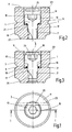
- a gas filling screw 1 is screwed as a closure element in a connection piece 3, on the gas side of a hydraulic accumulator not shown as filling connection for filling with a working gas, such as nitrogen gas, or as Test connection is provided. It is understood that the invention can equally be provided as a safety device for closure elements of another type.
- Fig. 1 to 3 show a first embodiment in which the connecting piece 3 has a generally circular cylindrical shape, wherein, concentric to the longitudinal axis 5, in which the gas side of the hydraulic accumulator, not shown end region, a threaded bore 7 is formed. On the other, outer end closes to the threaded hole 7 opposite to this extended inner hollow cylinder 9, which is also concentric to the axis 5 and at the outer end 11 of the connecting piece 3 is open. Within the hollow cylinder 9, the head 13 of the screw 1 is received. With the help of an in-head 13 hexagon socket 15, the screw 1 is screwed with its shaft 17 with the threaded hole 7, so that the screw 1 normally in Fig.
- the sealing arrangement consists of an outer soft iron ring 21 and an elastomeric ring 19 surrounding the shaft 17 of the screw 1.
- Fig. 3 shows that when unscrewing the screw 1, the shaft 17 of the screw 1 has moved in the threaded bore 7 to the outside, the distance of the displacement by the system at the as blocking element Serving cylinder block 25 in an in Fig. 3 limit position shown is limited.
- the lifting of the bottom of the head 13 of the screw 1 from the sealing element 19 leads to the release of a flow path, wherein the passage size determined by the extent of migration of the shaft 17 in the threaded hole 7.
- Cylinderkerb Due to the arrangement of acting as a blocking element Cylinderkerb turns 25 while the screw 1 is protected against ejection from the connecting piece 3, because by limiting the path length when unscrewing at least partially threaded access of the shaft 17 in the threaded hole 7 remains.
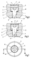
- the blocking element is formed in this embodiment by a snap ring 35 which is secured in an annular groove 37 which, as before the transverse bore 23, is arranged in the vicinity of the outer end 11 of the connecting piece 13.
- the annular groove 37 is incorporated in the inner wall of the hollow cylinder 9. Since the breaking of the snap ring 35 after the tightening of the screw 1 is carried out quickly and easily, this embodiment is characterized by a special ease of installation, the additional advantage of low production costs is given because snap rings of desired dimensions as common commercial goods are available inexpensively.
- Fig. 7 to 9 shown third embodiment which differs from the example described above only insofar when instead of an annular groove 37 with a circular groove cross-section now a corresponding annular groove 47 is provided, which has a rectangular groove cross-section and is provided for receiving a spring-locking ring 45. Since the other construction and operation is consistent with the other embodiments, a more detailed description is unnecessary. As already indicated, even with such a spring-locking ring 45 both a special ease of installation given and the advantage of low production costs, since such circlips 45 are also available inexpensively available as a commodity.
- the longitudinal narrow notch which is denoted by 20 in the preceding examples, is made longer and in FIGS. 11 and 12 denoted by 40.
- the length of the notch 40 is selected so that in the in Fig. 12 shown, open state of the screw, the notch 40 extends beyond the end 42 of the threads of the threaded hole 7 out so far that in the open state, the permeability is improved, so a lighter gas passage is enabled.
- an additional securing means is provided in this embodiment for the end position limiting when loosening the screw 1.
- a blocking element is also present here, which is formed by a snap ring 55 seated in an annular groove 37.
- a torque limiting device which limits the transferable to the screw plug 1 when releasing torque exists.
- FIGS. 11 and 12 show, for this purpose, the head 13 of the screw 1 is screwed in the hexagon socket 15 surrounding end portion, so that a side wall the hexagon socket 15 forming, relatively thin-walled sleeve 59 is formed.
- the wall thickness of the sleeve 59 is chosen so that when loosening the screw 1, when this in the in Fig.
- the sleeve 59 is sheared off, if an attempt is made to screw by increasing the torque even further screw out the screw 1. A further torque transmission is no longer possible after elimination of the hexagon socket 15 defining wall parts. Accordingly, since the maximum supporting force to be applied by the blocking element is limited, a short snap ring 55 can be used as the blocking element, in which the ring ends form a relatively large gap 46, see Fig. 10 , Such a snap ring 55 can be installed very quickly and easily.
Landscapes
- Engineering & Computer Science (AREA)
- General Engineering & Computer Science (AREA)
- Mechanical Engineering (AREA)
- Physics & Mathematics (AREA)
- Fluid Mechanics (AREA)
- Filling Or Discharging Of Gas Storage Vessels (AREA)
- Supply Devices, Intensifiers, Converters, And Telemotors (AREA)
- Pressure Vessels And Lids Thereof (AREA)
Abstract
Claims (7)
- Dispositif de sécurité à récipient pour enfermer des fluides sous pression, notamment sous la forme de dispositifs hydropneumatiques, comme des accumulateurs hydrauliques, dans lequel il y a sur un raccord de remplissage ou de contrôle, comme dispositif de fermeture, un vissage ayant une vis (1) de fermeture se trouvant en pénétration d'engrènement sur le raccord (3), obturant le raccord (3) lorsque le vissage est serré et dégageant un trajet d'écoulement dans le raccord (3) lorsqu'il est desserré, dans lequel il y a un moyen (25, 35, 45, 55, 59) qui, lors du desserrage du vissage, limite le mouvement de la vis (1) de fermeture à une étendue de trajet pour laquelle la pénétration d'engrènement reste conservée, la vis (1) de fermeture étant vissée avec une tubulure (3) de raccordement du récipient (1) et un élément (25, 35, 45, 55) de blocage, ancré dans la tubulure (3) de raccordement, étant prévu comme moyen qui limite l'étendue de trajet libre de la vis (1) de fermeture se déplaçant par rapport à un taraudage (7) de la tubulure (3), caractérisé en ce que la tubulure (3) de raccordement comporte un tronçon, voisin de l'intérieur du récipient et ayant le taraudage (7) pour le fût (17) de la vis (1) de fermeture, et un tronçon, s'y raccordant sous la forme d'un cylindre (9) creux, pour la réception de la tête (13) de la vis (1) de fermeture et en ce que l'élément (25, 35, 45, 55) de blocage est ancré dans le cylindre (9) creux de manière à former des surfaces de butée, qui font saillie à l'intérieur du cylindre (9) creux et qui, par application de la tête (13) de la vis (1) de fermeture, en limite le déplacement hors de la position de fermeture.
- Dispositif de sécurité suivant la revendication 1, caractérisé en ce qu'il est prévu, au fond du cylindre (9) creux au bord d'ouverture du taraudage (7), un agencement (19, 21) d'étanchéité, auquel, dans la position de fermeture, le côté inférieur de la tête (13) de la vis (1) de fermeture s'applique avec l'étanchéité et en ce que l'étendue de trajet du déplacement de la vis (1) de fermeture est limitée jusqu'à une position de fin de course telle qu'il y a entre l'agencement (19, 21) d'étanchéité et la tête (13) de la vis de fermeture une distance telle que le trajet d'écoulement pour un passage de fluide est formé.
- Dispositif de sécurité suivant la revendication 1 ou 2, caractérisé en ce que l'élément de blocage est formé par une broche (25) cylindrique à encoche, qui vient dans la partie de bord extérieur du cylindre (9) creux dans sa paroi dans un trou (23) qui s'étend transversalement à l'axe (5) du cylindre.
- Dispositif de sécurité suivant l'une des revendications 1 à 3, caractérisé en ce que l'élément de blocage est formé par un jonc (35, 55) ou par une bague (45) de sécurité élastique, qui vient, dans une rainure (37 et 47) annulaire formée dans une partie de bord extérieure de la paroi intérieure du cylindre (9) creux.
- Dispositif de sécurité suivant l'une des revendications 1 à 4, caractérisé en ce qu'en plus de l'élément (25, 35, 45, 55) de blocage, il y a comme autre moyen de limitation de l'étendue du trajet du déplacement de la vis (1) de fermeture, un dispositif (59) qui limite le couple de rotation pouvant être transmis au desserrage à la vis (1) de fermeture.
- Dispositif de sécurité suivant la revendication 5, caractérisé en ce que la vis (1) de fermeture a une tête (13) à six pans (15) intérieurs, en ce que la tête (13) a pour la formation d'un manchon (59) entourant le six pans (15) intérieur dans sa partie (61) d'extrémité, un diamètre extérieur diminué et en ce que l'épaisseur de paroi du manchon (59) est choisie de manière en ce que celui-ci se cisaille lors du dépassement d'un couple de rotation agissant sur la paroi du six pans (15) intérieur.
- Dispositif de sécurité suivant l'une des revendications 1 à 6, caractérisé en ce que la vis (1) de fermeture est une vis à remplissage de gaz qui prend assise dans une tubulure (3) de raccordement se trouvant comme raccord de remplissage du côté du gaz d'un accumulateur hydraulique.
Applications Claiming Priority (2)
| Application Number | Priority Date | Filing Date | Title |
|---|---|---|---|
| DE200710032207 DE102007032207A1 (de) | 2007-07-11 | 2007-07-11 | Sicherheitseinrichtung für Druckmedien einschließende Behälter |
| PCT/EP2008/003729 WO2009006961A1 (fr) | 2007-07-11 | 2008-05-09 | Dispositif de sécurité pour récipient contenant des fluides sous pression |
Publications (3)
| Publication Number | Publication Date |
|---|---|
| EP2176554A1 EP2176554A1 (fr) | 2010-04-21 |
| EP2176554B1 true EP2176554B1 (fr) | 2012-08-08 |
| EP2176554B8 EP2176554B8 (fr) | 2013-09-11 |
Family
ID=39687095
Family Applications (1)
| Application Number | Title | Priority Date | Filing Date |
|---|---|---|---|
| EP08749412.6A Active EP2176554B8 (fr) | 2007-07-11 | 2008-05-09 | Dispositif de sécurité pour récipient contenant des fluides sous pression |
Country Status (5)
| Country | Link |
|---|---|
| US (1) | US9534614B2 (fr) |
| EP (1) | EP2176554B8 (fr) |
| JP (1) | JP2010532846A (fr) |
| DE (1) | DE102007032207A1 (fr) |
| WO (1) | WO2009006961A1 (fr) |
Cited By (1)
| Publication number | Priority date | Publication date | Assignee | Title |
|---|---|---|---|---|
| EP4310371A1 (fr) | 2022-07-20 | 2024-01-24 | Oventrop GmbH & Co. KG | Robinet avec élément de soupape |
Families Citing this family (10)
| Publication number | Priority date | Publication date | Assignee | Title |
|---|---|---|---|---|
| EP2626571B1 (fr) * | 2012-02-08 | 2019-10-23 | Grundfos Holding A/S | Bague de serrage dotée d'une limitation de force |
| CN112543848B (zh) * | 2018-08-01 | 2023-10-13 | 法斯泰斯特公司 | 维修连接阀组件 |
| CN110397736B (zh) * | 2018-10-15 | 2024-03-22 | 沈阳工业大学 | 一种保证外壁平整的双向进出气门及其锁闭结构 |
| AT17019U1 (fr) * | 2019-08-28 | 2021-02-15 | Zieger Dipl Ing Andreas | |
| AT17069U1 (de) * | 2019-08-28 | 2021-04-15 | Andreas Zieger Dipl Ing | Manuell betätigtes ventil |
| IT201900019082A1 (it) * | 2019-10-16 | 2021-04-16 | Tapel Di Mastromatteo Ciro & C S A S | Rubinetto autopulente da esterno o da incasso |
| FR3109977A1 (fr) * | 2020-05-08 | 2021-11-12 | Cryl | Equipement de décompression sécurisé pour circuit hydraulique |
| KR102566784B1 (ko) * | 2021-04-29 | 2023-08-16 | (주)모토닉 | 수소 고압 레귤레이터용 안전밸브 장치 |
| KR102792537B1 (ko) * | 2022-04-28 | 2025-04-08 | 주식회사 금아하이드파워 | 피스톤 축압기용 가스밸브 안전 시스템 구조 |
| DE102024003459A1 (de) | 2024-10-21 | 2026-04-23 | Hydac Technology Gmbh | Hydraulischer Druckspeicher |
Family Cites Families (13)
| Publication number | Priority date | Publication date | Assignee | Title |
|---|---|---|---|---|
| DE68519C (de) | E. TH. FOERSTER in Berlin, Alte Jakobstr. 5 | Verschlufs an Behältern für Hochdruckgase | ||
| US1733309A (en) * | 1928-06-05 | 1929-10-29 | Leonard Charles Warren | Valve mechanism |
| US2827913A (en) * | 1955-07-28 | 1958-03-25 | Wagner William | Self-tapping valve for tubes, pipes, tanks and other conduits and containers |
| US3323546A (en) * | 1964-07-01 | 1967-06-06 | United Aircraft Prod | Hydraulic bleed valve |
| US3472427A (en) * | 1967-04-20 | 1969-10-14 | Pennsalt Chemicals Corp | Destructible valve |
| DE2000355A1 (de) * | 1970-01-07 | 1971-07-15 | Langen & Co | Hydrospeicher |
| DE2238356A1 (de) * | 1972-08-04 | 1974-02-14 | Fichtel & Sachs Ag | Fuellventil mit verschiebbarem ventilkoerper fuer hydropneumatische federungen von kraftfahrzeugen |
| US3865344A (en) * | 1972-10-25 | 1975-02-11 | Carrier Corp | Retaining ring |
| DE2551124A1 (de) * | 1975-11-14 | 1977-05-26 | Bosch Gmbh Robert | Fuellvorrichtung fuer den gasraum eines druckbehaelters |
| EP0047107B1 (fr) * | 1980-08-29 | 1984-07-11 | Brd Company Limited | Accouplement à cannelures |
| US4601305A (en) * | 1984-11-29 | 1986-07-22 | Nordskog Robert A | Compact gas compressor check valve |
| DE19511525C2 (de) * | 1995-03-29 | 1999-11-04 | Mannesmann Rexroth Ag | Hydrozylinder mit einer Funktionsschraube und einer Sicherung dafür |
| US5713705A (en) * | 1996-03-01 | 1998-02-03 | Gruenbichler; Carl | Fastener bolt with limited torque head |
-
2007
- 2007-07-11 DE DE200710032207 patent/DE102007032207A1/de not_active Withdrawn
-
2008
- 2008-05-09 EP EP08749412.6A patent/EP2176554B8/fr active Active
- 2008-05-09 WO PCT/EP2008/003729 patent/WO2009006961A1/fr not_active Ceased
- 2008-05-09 JP JP2010515356A patent/JP2010532846A/ja active Pending
- 2008-05-09 US US12/451,475 patent/US9534614B2/en active Active
Cited By (2)
| Publication number | Priority date | Publication date | Assignee | Title |
|---|---|---|---|---|
| EP4310371A1 (fr) | 2022-07-20 | 2024-01-24 | Oventrop GmbH & Co. KG | Robinet avec élément de soupape |
| DE102022118129A1 (de) | 2022-07-20 | 2024-01-25 | Oventrop Gmbh & Co. Kg | Armatur mit Ventilelement |
Also Published As
| Publication number | Publication date |
|---|---|
| JP2010532846A (ja) | 2010-10-14 |
| DE102007032207A1 (de) | 2009-01-15 |
| EP2176554A1 (fr) | 2010-04-21 |
| US20100126597A1 (en) | 2010-05-27 |
| US9534614B2 (en) | 2017-01-03 |
| EP2176554B8 (fr) | 2013-09-11 |
| WO2009006961A1 (fr) | 2009-01-15 |
Similar Documents
| Publication | Publication Date | Title |
|---|---|---|
| WO2009006961A1 (fr) | Dispositif de sécurité pour récipient contenant des fluides sous pression | |
| EP0608491B1 (fr) | Limiteur de pression à débit volumineux | |
| EP1934404B1 (fr) | Ancrage a tube de friction et adaptateur de gonflage pour celui-ci | |
| DE2756084C3 (de) | Schraubsicherung | |
| DE102014010570B4 (de) | Kupplungsteil für eine Kupplung für Druckmittelleitungen | |
| WO2018001561A1 (fr) | Soupape de réservoir | |
| DE102015222640B4 (de) | Kupplungselement und Ventilstößel für eine Kupplung zur Verbindung von Druckmittelleitungen | |
| DE102013009650A1 (de) | Ventil | |
| EP2529137B1 (fr) | Soupape de limitation de pression | |
| DE102015109278A1 (de) | Verbindungssystem, Klemmschraube, Verfahren zum Verbinden zweier Bauteile und Werkzeug zur Herstellung des Verbindungssystems | |
| DE102015116301A1 (de) | "Verschlussschraube" | |
| DE2418598A1 (de) | Spreizanker | |
| EP1502022B1 (fr) | Tuyau de distribution de carburant pour dispositif d'injection de carburant, en particulier pour des systemes a rail commun | |
| EP1114252A1 (fr) | Raccord et carter pour un systeme d'injection de carburant pourvu d'un accumulateur de carburant haute pression | |
| EP4390207B1 (fr) | Pièce d'accouplement pour un accouplement hydraulique | |
| EP1713614A1 (fr) | Cylindre a serrage rapide comportant un dispositif de securite contre le blocage | |
| WO2011020696A2 (fr) | Accouplement destiné à raccorder des éléments d'ancrage | |
| DE3239930A1 (de) | Hydraulisch steuerbares sperrventil, insbesondere fuer die rohrbruchsicherung | |
| DE60208713T2 (de) | Kupplungsvorrichtung für druckfluidleitungen und verfahren zur herstellung einer solchen kupplung mit einer lecknut zur anzeige einer leckage | |
| DE112014000059T5 (de) | Konfiguration zum Verschließen einer Öldruckkreis-Öffnung | |
| DE20103054U1 (de) | Gasdurchlass an einem gasführenden Gehäuse | |
| EP3514418B1 (fr) | Cartouche de soupape pour un bloc de soupape | |
| DE102006042096B4 (de) | Anordnung zum Verschließen einer Hochdruckbohrung | |
| DE102018122701A1 (de) | Haltersystem zur Befestigung eines Behälters an einem Fahrzeug | |
| DE102009036994A1 (de) | Gasfedern mit Rastung |
Legal Events
| Date | Code | Title | Description |
|---|---|---|---|
| PUAI | Public reference made under article 153(3) epc to a published international application that has entered the european phase |
Free format text: ORIGINAL CODE: 0009012 |
|
| 17P | Request for examination filed |
Effective date: 20090926 |
|
| AK | Designated contracting states |
Kind code of ref document: A1 Designated state(s): AT BE BG CH CY CZ DE DK EE ES FI FR GB GR HR HU IE IS IT LI LT LU LV MC MT NL NO PL PT RO SE SI SK TR |
|
| AX | Request for extension of the european patent |
Extension state: AL BA MK RS |
|
| 17Q | First examination report despatched |
Effective date: 20100716 |
|
| DAX | Request for extension of the european patent (deleted) | ||
| GRAP | Despatch of communication of intention to grant a patent |
Free format text: ORIGINAL CODE: EPIDOSNIGR1 |
|
| GRAS | Grant fee paid |
Free format text: ORIGINAL CODE: EPIDOSNIGR3 |
|
| GRAA | (expected) grant |
Free format text: ORIGINAL CODE: 0009210 |
|
| AK | Designated contracting states |
Kind code of ref document: B1 Designated state(s): AT BE BG CH CY CZ DE DK EE ES FI FR GB GR HR HU IE IS IT LI LT LU LV MC MT NL NO PL PT RO SE SI SK TR |
|
| REG | Reference to a national code |
Ref country code: GB Ref legal event code: FG4D Free format text: NOT ENGLISH |
|
| REG | Reference to a national code |
Ref country code: CH Ref legal event code: EP Ref country code: AT Ref legal event code: REF Ref document number: 569928 Country of ref document: AT Kind code of ref document: T Effective date: 20120815 |
|
| REG | Reference to a national code |
Ref country code: IE Ref legal event code: FG4D Free format text: LANGUAGE OF EP DOCUMENT: GERMAN |
|
| REG | Reference to a national code |
Ref country code: DE Ref legal event code: R096 Ref document number: 502008007894 Country of ref document: DE Effective date: 20121004 |
|
| REG | Reference to a national code |
Ref country code: SE Ref legal event code: TRGR |
|
| REG | Reference to a national code |
Ref country code: NL Ref legal event code: VDEP Effective date: 20120808 |
|
| REG | Reference to a national code |
Ref country code: LT Ref legal event code: MG4D Effective date: 20120808 |
|
| PG25 | Lapsed in a contracting state [announced via postgrant information from national office to epo] |
Ref country code: CY Free format text: LAPSE BECAUSE OF FAILURE TO SUBMIT A TRANSLATION OF THE DESCRIPTION OR TO PAY THE FEE WITHIN THE PRESCRIBED TIME-LIMIT Effective date: 20120808 Ref country code: HR Free format text: LAPSE BECAUSE OF FAILURE TO SUBMIT A TRANSLATION OF THE DESCRIPTION OR TO PAY THE FEE WITHIN THE PRESCRIBED TIME-LIMIT Effective date: 20120808 Ref country code: NO Free format text: LAPSE BECAUSE OF FAILURE TO SUBMIT A TRANSLATION OF THE DESCRIPTION OR TO PAY THE FEE WITHIN THE PRESCRIBED TIME-LIMIT Effective date: 20121108 Ref country code: LT Free format text: LAPSE BECAUSE OF FAILURE TO SUBMIT A TRANSLATION OF THE DESCRIPTION OR TO PAY THE FEE WITHIN THE PRESCRIBED TIME-LIMIT Effective date: 20120808 Ref country code: IS Free format text: LAPSE BECAUSE OF FAILURE TO SUBMIT A TRANSLATION OF THE DESCRIPTION OR TO PAY THE FEE WITHIN THE PRESCRIBED TIME-LIMIT Effective date: 20121208 |
|
| PG25 | Lapsed in a contracting state [announced via postgrant information from national office to epo] |
Ref country code: PL Free format text: LAPSE BECAUSE OF FAILURE TO SUBMIT A TRANSLATION OF THE DESCRIPTION OR TO PAY THE FEE WITHIN THE PRESCRIBED TIME-LIMIT Effective date: 20120808 Ref country code: SI Free format text: LAPSE BECAUSE OF FAILURE TO SUBMIT A TRANSLATION OF THE DESCRIPTION OR TO PAY THE FEE WITHIN THE PRESCRIBED TIME-LIMIT Effective date: 20120808 Ref country code: PT Free format text: LAPSE BECAUSE OF FAILURE TO SUBMIT A TRANSLATION OF THE DESCRIPTION OR TO PAY THE FEE WITHIN THE PRESCRIBED TIME-LIMIT Effective date: 20121210 Ref country code: LV Free format text: LAPSE BECAUSE OF FAILURE TO SUBMIT A TRANSLATION OF THE DESCRIPTION OR TO PAY THE FEE WITHIN THE PRESCRIBED TIME-LIMIT Effective date: 20120808 Ref country code: GR Free format text: LAPSE BECAUSE OF FAILURE TO SUBMIT A TRANSLATION OF THE DESCRIPTION OR TO PAY THE FEE WITHIN THE PRESCRIBED TIME-LIMIT Effective date: 20121109 |
|
| PG25 | Lapsed in a contracting state [announced via postgrant information from national office to epo] |
Ref country code: NL Free format text: LAPSE BECAUSE OF FAILURE TO SUBMIT A TRANSLATION OF THE DESCRIPTION OR TO PAY THE FEE WITHIN THE PRESCRIBED TIME-LIMIT Effective date: 20120808 |
|
| PG25 | Lapsed in a contracting state [announced via postgrant information from national office to epo] |
Ref country code: CZ Free format text: LAPSE BECAUSE OF FAILURE TO SUBMIT A TRANSLATION OF THE DESCRIPTION OR TO PAY THE FEE WITHIN THE PRESCRIBED TIME-LIMIT Effective date: 20120808 Ref country code: RO Free format text: LAPSE BECAUSE OF FAILURE TO SUBMIT A TRANSLATION OF THE DESCRIPTION OR TO PAY THE FEE WITHIN THE PRESCRIBED TIME-LIMIT Effective date: 20120808 Ref country code: DK Free format text: LAPSE BECAUSE OF FAILURE TO SUBMIT A TRANSLATION OF THE DESCRIPTION OR TO PAY THE FEE WITHIN THE PRESCRIBED TIME-LIMIT Effective date: 20120808 Ref country code: EE Free format text: LAPSE BECAUSE OF FAILURE TO SUBMIT A TRANSLATION OF THE DESCRIPTION OR TO PAY THE FEE WITHIN THE PRESCRIBED TIME-LIMIT Effective date: 20120808 Ref country code: ES Free format text: LAPSE BECAUSE OF FAILURE TO SUBMIT A TRANSLATION OF THE DESCRIPTION OR TO PAY THE FEE WITHIN THE PRESCRIBED TIME-LIMIT Effective date: 20121119 |
|
| PG25 | Lapsed in a contracting state [announced via postgrant information from national office to epo] |
Ref country code: SK Free format text: LAPSE BECAUSE OF FAILURE TO SUBMIT A TRANSLATION OF THE DESCRIPTION OR TO PAY THE FEE WITHIN THE PRESCRIBED TIME-LIMIT Effective date: 20120808 |
|
| PLBE | No opposition filed within time limit |
Free format text: ORIGINAL CODE: 0009261 |
|
| 26N | No opposition filed |
Effective date: 20130510 |
|
| PLAA | Information modified related to event that no opposition was filed |
Free format text: ORIGINAL CODE: 0009299DELT |
|
| PLBE | No opposition filed within time limit |
Free format text: ORIGINAL CODE: 0009261 |
|
| STAA | Information on the status of an ep patent application or granted ep patent |
Free format text: STATUS: NO OPPOSITION FILED WITHIN TIME LIMIT |
|
| PG25 | Lapsed in a contracting state [announced via postgrant information from national office to epo] |
Ref country code: BG Free format text: LAPSE BECAUSE OF FAILURE TO SUBMIT A TRANSLATION OF THE DESCRIPTION OR TO PAY THE FEE WITHIN THE PRESCRIBED TIME-LIMIT Effective date: 20121108 |
|
| R26N | No opposition filed (corrected) |
Effective date: 20130510 |
|
| RAP2 | Party data changed (patent owner data changed or rights of a patent transferred) |
Owner name: HYDAC TECHNOLOGY GMBH |
|
| REG | Reference to a national code |
Ref country code: DE Ref legal event code: R082 Ref document number: 502008007894 Country of ref document: DE Representative=s name: BARTELS UND PARTNER PATENTANWAELTE, DE Ref country code: DE Ref legal event code: R082 Ref document number: 502008007894 Country of ref document: DE Representative=s name: BARTELS & PARTNER PATENTANWAELTE, DE |
|
| REG | Reference to a national code |
Ref country code: DE Ref legal event code: R097 Ref document number: 502008007894 Country of ref document: DE Effective date: 20130510 |
|
| REG | Reference to a national code |
Ref country code: AT Ref legal event code: HC Ref document number: 569928 Country of ref document: AT Kind code of ref document: T Owner name: HYDAC TECHNOLOGY GMBH, DE Effective date: 20130917 |
|
| BERE | Be: lapsed |
Owner name: HYDAC TECHNOLOGY G.M.B.H. Effective date: 20130531 |
|
| PG25 | Lapsed in a contracting state [announced via postgrant information from national office to epo] |
Ref country code: MC Free format text: LAPSE BECAUSE OF FAILURE TO SUBMIT A TRANSLATION OF THE DESCRIPTION OR TO PAY THE FEE WITHIN THE PRESCRIBED TIME-LIMIT Effective date: 20120808 |
|
| REG | Reference to a national code |
Ref country code: CH Ref legal event code: PL |
|
| REG | Reference to a national code |
Ref country code: FR Ref legal event code: RM Effective date: 20131223 |
|
| PG25 | Lapsed in a contracting state [announced via postgrant information from national office to epo] |
Ref country code: CH Free format text: LAPSE BECAUSE OF NON-PAYMENT OF DUE FEES Effective date: 20130531 Ref country code: LI Free format text: LAPSE BECAUSE OF NON-PAYMENT OF DUE FEES Effective date: 20130531 |
|
| REG | Reference to a national code |
Ref country code: IE Ref legal event code: MM4A |
|
| PG25 | Lapsed in a contracting state [announced via postgrant information from national office to epo] |
Ref country code: BE Free format text: LAPSE BECAUSE OF NON-PAYMENT OF DUE FEES Effective date: 20130531 |
|
| PG25 | Lapsed in a contracting state [announced via postgrant information from national office to epo] |
Ref country code: IE Free format text: LAPSE BECAUSE OF NON-PAYMENT OF DUE FEES Effective date: 20130509 |
|
| PG25 | Lapsed in a contracting state [announced via postgrant information from national office to epo] |
Ref country code: MT Free format text: LAPSE BECAUSE OF FAILURE TO SUBMIT A TRANSLATION OF THE DESCRIPTION OR TO PAY THE FEE WITHIN THE PRESCRIBED TIME-LIMIT Effective date: 20120808 |
|
| PG25 | Lapsed in a contracting state [announced via postgrant information from national office to epo] |
Ref country code: TR Free format text: LAPSE BECAUSE OF FAILURE TO SUBMIT A TRANSLATION OF THE DESCRIPTION OR TO PAY THE FEE WITHIN THE PRESCRIBED TIME-LIMIT Effective date: 20120808 |
|
| PG25 | Lapsed in a contracting state [announced via postgrant information from national office to epo] |
Ref country code: LU Free format text: LAPSE BECAUSE OF NON-PAYMENT OF DUE FEES Effective date: 20130509 Ref country code: HU Free format text: LAPSE BECAUSE OF FAILURE TO SUBMIT A TRANSLATION OF THE DESCRIPTION OR TO PAY THE FEE WITHIN THE PRESCRIBED TIME-LIMIT; INVALID AB INITIO Effective date: 20080509 |
|
| REG | Reference to a national code |
Ref country code: FR Ref legal event code: PLFP Year of fee payment: 9 |
|
| PGFP | Annual fee paid to national office [announced via postgrant information from national office to epo] |
Ref country code: AT Payment date: 20160513 Year of fee payment: 9 |
|
| REG | Reference to a national code |
Ref country code: FR Ref legal event code: PLFP Year of fee payment: 10 |
|
| REG | Reference to a national code |
Ref country code: AT Ref legal event code: MM01 Ref document number: 569928 Country of ref document: AT Kind code of ref document: T Effective date: 20170509 |
|
| PG25 | Lapsed in a contracting state [announced via postgrant information from national office to epo] |
Ref country code: AT Free format text: LAPSE BECAUSE OF NON-PAYMENT OF DUE FEES Effective date: 20170509 |
|
| REG | Reference to a national code |
Ref country code: FR Ref legal event code: PLFP Year of fee payment: 11 |
|
| PGFP | Annual fee paid to national office [announced via postgrant information from national office to epo] |
Ref country code: GB Payment date: 20180320 Year of fee payment: 11 |
|
| PGFP | Annual fee paid to national office [announced via postgrant information from national office to epo] |
Ref country code: FI Payment date: 20180503 Year of fee payment: 11 |
|
| PGFP | Annual fee paid to national office [announced via postgrant information from national office to epo] |
Ref country code: IT Payment date: 20180514 Year of fee payment: 11 Ref country code: FR Payment date: 20180404 Year of fee payment: 11 |
|
| PGFP | Annual fee paid to national office [announced via postgrant information from national office to epo] |
Ref country code: SE Payment date: 20180404 Year of fee payment: 11 |
|
| GBPC | Gb: european patent ceased through non-payment of renewal fee |
Effective date: 20190509 |
|
| PG25 | Lapsed in a contracting state [announced via postgrant information from national office to epo] |
Ref country code: SE Free format text: LAPSE BECAUSE OF NON-PAYMENT OF DUE FEES Effective date: 20190510 Ref country code: FI Free format text: LAPSE BECAUSE OF NON-PAYMENT OF DUE FEES Effective date: 20190509 |
|
| PG25 | Lapsed in a contracting state [announced via postgrant information from national office to epo] |
Ref country code: GB Free format text: LAPSE BECAUSE OF NON-PAYMENT OF DUE FEES Effective date: 20190509 Ref country code: IT Free format text: LAPSE BECAUSE OF NON-PAYMENT OF DUE FEES Effective date: 20190509 |
|
| REG | Reference to a national code |
Ref country code: SE Ref legal event code: EUG |
|
| PG25 | Lapsed in a contracting state [announced via postgrant information from national office to epo] |
Ref country code: FR Free format text: LAPSE BECAUSE OF NON-PAYMENT OF DUE FEES Effective date: 20190531 |
|
| PGFP | Annual fee paid to national office [announced via postgrant information from national office to epo] |
Ref country code: DE Payment date: 20250531 Year of fee payment: 18 |