EP2177181B1 - Wellenförmig verformbarer Stent und Verfahren zu dessen Herstellung - Google Patents
Wellenförmig verformbarer Stent und Verfahren zu dessen Herstellung Download PDFInfo
- Publication number
- EP2177181B1 EP2177181B1 EP09275090.0A EP09275090A EP2177181B1 EP 2177181 B1 EP2177181 B1 EP 2177181B1 EP 09275090 A EP09275090 A EP 09275090A EP 2177181 B1 EP2177181 B1 EP 2177181B1
- Authority
- EP
- European Patent Office
- Prior art keywords
- stent
- net body
- rigidity
- rigidity section
- wires
- Prior art date
- Legal status (The legal status is an assumption and is not a legal conclusion. Google has not performed a legal analysis and makes no representation as to the accuracy of the status listed.)
- Active
Links
Images





Classifications
-
- A—HUMAN NECESSITIES
- A61—MEDICAL OR VETERINARY SCIENCE; HYGIENE
- A61F—FILTERS IMPLANTABLE INTO BLOOD VESSELS; PROSTHESES; DEVICES PROVIDING PATENCY TO, OR PREVENTING COLLAPSING OF, TUBULAR STRUCTURES OF THE BODY, e.g. STENTS; ORTHOPAEDIC, NURSING OR CONTRACEPTIVE DEVICES; FOMENTATION; TREATMENT OR PROTECTION OF EYES OR EARS; BANDAGES, DRESSINGS OR ABSORBENT PADS; FIRST-AID KITS
- A61F2/00—Filters implantable into blood vessels; Prostheses, i.e. artificial substitutes or replacements for parts of the body; Appliances for connecting them with the body; Devices providing patency to, or preventing collapsing of, tubular structures of the body, e.g. stents
- A61F2/82—Devices providing patency to, or preventing collapsing of, tubular structures of the body, e.g. stents
- A61F2/86—Stents in a form characterised by the wire-like elements; Stents in the form characterised by a net-like or mesh-like structure
-
- A—HUMAN NECESSITIES
- A61—MEDICAL OR VETERINARY SCIENCE; HYGIENE
- A61F—FILTERS IMPLANTABLE INTO BLOOD VESSELS; PROSTHESES; DEVICES PROVIDING PATENCY TO, OR PREVENTING COLLAPSING OF, TUBULAR STRUCTURES OF THE BODY, e.g. STENTS; ORTHOPAEDIC, NURSING OR CONTRACEPTIVE DEVICES; FOMENTATION; TREATMENT OR PROTECTION OF EYES OR EARS; BANDAGES, DRESSINGS OR ABSORBENT PADS; FIRST-AID KITS
- A61F2/00—Filters implantable into blood vessels; Prostheses, i.e. artificial substitutes or replacements for parts of the body; Appliances for connecting them with the body; Devices providing patency to, or preventing collapsing of, tubular structures of the body, e.g. stents
- A61F2/82—Devices providing patency to, or preventing collapsing of, tubular structures of the body, e.g. stents
- A61F2/86—Stents in a form characterised by the wire-like elements; Stents in the form characterised by a net-like or mesh-like structure
- A61F2/90—Stents in a form characterised by the wire-like elements; Stents in the form characterised by a net-like or mesh-like structure characterised by a net-like or mesh-like structure
-
- A—HUMAN NECESSITIES
- A61—MEDICAL OR VETERINARY SCIENCE; HYGIENE
- A61F—FILTERS IMPLANTABLE INTO BLOOD VESSELS; PROSTHESES; DEVICES PROVIDING PATENCY TO, OR PREVENTING COLLAPSING OF, TUBULAR STRUCTURES OF THE BODY, e.g. STENTS; ORTHOPAEDIC, NURSING OR CONTRACEPTIVE DEVICES; FOMENTATION; TREATMENT OR PROTECTION OF EYES OR EARS; BANDAGES, DRESSINGS OR ABSORBENT PADS; FIRST-AID KITS
- A61F2/00—Filters implantable into blood vessels; Prostheses, i.e. artificial substitutes or replacements for parts of the body; Appliances for connecting them with the body; Devices providing patency to, or preventing collapsing of, tubular structures of the body, e.g. stents
- A61F2/82—Devices providing patency to, or preventing collapsing of, tubular structures of the body, e.g. stents
-
- A—HUMAN NECESSITIES
- A61—MEDICAL OR VETERINARY SCIENCE; HYGIENE
- A61L—METHODS OR APPARATUS FOR STERILISING MATERIALS OR OBJECTS IN GENERAL; DISINFECTION, STERILISATION OR DEODORISATION OF AIR; CHEMICAL ASPECTS OF BANDAGES, DRESSINGS, ABSORBENT PADS OR SURGICAL ARTICLES; MATERIALS FOR BANDAGES, DRESSINGS, ABSORBENT PADS OR SURGICAL ARTICLES
- A61L27/00—Materials for grafts or prostheses or for coating grafts or prostheses
- A61L27/02—Inorganic materials
- A61L27/04—Metals or alloys
-
- A—HUMAN NECESSITIES
- A61—MEDICAL OR VETERINARY SCIENCE; HYGIENE
- A61F—FILTERS IMPLANTABLE INTO BLOOD VESSELS; PROSTHESES; DEVICES PROVIDING PATENCY TO, OR PREVENTING COLLAPSING OF, TUBULAR STRUCTURES OF THE BODY, e.g. STENTS; ORTHOPAEDIC, NURSING OR CONTRACEPTIVE DEVICES; FOMENTATION; TREATMENT OR PROTECTION OF EYES OR EARS; BANDAGES, DRESSINGS OR ABSORBENT PADS; FIRST-AID KITS
- A61F2210/00—Particular material properties of prostheses classified in groups A61F2/00 - A61F2/26 or A61F2/82 or A61F9/00 or A61F11/00 or subgroups thereof
- A61F2210/0076—Particular material properties of prostheses classified in groups A61F2/00 - A61F2/26 or A61F2/82 or A61F9/00 or A61F11/00 or subgroups thereof multilayered, e.g. laminated structures
-
- A—HUMAN NECESSITIES
- A61—MEDICAL OR VETERINARY SCIENCE; HYGIENE
- A61F—FILTERS IMPLANTABLE INTO BLOOD VESSELS; PROSTHESES; DEVICES PROVIDING PATENCY TO, OR PREVENTING COLLAPSING OF, TUBULAR STRUCTURES OF THE BODY, e.g. STENTS; ORTHOPAEDIC, NURSING OR CONTRACEPTIVE DEVICES; FOMENTATION; TREATMENT OR PROTECTION OF EYES OR EARS; BANDAGES, DRESSINGS OR ABSORBENT PADS; FIRST-AID KITS
- A61F2230/00—Geometry of prostheses classified in groups A61F2/00 - A61F2/26 or A61F2/82 or A61F9/00 or A61F11/00 or subgroups thereof
- A61F2230/0063—Three-dimensional shapes
- A61F2230/0073—Quadric-shaped
- A61F2230/0078—Quadric-shaped hyperboloidal
-
- A—HUMAN NECESSITIES
- A61—MEDICAL OR VETERINARY SCIENCE; HYGIENE
- A61F—FILTERS IMPLANTABLE INTO BLOOD VESSELS; PROSTHESES; DEVICES PROVIDING PATENCY TO, OR PREVENTING COLLAPSING OF, TUBULAR STRUCTURES OF THE BODY, e.g. STENTS; ORTHOPAEDIC, NURSING OR CONTRACEPTIVE DEVICES; FOMENTATION; TREATMENT OR PROTECTION OF EYES OR EARS; BANDAGES, DRESSINGS OR ABSORBENT PADS; FIRST-AID KITS
- A61F2250/00—Special features of prostheses classified in groups A61F2/00 - A61F2/26 or A61F2/82 or A61F9/00 or A61F11/00 or subgroups thereof
- A61F2250/0014—Special features of prostheses classified in groups A61F2/00 - A61F2/26 or A61F2/82 or A61F9/00 or A61F11/00 or subgroups thereof having different values of a given property or geometrical feature, e.g. mechanical property or material property, at different locations within the same prosthesis
- A61F2250/0018—Special features of prostheses classified in groups A61F2/00 - A61F2/26 or A61F2/82 or A61F9/00 or A61F11/00 or subgroups thereof having different values of a given property or geometrical feature, e.g. mechanical property or material property, at different locations within the same prosthesis differing in elasticity, stiffness or compressibility
-
- A—HUMAN NECESSITIES
- A61—MEDICAL OR VETERINARY SCIENCE; HYGIENE
- A61F—FILTERS IMPLANTABLE INTO BLOOD VESSELS; PROSTHESES; DEVICES PROVIDING PATENCY TO, OR PREVENTING COLLAPSING OF, TUBULAR STRUCTURES OF THE BODY, e.g. STENTS; ORTHOPAEDIC, NURSING OR CONTRACEPTIVE DEVICES; FOMENTATION; TREATMENT OR PROTECTION OF EYES OR EARS; BANDAGES, DRESSINGS OR ABSORBENT PADS; FIRST-AID KITS
- A61F2250/00—Special features of prostheses classified in groups A61F2/00 - A61F2/26 or A61F2/82 or A61F9/00 or A61F11/00 or subgroups thereof
- A61F2250/0014—Special features of prostheses classified in groups A61F2/00 - A61F2/26 or A61F2/82 or A61F9/00 or A61F11/00 or subgroups thereof having different values of a given property or geometrical feature, e.g. mechanical property or material property, at different locations within the same prosthesis
- A61F2250/0039—Special features of prostheses classified in groups A61F2/00 - A61F2/26 or A61F2/82 or A61F9/00 or A61F11/00 or subgroups thereof having different values of a given property or geometrical feature, e.g. mechanical property or material property, at different locations within the same prosthesis differing in diameter
-
- Y—GENERAL TAGGING OF NEW TECHNOLOGICAL DEVELOPMENTS; GENERAL TAGGING OF CROSS-SECTIONAL TECHNOLOGIES SPANNING OVER SEVERAL SECTIONS OF THE IPC; TECHNICAL SUBJECTS COVERED BY FORMER USPC CROSS-REFERENCE ART COLLECTIONS [XRACs] AND DIGESTS
- Y10—TECHNICAL SUBJECTS COVERED BY FORMER USPC
- Y10T—TECHNICAL SUBJECTS COVERED BY FORMER US CLASSIFICATION
- Y10T29/00—Metal working
- Y10T29/49—Method of mechanical manufacture
- Y10T29/4998—Combined manufacture including applying or shaping of fluent material
Definitions
- the present invention relates to a stent for use in expanding the stenosed part of a bile duct or other bodily organs generated by a cancer or other causes. More specifically, the present invention pertains to a wavily deformable stent that can be fixed inside a stenosed part in a wavily deformed state with no likelihood of unwanted displacement and a method for producing a wavily deformable stent.
- the wavily deformable stent of the present invention is produced by interlacing wires in different intervals from part to part along a longitudinal direction to form a hollow cylindrical net body having a plurality of alternating high-rigidity and low-rigidity sections.
- a medical stent has been used to expand the stenosed part of a bile duct or other bodily organs generated by a cancer or other causes.
- the conventional stent is produced by interlacing super-elastic shape-memory alloy wires or stainless steel wires 2 into a hollow cylindrical net body 5 of specified length with a multiplicity of rhombic meshes 3.
- WO 03/057079 A1 describes a body insertable tubular stent that includes discrete tubular segments in an alternating sequence of segments having high axial stiffness and segments having low axial stiffness.
- the lower axial stiffness segments are intended for placement along more severely curved regions of the body vessel, to provide a greater degree of stent conformity to the vessel.
- the more axially flexible segments can be provided by winding a metallic or polymeric strand at a higher pitch along such segments, thus to form a higher braid angle in a braided stent. In such cases the more axially flexible segments also exert a higher radial force when the stent is radially compressed.
- the stent can consist of multiple interbraided strands, with each strand incorporating a higher number of filaments (at least two) along axially stiff segments, and incorporating a lower number of filaments (at least one) along axially flexible segments.
- the device is formed of one or more resilient strands, each strand including a biostable filament and a bioabsorbable filament, so that after implantation the radial force and axial stiffness gradually decrease in vivo.
- a stent of the type including a cylindrical net body and a sleeve-like film arranged inside or outside the net body, the film being made of polytetrafluoroethylene (PTFE) or silicon.
- PTFE polytetrafluoroethylene
- the stent is designed to have a diameter slightly larger than that of a bile duct or other bodily organs to be surgically treated and a length a little greater than that of a stenosed part.
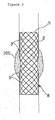
- the net body 5 of the stent 8 serves to expand the stenosed part 200 with the elastic expansion force thereof, thereby widening the tract or cavity of a bodily organ.
- the stent thus installed is kept in place by the contact force acting between itself and the stenosed part of the bodily organ.
- the stent may be slidingly moved out of the original place over time by various kinds of causes. That is to say, there is a problem in that the stent is displaced from the stenosed part.
- connection-type stent 9 includes a plurality of cylindrical net segments 8 arranged in an end-to-end relationship with one another and a unitary film 7 for covering the net segments 8 to interconnect them, the unitary film 7 being made of polytetrafluoroethylene (PTFE) or silicon.
- PTFE polytetrafluoroethylene
- connection-type stent 9 the respective net segments 8 serve to expand a stenosed part in different positions with the elastic expansion force thereof, thereby widening the tract or cavity of a bodily organ.
- the connection-type stent 9 is fixed to the stenosed part in a wavily deformed state with an increased contact force. This helps prevent the stent 9 from being displaced out of the stenosed part during its use.
- connection-type stent 9 the film 7 may be gradually dissolved over time by a secreting fluid or a bodily fluid flowing through or existing in a bile duct or other bodily organs.
- the net segments 8 are separated away from one another and sometimes displaced out of the stenosed part.
- the net segments 8 thus separated may hinder the flow of the bodily fluid or may move to other places, causing disorders to other organs. In this case, a surgical operation needs to be performed in order to remove the net segments 8.
- a stent including a cylindrical net body and an engaging protrusion formed on the outer circumferential surface of the net body for engagement with the inner wall surface of an organ.
- the engaging protrusion is formed to protrude radially outwards by interlacing an independent wire.
- a wavily deformable stent comprising a hollow cylindrical net body formed of elastically deformable wires interlaced with each other, wherein the net body extends in a longitudinal direction and terminates at open opposite ends, wherein the net body includes at least one high-rigidity section and at least one low-rigidity section less rigid than the high-rigidity section, and wherein the or each high-rigidity section and the or each low-rigidity section are arranged continuously and alternately along the longitudinal direction; the low- and high-rigidity sections being formed of crossed and bent interlaced wires, the wires in the high-rigidity section being interlaced at a first, narrow interval and the wires in the low-rigidity section being interlaced at a second, broader interval.
- the stent of the present invention may further include a resin film layer for covering one of the inner and outer circumferential surfaces of the net body, the film being made of polytetrafluoroethylene or silicon.
- the stent of the present invention may further include a pair of enlarged extension portions provided at the opposite ends of the net body, the enlarged extension portions being greater in diameter than the net body.
- a method for producing a wavily deformable stent comprising the steps of: preparing elastically deformable wires; and interlacing the wires with each other by crossing and bending to form a hollow cylindrical net body having at least one high-rigidity section and at least one low-rigidity section less rigid than the high-rigidity section, wherein the net body extends in a longitudinal direction and terminates at open opposite ends and wherein the or each high-rigidity section and the or each low-rigidity section are arranged continuously and alternately along the longitudinal direction; wherein the at least one high-rigidity section is formed by crossing and bending the interlaced wires at a first, narrow interval; and the at least one low-rigidity section is formed by crossing and bending the interlaced wires at a second, broader interval.
- the alternating high-rigidity and low-rigidity sections of the cylindrical net body can expand the stenosed part of a bodily organ with different forces and therefore can be situated inside the stenosed part in a wavily deformed state along the length of the stenosed part. This assists in increasing the contact force acting between the stenosed part and the stent, thereby preventing the stent from being displaced out of the stenosed part.
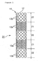
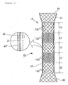
- a wavily deformable stent 20 includes a hollow cylindrical net body 15 formed of elastically deformable wires 12 interlaced with each other.
- the wires 12 are made of, e.g., ultra elastic shape-memory alloy or stainless steel.
- the net body 15 extends in a longitudinal direction and terminates at open opposite ends.
- the net body 15 includes two high-rigidity sections 21 and three low-rigidity sections 22 less rigid than the high-rigidity section 21.
- the high-rigidity sections 21 and the low-rigidity sections 22 are arranged continuously and alternately along the longitudinal direction.
- the high-rigidity sections 21 and the low-rigidity sections 22 are formed in plural numbers in the illustrated embodiment, the present invention is not limited thereto.
- the number of the high-rigidity sections 21 and the low-rigidity sections 22 may be greater or lesser than illustrated.
- the wires 12 are interlaced at a narrow interval so that each of the high-rigidity sections 21 can have a plurality of first rhombic meshes 13a with a relatively small average size.
- the high-rigidity sections 21 are formed of the wires 12 interlaced at an increased density. Therefore, the high-rigidity sections 21 show relatively high rigidity.
- the wires 12 are interlaced at a broad interval so that each of the low-rigidity sections 22 can have a plurality of second rhombic meshes 13b greater in average size and smaller in number than the first meshes 13a of the high-rigidity sections 21.
- the low-rigidity sections 22 are formed of the wires 12 interlaced at a reduced density. Therefore, the low-rigidity sections 22 show rigidity smaller than that of the high-rigidity sections 21. This means that the high-rigidity sections 21 are less pliable than the low-rigidity sections 22 and therefore can support the stenosed part of a bodily organ with a greater expanding force.
- each of the high-rigidity sections 21 is shorter than each of the low-rigidity sections 22.
- the high-rigidity sections 21 and the low-rigidity sections 22 may differ in length from each other.
- the length of the high-rigidity sections 21 and the low-rigidity sections 22 may vary with the size of the stenosed part, the shape of the stenosed part, the kinds of the bodily organ and so forth.
- the difference in rigidity between the high-rigidity sections 21 and the low-rigidity sections 22 may be set in many different ways depending on the characteristics of the stenosed part.
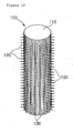
- the net body 15 of the stent 20 can be produced through the use of a jig 100 shown in Fig. 12 .
- the jig 100 includes a cylinder 110 and a plurality of pins 120 protruding radially outwards from the circumferential surface of the cylinder 100.
- the cylinder 100 has a plurality of longitudinal wire-insertion grooves 130 formed on the circumferential surface thereof at an equal spacing.
- the pins 120 are removably fixed at the intersecting points of longitudinal dividing lines and circumferential dividing lines, both of which are drawn on the circumferential surface of the cylinder 100 at an equal interval.
- the wires 12 are crossed and bent at a narrow interval through every neighboring row of the pins 120 to leave the first rhombic meshes 13a of small size between the crossed wires 12.
- the wires 12 are crossed and bent at a wide interval through every other row of the pins 120 to leave the second rhombic meshes 13b of large size between the crossed wires 12.
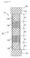
- a wavily deformable stent 50 in accordance with another embodiment of the present invention.
- the stent 50 of this embodiment is structurally the same as the stent 20 of the preceding embodiment, except that a resin film layer 40 is formed on the net body 15.
- the same component parts will be designated by like reference characters and will be omitted from description.
- the resin film layer 40 is made of, e.g., polytetrafluoroethylene (PTFE) and silicon.
- the resin film layer 40 may be divided into a first resin film layer formed on the inner circumferential surface of the net body 15 and a second resin film layer formed on the outer circumferential surface of the net body 15.
- the first resin film layer and the second resin film layer are made of different resins.
- the first resin film layer is made of polytetrafluoroethylene
- the second resin film layer will be made of silicon.
- the first resin film layer is made of silicon
- the second resin film layer will be made of polytetrafluoroethylene.
- the resin film layer 40 thus formed serves mainly to prevent the stenosed part of the bodily organ from growing into the stent 50 through the meshes 13a and 13b of the net body 15.
- the first and second resin film layers made of different resins are formed on the inner and outer circumferential surfaces of the net body 15 as set forth above, it is possible to enhance the resistance of the resin film layers to the bodily fluid, thereby allowing the stent 50 to perform its function for a prolonged period of time.
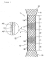
- a wavily deformable stent 31 or 60 in accordance with a further embodiment of the present invention.
- the stent 31 or 60 of this embodiment is structurally the same as the stent 20 or 50 of the preceding embodiment, except that a pair of enlarged extension portions 30 is provided at the opposite ends of the net body 15.
- the same component parts will be designated by like reference characters and will be omitted from description.
- the stent 31 shown in Fig. 7 includes a pair of enlarged extension portions 31 provided at the opposite ends of the net body 15.
- Each of the enlarged extension portions 33 is tapered such that the diameter thereof become gradually larger away from the end of the net body 15.
- the enlarged extension portions 33 serve to assure smooth flow of the bodily fluid and to increase the fixing force of the stent 31.
- each of the enlarged extension portions 32 is of a sleeve shape and has a diameter greater than that of the net body 15.
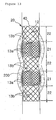
- the stent 60 shown in Fig. 9 includes a pair of enlarged extension portions 31 provided at the opposite ends of the net body 15 and a resin film layer 40 formed on the net body 15 and enlarged extension portions 31.
- Each of the enlarged extension portions 31 has a tapering shape.
- the resin film layer 40 is made of, e.g., polytetrafluoroethylene (PTFE) and silicon.
- the resin film layer 40 may be divided into a first resin film layer 40' formed on the inner circumferential surface of the net body 15 and the enlarged extension portions 31 and a second resin film layer 40" formed on the outer circumferential surface of the net body 15 and the enlarged extension portions 31.
- the first resin film layer 40' and the second resin film layer 40'' are made of different resins. More specifically, the first resin film layer 40' is made of silicon and the second resin film layer 40" is made of polytetrafluoroethylene. In case of the stent 60 shown in Fig. 11 , the first resin film layer 40' is made of polytetrafluoroethylene and the second resin film layer 40" is made of silicon.
- the first and second resin film layers 40' and 40" thus formed serve mainly to prevent the stenosed part of the bodily organ from growing into the stent 60 through the meshes 13a and 13b of the net body 15. If the first and second resin film layers 40' and 40" are made of different resins as in Figs. 10 and 11 , it is possible to enhance the resistance of the resin film layers 40' and 40'to the bodily fluid, thereby allowing the stent 60 to perform its function for a prolonged period of time.
- the stent 20 is situated inside the stenosed part of a bile duct or other bodily organs to expand the same radially outwards. It is preferred that the stent 20 used for this purpose has a length equal to or a little greater than the length of the stenosed part.
- the net body 15 of the stent 20 includes the high-rigidity sections 21 and the low-rigidity sections 22 as set forth above, the stent 20 is deformed into a wavelike form when situated inside the stenosed part.
- the high-rigidity sections 21 expand the stenosed part with a greater expansion force but the low-rigidity sections 22 expand the stenosed part with an expansion force smaller than that of the high-rigidity sections 21.
Landscapes
- Health & Medical Sciences (AREA)
- Engineering & Computer Science (AREA)
- Biomedical Technology (AREA)
- General Health & Medical Sciences (AREA)
- Veterinary Medicine (AREA)
- Transplantation (AREA)
- Oral & Maxillofacial Surgery (AREA)
- Public Health (AREA)
- Life Sciences & Earth Sciences (AREA)
- Animal Behavior & Ethology (AREA)
- Cardiology (AREA)
- Vascular Medicine (AREA)
- Heart & Thoracic Surgery (AREA)
- Chemical & Material Sciences (AREA)
- Inorganic Chemistry (AREA)
- Dermatology (AREA)
- Medicinal Chemistry (AREA)
- Epidemiology (AREA)
- Prostheses (AREA)
- Media Introduction/Drainage Providing Device (AREA)
Claims (13)
- Wellenförmig verformbarer Stent, umfassend einen hohlen zylinderförmigen Netzkörper (15), der aus elastisch verformbaren Drähten (12), die miteinander verflochten sind, ausgebildet ist, wobei der Netzkörper (15) sich in einer Längsrichtung erstreckt und in gegenüberliegenden offenen Enden endet, wobei der Netzkörper (15) mindestens einen Bereich hoher Steifigkeit (21) und mindestens einen Bereich niedriger Steifigkeit (22), der weniger starr ist als der Bereich hoher Steifigkeit (21), aufweist, dadurch gekennzeichnet, dass:der oder jeder Bereich hoher Steifigkeit (21) und der oder jeder Bereich niedriger Steifigkeit (22) kontinuierlich und abwechselnd entlang der Längsrichtung angeordnet sind;der mindestens eine Bereich hoher Steifigkeit (21) aus gekreuzt und gebogen verflochtenen Drähten (12) ausgebildet ist, wobei die Drähte (12) mit einem ersten schmalen Zwischenraum verflochten sind; undder mindestens eine Bereich niedriger Steifigkeit (22) auch aus gekreuzt und gebogen verflochtenen Drähten (12) ausgebildet ist, wobei die Drähte (12) mit einem zweiten breiteren Zwischenraum verflochten sind.
- Stent nach Anspruch 1, wobei der Bereich hoher Steifigkeit (21) eine Vielzahl erster Maschen (13a) aufweist und der Bereich niedriger Steifigkeit (22) eine Vielzahl zweiter Maschen (13b) aufweist, die in der Durchschnittsgröße größer und in der Anzahl geringer als die ersten Maschen (13a) sind.
- Stent nach Anspruch 1 oder 2, wobei der Bereich hoher Steifigkeit (21) und der Bereich niedriger Steifigkeit (22) sich in der Länge voneinander unterscheiden.
- Stent nach einem der vorhergehenden Ansprüche, ferner umfassend ein Paar von vergrößerten Verlängerungsabschnitten (30), die an den entgegengesetzten Enden des Netzkörpers (15) vorgesehen sind, wobei die vergrößerten Verlängerungsabschnitte (30) im Durchmesser größer sind als der Netzkörper (15).
- Stent nach einem der vorhergehenden Ansprüche, ferner umfassend eine Harzfilmschicht (40), die auf dem Netzkörper (15) und, falls vorhanden, auf den vergrößerten Verlängerungsabschnitten (30) ausgebildet ist.
- Stent nach Anspruch 5, wobei die Harzfilmschicht (40) aus einer Substanz hergestellt ist, die ausgewählt ist aus der Gruppe bestehend aus Polytetrafluorethylen und Silikon.
- Stent nach einem der Ansprüche 1 bis 4, wobei der Netzkörper (15) eine innere Umfangsfläche und eine äußere Umfangsfläche aufweist und ferner eine erste Harzfilmschicht (40), die auf der inneren Umfangsfläche des Netzkörpers ausgebildet ist, und eine zweite Harzfilmschicht (40") aufweist, die auf der äußeren Umfangsfläche des Netzkörpers (15) ausgebildet ist.
- Stent nach Anspruch 7, wobei die erste Harzfilmschicht (40) und die zweite Harzfilmschicht (40") aus unterschiedlichen Harzen hergestellt sind.
- Stent nach einem der vorhergehenden Ansprüche und mit zwei Bereichen hoher Steifigkeit (21) und drei Bereichen niedriger Steifigkeit (22).
- Verfahren zur Herstellung eines wellenförmig verformbaren Stents, umfassend die Schritte:- Vorbereiten elastisch verformbarer Drähte (12);
und- Verflechten der Drähte (12) miteinander durch Kreuzen und Biegen, um einen hohlen zylinderförmigen Netzkörper (15) auszubilden, der mindestens einen Bereich hoher Steifigkeit (21) und mindestens einen Bereich niedriger Steifigkeit (22) aufweist, der weniger starr ist als der Bereich hoher Steifigkeit (21), wobei der Netzkörper sich in einer Längsrichtung erstreckt und in offenen gegenüberliegenden Enden endet und wobei der oder jeder Bereich hoher Steifigkeit (21) und der oder jeder Bereich niedriger Steifigkeit (22) kontinuierlich und abwechselnd entlang der Längsrichtung angeordnet sind;wobei der mindestens eine Bereich hoher Steifigkeit (21) durch Kreuzen und Biegen der verflochtenen Drähte (12) mit einem ersten schmalen Zwischenraum gebildet wird; und
der mindestens eine Bereich niedriger Steifigkeit (22) durch Kreuzen und Biegen der verflochtenen Drähte (12) mit einem zweiten breiteren Zwischenraum gebildet wird. - Verfahren nach Anspruch 10, ferner umfassend den Schritt: Bereitstellen eines Paares vergrößerter Verlängerungsabschnitte (30) an den entgegengesetzten Enden des Netzkörpers (15), wobei die vergrößerten Verlängerungsabschnitte (30) im Durchmesser größer sind als der Netzkörper (15).
- Verfahren nach Anspruch 10 oder 11, ferner umfassend den Schritt: Ausbilden einer Harzfilmschicht (40) auf dem Netzkörper (15).
- Verfahren nach einem der Ansprüche 10 bis 12, wobei die Drähte (12) durch Kreuzen und Biegen an Stiften (120) einer Montagevorrichtung (100) verflochten werden.
Applications Claiming Priority (1)
| Application Number | Priority Date | Filing Date | Title |
|---|---|---|---|
| KR20080101638A KR20100042478A (ko) | 2008-10-16 | 2008-10-16 | 굴곡 변형성을 갖는 스텐트의 제조방법과 그 스텐트 |
Publications (3)
| Publication Number | Publication Date |
|---|---|
| EP2177181A1 EP2177181A1 (de) | 2010-04-21 |
| EP2177181B1 true EP2177181B1 (de) | 2015-06-17 |
| EP2177181B8 EP2177181B8 (de) | 2015-07-22 |
Family
ID=41466666
Family Applications (1)
| Application Number | Title | Priority Date | Filing Date |
|---|---|---|---|
| EP09275090.0A Active EP2177181B8 (de) | 2008-10-16 | 2009-10-05 | Wellenförmig verformbarer Stent und Verfahren zu dessen Herstellung |
Country Status (6)
| Country | Link |
|---|---|
| US (1) | US20100256732A1 (de) |
| EP (1) | EP2177181B8 (de) |
| JP (1) | JP2010094510A (de) |
| KR (1) | KR20100042478A (de) |
| CN (1) | CN101721267A (de) |
| AU (1) | AU2009217462B2 (de) |
Cited By (3)
| Publication number | Priority date | Publication date | Assignee | Title |
|---|---|---|---|---|
| US11419741B2 (en) | 2019-06-17 | 2022-08-23 | Boston Scientific Scimed, Inc. | Covered endoprosthesis with improved branch access |
| US11564787B2 (en) | 2019-11-18 | 2023-01-31 | Boston Scientific Scimed, Inc. | Stent with improved anti-migration properties |
| US11678970B2 (en) | 2018-12-04 | 2023-06-20 | Boston Scientific Scimed, Inc. | Device for anastomotic bypass |
Families Citing this family (33)
| Publication number | Priority date | Publication date | Assignee | Title |
|---|---|---|---|---|
| SG175723A1 (en) | 2004-05-25 | 2011-12-29 | Tyco Healthcare | Vascular stenting for aneurysms |
| WO2005115118A2 (en) | 2004-05-25 | 2005-12-08 | Chestnut Medical Technologies, Inc. | Flexible vascular occluding device |
| US8623067B2 (en) | 2004-05-25 | 2014-01-07 | Covidien Lp | Methods and apparatus for luminal stenting |
| WO2007100556A1 (en) | 2006-02-22 | 2007-09-07 | Ev3 Inc. | Embolic protection systems having radiopaque filter mesh |
| CN101897630A (zh) * | 2010-08-16 | 2010-12-01 | 南京微创医学科技有限公司 | 可弯曲顺应型管腔内支架 |
| KR101330825B1 (ko) | 2011-01-14 | 2013-11-15 | 신경민 | 굽힘 특성이 양호한 스텐트의 제조방법과 그 스텐트 |
| EP2684545B1 (de) * | 2011-03-08 | 2016-10-05 | Piolax Medical Devices, Inc. | Stent |
| US20140114343A1 (en) * | 2011-05-26 | 2014-04-24 | The Asan Foundation | Stent for the coil embolization of a cerebral aneurysm |
| DE102011102939B4 (de) * | 2011-05-31 | 2013-07-04 | Acandis Gmbh & Co. Kg | Medizinische Vorrichtung zur Einfuhr in ein Hohlorgan |
| KR101320480B1 (ko) * | 2012-03-19 | 2013-10-23 | 주식회사 엠아이텍 | 플렉서블 스텐트 |
| US9114001B2 (en) | 2012-10-30 | 2015-08-25 | Covidien Lp | Systems for attaining a predetermined porosity of a vascular device |
| US9452070B2 (en) * | 2012-10-31 | 2016-09-27 | Covidien Lp | Methods and systems for increasing a density of a region of a vascular device |
| US9943427B2 (en) | 2012-11-06 | 2018-04-17 | Covidien Lp | Shaped occluding devices and methods of using the same |
| US9157174B2 (en) | 2013-02-05 | 2015-10-13 | Covidien Lp | Vascular device for aneurysm treatment and providing blood flow into a perforator vessel |
| CN104507422B (zh) * | 2013-03-07 | 2016-08-24 | 奥林巴斯株式会社 | 医疗用支架 |
| KR101498584B1 (ko) * | 2013-05-15 | 2015-03-04 | 주식회사 스텐다드싸이텍 | 이동방지용 스텐트 |
| KR101645628B1 (ko) * | 2013-11-08 | 2016-08-08 | 주식회사 비씨엠 | 전기 열 치료용 스텐트 |
| KR101557010B1 (ko) * | 2014-07-11 | 2015-10-02 | 주식회사 비씨엠 | 커버드 스텐트와 그 제조방법 |
| DE102014115337A1 (de) * | 2014-10-21 | 2016-04-21 | Nasib Dlaikan-Campos | Stent zum Schienen einer Vene und System zum Setzen eines Stents |
| KR101657648B1 (ko) * | 2014-10-21 | 2016-09-19 | (주) 태웅메디칼 | 미끄럼 방지용 스텐트 제조 방법 및 그에 의해 제조된 미끄럼 방지 스텐트 |
| KR101651148B1 (ko) * | 2014-10-31 | 2016-09-05 | 주식회사 엠아이텍 | 내시경 안내용 스텐트 |
| KR101772482B1 (ko) * | 2015-07-27 | 2017-08-29 | (주) 태웅메디칼 | 미끄럼 방지 기능이 향상된 스텐트 |
| GB201718299D0 (en) | 2017-11-03 | 2017-12-20 | Ab Wasstand Dev | Stents |
| KR102133818B1 (ko) * | 2018-04-12 | 2020-07-14 | (주)태웅메디칼 | 미끄럼 방지용 스텐트 |
| US11083610B2 (en) * | 2019-01-08 | 2021-08-10 | Covidien Lp | Expandable stent delivery apparatus to cover an access site |
| KR102196226B1 (ko) * | 2019-01-28 | 2020-12-29 | 이재희 | 스텐트 및 그 제작 방법 |
| CN109771097A (zh) * | 2019-03-11 | 2019-05-21 | 北京航空航天大学 | 具有径向支撑力变化的人工介入型主动脉瓣膜支架 |
| WO2020222363A1 (ko) * | 2019-04-29 | 2020-11-05 | 주식회사 에스앤지바이오텍 | 스텐트 |
| KR102235960B1 (ko) * | 2019-05-30 | 2021-04-02 | 박성욱 | 길이 조절 가능한 내강용 스텐트 |
| JP2021129982A (ja) * | 2020-02-19 | 2021-09-09 | 川澄化学工業株式会社 | ステント |
| KR102757606B1 (ko) * | 2020-07-20 | 2025-01-21 | 주식회사 에스앤지바이오텍 | 스텐트 |
| EP4445869A4 (de) * | 2021-12-10 | 2025-11-12 | Shenzhen Lifetech Respiration Scient Co Ltd | Stent für die atemwege |
| CN115889619A (zh) * | 2022-10-27 | 2023-04-04 | 常州乐奥医疗科技股份有限公司 | 一种胆道支架制造夹具及胆道支架制造方法 |
Family Cites Families (14)
| Publication number | Priority date | Publication date | Assignee | Title |
|---|---|---|---|---|
| US5064435A (en) * | 1990-06-28 | 1991-11-12 | Schneider (Usa) Inc. | Self-expanding prosthesis having stable axial length |
| JP3583801B2 (ja) * | 1993-03-03 | 2004-11-04 | ボストン サイエンティフィック リミテッド | 管腔用のステントおよび移植体 |
| RU2089131C1 (ru) * | 1993-12-28 | 1997-09-10 | Сергей Апполонович Пульнев | Стент |
| CA2189006A1 (en) * | 1994-04-29 | 1995-11-09 | Boston Scientific Corporation | Medical prosthetic stent and method of manufacture |
| US5575818A (en) * | 1995-02-14 | 1996-11-19 | Corvita Corporation | Endovascular stent with locking ring |
| ATE218052T1 (de) * | 1995-11-27 | 2002-06-15 | Schneider Europ Gmbh | Stent zur anwendung in einem körperlichen durchgang |
| US6585758B1 (en) * | 1999-11-16 | 2003-07-01 | Scimed Life Systems, Inc. | Multi-section filamentary endoluminal stent |
| KR100457630B1 (ko) * | 2001-04-04 | 2004-11-18 | (주) 태웅메디칼 | 형상기억합금을 이용한 가변상태 유지형 확장기구의제조방법과 이에 의해 제조된 확장기구 |
| JP4608672B2 (ja) * | 2001-09-17 | 2011-01-12 | Junken Medical株式会社 | ステント付きグラフト |
| US20030135265A1 (en) * | 2002-01-04 | 2003-07-17 | Stinson Jonathan S. | Prostheses implantable in enteral vessels |
| JP2005278993A (ja) * | 2004-03-30 | 2005-10-13 | Terumo Corp | 生体内留置用ステントおよびその製造方法 |
| US20070179590A1 (en) * | 2005-12-29 | 2007-08-02 | Wenfeng Lu | Hybrid intraluminal device with varying expansion force |
| WO2008088537A2 (en) * | 2006-12-20 | 2008-07-24 | Boston Scientific Limited | Stent with a coating for delivering a therapeutic agent |
| DE102007053070B4 (de) * | 2007-11-07 | 2011-08-25 | Acandis GmbH & Co. KG, 76327 | Medizinisches Implantat und Verfahren zur Herstellung eines derartigen Implantats |
-
2008
- 2008-10-16 KR KR20080101638A patent/KR20100042478A/ko not_active Ceased
-
2009
- 2009-09-23 AU AU2009217462A patent/AU2009217462B2/en not_active Ceased
- 2009-10-05 EP EP09275090.0A patent/EP2177181B8/de active Active
- 2009-10-08 JP JP2009234596A patent/JP2010094510A/ja active Pending
- 2009-10-13 US US12/577,871 patent/US20100256732A1/en not_active Abandoned
- 2009-10-14 CN CN200910177883A patent/CN101721267A/zh active Pending
Cited By (5)
| Publication number | Priority date | Publication date | Assignee | Title |
|---|---|---|---|---|
| US11678970B2 (en) | 2018-12-04 | 2023-06-20 | Boston Scientific Scimed, Inc. | Device for anastomotic bypass |
| US12551328B2 (en) | 2018-12-04 | 2026-02-17 | Boston Scientific Scimed, Inc. | Device for anastomotic bypass |
| US11419741B2 (en) | 2019-06-17 | 2022-08-23 | Boston Scientific Scimed, Inc. | Covered endoprosthesis with improved branch access |
| US11564787B2 (en) | 2019-11-18 | 2023-01-31 | Boston Scientific Scimed, Inc. | Stent with improved anti-migration properties |
| US12268589B2 (en) | 2019-11-18 | 2025-04-08 | Boston Scientific Scimed, Inc. | Stent with improved anti-migration properties |
Also Published As
| Publication number | Publication date |
|---|---|
| KR20100042478A (ko) | 2010-04-26 |
| AU2009217462A1 (en) | 2010-05-06 |
| AU2009217462B2 (en) | 2011-02-10 |
| CN101721267A (zh) | 2010-06-09 |
| EP2177181B8 (de) | 2015-07-22 |
| EP2177181A1 (de) | 2010-04-21 |
| JP2010094510A (ja) | 2010-04-30 |
| US20100256732A1 (en) | 2010-10-07 |
Similar Documents
| Publication | Publication Date | Title |
|---|---|---|
| EP2177181B1 (de) | Wellenförmig verformbarer Stent und Verfahren zu dessen Herstellung | |
| EP3254643B1 (de) | Verbindungsstent und herstellungsverfahren dafür | |
| US20230277294A1 (en) | Device for anastomotic bypass | |
| US6203569B1 (en) | Flexible stent | |
| CN1183978C (zh) | 可膨胀扩张器 | |
| US5707387A (en) | Flexible stent | |
| JP5575327B2 (ja) | ステント | |
| KR20120018772A (ko) | 플렉서블 장치 | |
| KR20170084214A (ko) | 스텐트 보철 | |
| JP7324267B2 (ja) | 非外傷性スペーサを備えたステント | |
| US11963893B2 (en) | Esophageal stents with helical thread | |
| EP1207930A1 (de) | Vorrichtung zur verabreichung von medikamenten mit reduziertem profil | |
| JP6470219B2 (ja) | ステントおよび医療機器 | |
| JP2011504407A (ja) | 円筒形ステント | |
| KR100267019B1 (ko) | 내강 확장용 스텐트 및 그 제조방법 | |
| JP4835113B2 (ja) | ステント | |
| US20250127639A1 (en) | Woven braid pattern for stents and related methods | |
| CN116211562B (zh) | 一种凸点支架 | |
| WO2019087433A1 (ja) | ステントおよび医療機器 | |
| JP2004267492A (ja) | 血管径保持性の優れた柔軟なステント | |
| AU2024288428A1 (en) | Multi-directional hinging stent with one or more funnel shaped connectors | |
| JP2023118339A (ja) | ステント | |
| EP4669401A1 (de) | Mehrdraht-kathetergeflecht mit veränderlichem webmuster |
Legal Events
| Date | Code | Title | Description |
|---|---|---|---|
| PUAI | Public reference made under article 153(3) epc to a published international application that has entered the european phase |
Free format text: ORIGINAL CODE: 0009012 |
|
| 17P | Request for examination filed |
Effective date: 20091012 |
|
| AK | Designated contracting states |
Kind code of ref document: A1 Designated state(s): AT BE BG CH CY CZ DE DK EE ES FI FR GB GR HR HU IE IS IT LI LT LU LV MC MK MT NL NO PL PT RO SE SI SK SM TR |
|
| 17Q | First examination report despatched |
Effective date: 20100811 |
|
| GRAP | Despatch of communication of intention to grant a patent |
Free format text: ORIGINAL CODE: EPIDOSNIGR1 |
|
| INTG | Intention to grant announced |
Effective date: 20150109 |
|
| GRAS | Grant fee paid |
Free format text: ORIGINAL CODE: EPIDOSNIGR3 |
|
| GRAA | (expected) grant |
Free format text: ORIGINAL CODE: 0009210 |
|
| AK | Designated contracting states |
Kind code of ref document: B1 Designated state(s): AT BE BG CH CY CZ DE DK EE ES FI FR GB GR HR HU IE IS IT LI LT LU LV MC MK MT NL NO PL PT RO SE SI SK SM TR |
|
| REG | Reference to a national code |
Ref country code: GB Ref legal event code: FG4D |
|
| REG | Reference to a national code |
Ref country code: CH Ref legal event code: EP |
|
| RIN2 | Information on inventor provided after grant (corrected) |
Inventor name: SHIN, KYONG-MIN Inventor name: MYUNG, BYUNG-CHEOL |
|
| RAP2 | Party data changed (patent owner data changed or rights of a patent transferred) |
Owner name: TAEWOONG MEDICAL CO., LTD. Owner name: SHIN, KYONG-MIN |
|
| REG | Reference to a national code |
Ref country code: AT Ref legal event code: REF Ref document number: 731475 Country of ref document: AT Kind code of ref document: T Effective date: 20150715 |
|
| RIN2 | Information on inventor provided after grant (corrected) |
Inventor name: SHIN, KYONG-MIN Inventor name: MYUNG, BYUNG-CHEOL |
|
| REG | Reference to a national code |
Ref country code: IE Ref legal event code: FG4D |
|
| REG | Reference to a national code |
Ref country code: DE Ref legal event code: R096 Ref document number: 602009031729 Country of ref document: DE |
|
| PG25 | Lapsed in a contracting state [announced via postgrant information from national office to epo] |
Ref country code: NO Free format text: LAPSE BECAUSE OF FAILURE TO SUBMIT A TRANSLATION OF THE DESCRIPTION OR TO PAY THE FEE WITHIN THE PRESCRIBED TIME-LIMIT Effective date: 20150917 Ref country code: HR Free format text: LAPSE BECAUSE OF FAILURE TO SUBMIT A TRANSLATION OF THE DESCRIPTION OR TO PAY THE FEE WITHIN THE PRESCRIBED TIME-LIMIT Effective date: 20150617 Ref country code: FI Free format text: LAPSE BECAUSE OF FAILURE TO SUBMIT A TRANSLATION OF THE DESCRIPTION OR TO PAY THE FEE WITHIN THE PRESCRIBED TIME-LIMIT Effective date: 20150617 Ref country code: LT Free format text: LAPSE BECAUSE OF FAILURE TO SUBMIT A TRANSLATION OF THE DESCRIPTION OR TO PAY THE FEE WITHIN THE PRESCRIBED TIME-LIMIT Effective date: 20150617 |
|
| REG | Reference to a national code |
Ref country code: AT Ref legal event code: MK05 Ref document number: 731475 Country of ref document: AT Kind code of ref document: T Effective date: 20150617 |
|
| REG | Reference to a national code |
Ref country code: LT Ref legal event code: MG4D Ref country code: NL Ref legal event code: MP Effective date: 20150617 |
|
| PG25 | Lapsed in a contracting state [announced via postgrant information from national office to epo] |
Ref country code: GR Free format text: LAPSE BECAUSE OF FAILURE TO SUBMIT A TRANSLATION OF THE DESCRIPTION OR TO PAY THE FEE WITHIN THE PRESCRIBED TIME-LIMIT Effective date: 20150918 Ref country code: LV Free format text: LAPSE BECAUSE OF FAILURE TO SUBMIT A TRANSLATION OF THE DESCRIPTION OR TO PAY THE FEE WITHIN THE PRESCRIBED TIME-LIMIT Effective date: 20150617 Ref country code: BG Free format text: LAPSE BECAUSE OF FAILURE TO SUBMIT A TRANSLATION OF THE DESCRIPTION OR TO PAY THE FEE WITHIN THE PRESCRIBED TIME-LIMIT Effective date: 20150917 |
|
| PG25 | Lapsed in a contracting state [announced via postgrant information from national office to epo] |
Ref country code: EE Free format text: LAPSE BECAUSE OF FAILURE TO SUBMIT A TRANSLATION OF THE DESCRIPTION OR TO PAY THE FEE WITHIN THE PRESCRIBED TIME-LIMIT Effective date: 20150617 |
|
| PG25 | Lapsed in a contracting state [announced via postgrant information from national office to epo] |
Ref country code: PT Free format text: LAPSE BECAUSE OF FAILURE TO SUBMIT A TRANSLATION OF THE DESCRIPTION OR TO PAY THE FEE WITHIN THE PRESCRIBED TIME-LIMIT Effective date: 20151019 Ref country code: IS Free format text: LAPSE BECAUSE OF FAILURE TO SUBMIT A TRANSLATION OF THE DESCRIPTION OR TO PAY THE FEE WITHIN THE PRESCRIBED TIME-LIMIT Effective date: 20151017 Ref country code: RO Free format text: LAPSE BECAUSE OF NON-PAYMENT OF DUE FEES Effective date: 20150617 Ref country code: CZ Free format text: LAPSE BECAUSE OF FAILURE TO SUBMIT A TRANSLATION OF THE DESCRIPTION OR TO PAY THE FEE WITHIN THE PRESCRIBED TIME-LIMIT Effective date: 20150617 Ref country code: SK Free format text: LAPSE BECAUSE OF FAILURE TO SUBMIT A TRANSLATION OF THE DESCRIPTION OR TO PAY THE FEE WITHIN THE PRESCRIBED TIME-LIMIT Effective date: 20150617 Ref country code: AT Free format text: LAPSE BECAUSE OF FAILURE TO SUBMIT A TRANSLATION OF THE DESCRIPTION OR TO PAY THE FEE WITHIN THE PRESCRIBED TIME-LIMIT Effective date: 20150617 Ref country code: ES Free format text: LAPSE BECAUSE OF FAILURE TO SUBMIT A TRANSLATION OF THE DESCRIPTION OR TO PAY THE FEE WITHIN THE PRESCRIBED TIME-LIMIT Effective date: 20150617 Ref country code: PL Free format text: LAPSE BECAUSE OF FAILURE TO SUBMIT A TRANSLATION OF THE DESCRIPTION OR TO PAY THE FEE WITHIN THE PRESCRIBED TIME-LIMIT Effective date: 20150617 |
|
| REG | Reference to a national code |
Ref country code: DE Ref legal event code: R097 Ref document number: 602009031729 Country of ref document: DE |
|
| PLBE | No opposition filed within time limit |
Free format text: ORIGINAL CODE: 0009261 |
|
| STAA | Information on the status of an ep patent application or granted ep patent |
Free format text: STATUS: NO OPPOSITION FILED WITHIN TIME LIMIT |
|
| PG25 | Lapsed in a contracting state [announced via postgrant information from national office to epo] |
Ref country code: DK Free format text: LAPSE BECAUSE OF FAILURE TO SUBMIT A TRANSLATION OF THE DESCRIPTION OR TO PAY THE FEE WITHIN THE PRESCRIBED TIME-LIMIT Effective date: 20150617 Ref country code: IT Free format text: LAPSE BECAUSE OF FAILURE TO SUBMIT A TRANSLATION OF THE DESCRIPTION OR TO PAY THE FEE WITHIN THE PRESCRIBED TIME-LIMIT Effective date: 20150617 |
|
| 26N | No opposition filed |
Effective date: 20160318 |
|
| PG25 | Lapsed in a contracting state [announced via postgrant information from national office to epo] |
Ref country code: LU Free format text: LAPSE BECAUSE OF FAILURE TO SUBMIT A TRANSLATION OF THE DESCRIPTION OR TO PAY THE FEE WITHIN THE PRESCRIBED TIME-LIMIT Effective date: 20151005 |
|
| REG | Reference to a national code |
Ref country code: CH Ref legal event code: PL |
|
| GBPC | Gb: european patent ceased through non-payment of renewal fee |
Effective date: 20151005 |
|
| PG25 | Lapsed in a contracting state [announced via postgrant information from national office to epo] |
Ref country code: MC Free format text: LAPSE BECAUSE OF FAILURE TO SUBMIT A TRANSLATION OF THE DESCRIPTION OR TO PAY THE FEE WITHIN THE PRESCRIBED TIME-LIMIT Effective date: 20150617 |
|
| REG | Reference to a national code |
Ref country code: IE Ref legal event code: MM4A |
|
| PG25 | Lapsed in a contracting state [announced via postgrant information from national office to epo] |
Ref country code: GB Free format text: LAPSE BECAUSE OF NON-PAYMENT OF DUE FEES Effective date: 20151005 Ref country code: CH Free format text: LAPSE BECAUSE OF NON-PAYMENT OF DUE FEES Effective date: 20151031 Ref country code: LI Free format text: LAPSE BECAUSE OF NON-PAYMENT OF DUE FEES Effective date: 20151031 |
|
| REG | Reference to a national code |
Ref country code: FR Ref legal event code: ST Effective date: 20160630 |
|
| PG25 | Lapsed in a contracting state [announced via postgrant information from national office to epo] |
Ref country code: FR Free format text: LAPSE BECAUSE OF NON-PAYMENT OF DUE FEES Effective date: 20151102 Ref country code: SI Free format text: LAPSE BECAUSE OF FAILURE TO SUBMIT A TRANSLATION OF THE DESCRIPTION OR TO PAY THE FEE WITHIN THE PRESCRIBED TIME-LIMIT Effective date: 20150617 |
|
| PG25 | Lapsed in a contracting state [announced via postgrant information from national office to epo] |
Ref country code: IE Free format text: LAPSE BECAUSE OF NON-PAYMENT OF DUE FEES Effective date: 20151005 |
|
| PG25 | Lapsed in a contracting state [announced via postgrant information from national office to epo] |
Ref country code: BE Free format text: LAPSE BECAUSE OF FAILURE TO SUBMIT A TRANSLATION OF THE DESCRIPTION OR TO PAY THE FEE WITHIN THE PRESCRIBED TIME-LIMIT Effective date: 20150617 |
|
| PG25 | Lapsed in a contracting state [announced via postgrant information from national office to epo] |
Ref country code: HU Free format text: LAPSE BECAUSE OF FAILURE TO SUBMIT A TRANSLATION OF THE DESCRIPTION OR TO PAY THE FEE WITHIN THE PRESCRIBED TIME-LIMIT; INVALID AB INITIO Effective date: 20091005 Ref country code: SM Free format text: LAPSE BECAUSE OF FAILURE TO SUBMIT A TRANSLATION OF THE DESCRIPTION OR TO PAY THE FEE WITHIN THE PRESCRIBED TIME-LIMIT Effective date: 20150617 |
|
| PG25 | Lapsed in a contracting state [announced via postgrant information from national office to epo] |
Ref country code: NL Free format text: LAPSE BECAUSE OF FAILURE TO SUBMIT A TRANSLATION OF THE DESCRIPTION OR TO PAY THE FEE WITHIN THE PRESCRIBED TIME-LIMIT Effective date: 20150617 Ref country code: CY Free format text: LAPSE BECAUSE OF FAILURE TO SUBMIT A TRANSLATION OF THE DESCRIPTION OR TO PAY THE FEE WITHIN THE PRESCRIBED TIME-LIMIT Effective date: 20150617 Ref country code: SE Free format text: LAPSE BECAUSE OF FAILURE TO SUBMIT A TRANSLATION OF THE DESCRIPTION OR TO PAY THE FEE WITHIN THE PRESCRIBED TIME-LIMIT Effective date: 20150617 |
|
| PG25 | Lapsed in a contracting state [announced via postgrant information from national office to epo] |
Ref country code: TR Free format text: LAPSE BECAUSE OF FAILURE TO SUBMIT A TRANSLATION OF THE DESCRIPTION OR TO PAY THE FEE WITHIN THE PRESCRIBED TIME-LIMIT Effective date: 20150617 Ref country code: MT Free format text: LAPSE BECAUSE OF FAILURE TO SUBMIT A TRANSLATION OF THE DESCRIPTION OR TO PAY THE FEE WITHIN THE PRESCRIBED TIME-LIMIT Effective date: 20150617 |
|
| PG25 | Lapsed in a contracting state [announced via postgrant information from national office to epo] |
Ref country code: MK Free format text: LAPSE BECAUSE OF FAILURE TO SUBMIT A TRANSLATION OF THE DESCRIPTION OR TO PAY THE FEE WITHIN THE PRESCRIBED TIME-LIMIT Effective date: 20150617 |
|
| REG | Reference to a national code |
Ref country code: DE Ref legal event code: R082 Ref document number: 602009031729 Country of ref document: DE Representative=s name: HL KEMPNER PATENTANWAELTE, SOLICITORS (ENGLAND, DE Ref country code: DE Ref legal event code: R082 Ref document number: 602009031729 Country of ref document: DE Representative=s name: HL KEMPNER PARTG MBB, DE Ref country code: DE Ref legal event code: R082 Ref document number: 602009031729 Country of ref document: DE Representative=s name: HL KEMPNER PATENTANWALT, RECHTSANWALT, SOLICIT, DE |
|
| REG | Reference to a national code |
Ref country code: DE Ref legal event code: R081 Ref document number: 602009031729 Country of ref document: DE Owner name: TAEWOONG MEDICAL CO., LTD., GIMPO-SI, KR Free format text: FORMER OWNERS: SHIN, KYONG MIN, SEOUL, KR; TAEWOONG MEDICAL CO., LTD., KIMPO, KYONGGI, KR |
|
| PGFP | Annual fee paid to national office [announced via postgrant information from national office to epo] |
Ref country code: DE Payment date: 20251020 Year of fee payment: 17 |