EP2177271A1 - Magnetisches Trennsystem mit flexiblen magnetischen Stiften - Google Patents
Magnetisches Trennsystem mit flexiblen magnetischen Stiften Download PDFInfo
- Publication number
- EP2177271A1 EP2177271A1 EP08105576A EP08105576A EP2177271A1 EP 2177271 A1 EP2177271 A1 EP 2177271A1 EP 08105576 A EP08105576 A EP 08105576A EP 08105576 A EP08105576 A EP 08105576A EP 2177271 A1 EP2177271 A1 EP 2177271A1
- Authority
- EP
- European Patent Office
- Prior art keywords
- magnetic
- separation
- plate
- pins
- magnetic separation
- Prior art date
- Legal status (The legal status is an assumption and is not a legal conclusion. Google has not performed a legal analysis and makes no representation as to the accuracy of the status listed.)
- Granted
Links
Images

Classifications
-
- B—PERFORMING OPERATIONS; TRANSPORTING
- B03—SEPARATION OF SOLID MATERIALS USING LIQUIDS OR USING PNEUMATIC TABLES OR JIGS; MAGNETIC OR ELECTROSTATIC SEPARATION OF SOLID MATERIALS FROM SOLID MATERIALS OR FLUIDS; SEPARATION BY HIGH-VOLTAGE ELECTRIC FIELDS
- B03C—MAGNETIC OR ELECTROSTATIC SEPARATION OF SOLID MATERIALS FROM SOLID MATERIALS OR FLUIDS; SEPARATION BY HIGH-VOLTAGE ELECTRIC FIELDS
- B03C1/00—Magnetic separation
- B03C1/02—Magnetic separation acting directly on the substance being separated
- B03C1/28—Magnetic plugs and dipsticks
- B03C1/288—Magnetic plugs and dipsticks disposed at the outer circumference of a recipient
-
- B—PERFORMING OPERATIONS; TRANSPORTING
- B03—SEPARATION OF SOLID MATERIALS USING LIQUIDS OR USING PNEUMATIC TABLES OR JIGS; MAGNETIC OR ELECTROSTATIC SEPARATION OF SOLID MATERIALS FROM SOLID MATERIALS OR FLUIDS; SEPARATION BY HIGH-VOLTAGE ELECTRIC FIELDS
- B03C—MAGNETIC OR ELECTROSTATIC SEPARATION OF SOLID MATERIALS FROM SOLID MATERIALS OR FLUIDS; SEPARATION BY HIGH-VOLTAGE ELECTRIC FIELDS
- B03C2201/00—Details of magnetic or electrostatic separation
- B03C2201/18—Magnetic separation whereby the particles are suspended in a liquid
-
- B—PERFORMING OPERATIONS; TRANSPORTING
- B03—SEPARATION OF SOLID MATERIALS USING LIQUIDS OR USING PNEUMATIC TABLES OR JIGS; MAGNETIC OR ELECTROSTATIC SEPARATION OF SOLID MATERIALS FROM SOLID MATERIALS OR FLUIDS; SEPARATION BY HIGH-VOLTAGE ELECTRIC FIELDS
- B03C—MAGNETIC OR ELECTROSTATIC SEPARATION OF SOLID MATERIALS FROM SOLID MATERIALS OR FLUIDS; SEPARATION BY HIGH-VOLTAGE ELECTRIC FIELDS
- B03C2201/00—Details of magnetic or electrostatic separation
- B03C2201/26—Details of magnetic or electrostatic separation for use in medical or biological applications
Definitions
- the present invention belongs to the field of analytics, particularly the separation and/or isolation of biological materials such as nucleic acids or proteins in or from complex mixtures. Within that field, the present invention relates to magnetic separation.
- Magnetic particles can, for instance, be used as a binding support for biological materials such as proteins or nucleic acids.
- the magnetic particles are contacted with a liquid sample containing an analyte in a multiwell plate, under conditions that facilitate binding of the analyte to the magnetic particles. The latter can then be subsequently separated from the liquid by means of magnetic forces generated by magnetic pins.
- US 5,779,907 discloses a device in which such magnetic pins are attached to a base plate, wherein the multiwell plate containing sample and magnetic particles is exposed to a magnetic field generated by the magnetic pins upon physical combination of the pin-bearing base plate with said multiwell plate.
- the magnetic pins are moved into close vicinity to the wells by means of being introduced into preadapted recesses in locations of the multiwell plate not containing any samples.
- the present invention provides an alternative solution displaying several advantages.
- the present invention provides a magnetic separation plate including flexible or flexibly fastened magnetic or magnetizable pins. New methods and uses comprising this plate are further provided.
- the plate can also be part of magnetic separation system further comprising a multiwell plate.
- one aspect of the invention is an analytical system for the processing and/or analysis of a sample, wherein the aforementioned magnetic separation system is a part of the analytical system.
- the invention is related to the following:
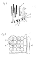
- a magnetic separation plate for use in methods employing magnetic particles, said magnetic separation plate comprising a support plate and magnetic pins in a predetermined geometrical arrangement, said magnetic pins having a fastening portion, an intermediate portion and a separation portion and being fastened to said support plate at their fastening portion, wherein said magnetic pins are individually displaceable at their separation portion.
- the present invention features an advantageous possibility to establish reliable and automatable methods for magnetic separation, as the latter require the process of coupling a multiwell plate and the magnetic separation plate to be reversible.
- the solution according to the present invention is particularly useful in the context of striving to minimize the dimensions of separation devices in favor of enhancing sample throughput.
- Inherent flexibility and/or flexible fastening of the magnetic pins are not negatively affected by reducing the device's or system's size and therefore the distances between the distinct elements.
- Multiwell plates with recesses of comparatively small diameters with relatively high tolerances may be used in the system according to the invention, which simplifies the production of such plates and reduces the respective costs.
- the homogeneity and/or overall intensity of the magnetic field acting on the magnetic particles can be affected in a negative manner.
- recesses that are significantly wider than the magnetic pins to be inserted inevitably lead to an increase of the distance between pin and sample, thus decreasing the magnetic force the particles are exposed to.
- the tolerances in the positions of the wells may cause an inhomogeneous magnetic field, since the distances between distinct pins and recesses may vary compared to each other.
- the present invention enables the artisan to apply a homogeneous field throughout the wells of the multiwell plate, said field being close to its maximum possible intensity, since small recesses can be used with the magnetic pins adapting the position of their separation portion to possible deviations of the geometrical arrangement of the recesses.
- a “magnetic separation plate” is a device useful for the separation of magnetic particles. It comprises a “support plate” and “magnetic pins", wherein the “support plate” is typically an essentially flat device for bearing and holding the “magnetic pins” in a defined position which is usually perpendicular to the support plate. Said plate can be made of one or more parts and different materials such as metal or plastic. In a preferred embodiment, the plate is made of metal.
- the support plate comprises an upper and a lower plate fastened to each other.
- the "magnetic pins” are essentially rod-shaped magnetic or magnetizable structures.
- the length of the magnetic pins is preferably 2-100 mm, more preferably 15-50 mm. Their diameter is preferably 1-20 mm, more preferably 2-6 mm.
- the pins comprise a "fastening portion", an "intermediate portion” and a "separation portion".
- this tripartite structure is not necessarily to be understood as an assembly of morphologically distinct and visually clearly separable or distinguishable structures. It is rather preferred that the different portions are integrally linked to each other in a manner such that there is no visible transition between them.
- the “fastening portion” is the portion at the end of the pin at which it is fixed to the support plate. If the “support plate” comprises an upper and a lower plate fastened to each other, the “fastening portion” is preferably embedded in between the upper and the lower plate.
- the “separation portion” is located at the end of the pin opposite to the fastening portion and separates the magnetic particles within the wells of a multiwell plate. A part or all of said “separation portion” is inserted reversibly into recesses within a multiwell plate. Said “separation portion” is morphologically preadapted to fit into said recesses. Therefore, in a preferred embodiment, the “separation portion” has a rounded-off tip at the end of the pin opposite of the fastening portion.
- the “separation portion” can be made of flexible and/or rigid material. Preferably, it is made of the same material as the remainder of the magnetic pin.
- the “intermediate portion” designates an integral portion of the magnetic pin located between and physically coupling the "fastening portion” and the “separation portion”.
- the “intermediate portion” is functionally distinct from the "fastening portion” and the “separation portion”.
- the “intermediate portion” can further be magnetic or magnetizable even though it does not directly contribute to the magnetic separation, and it can further be made of flexible and/or rigid material. It has preferably the same diameter and is preferably made of the same material as the "separation portion".
- the length of the intermediate portion is variable and can be very short.
- the angle between the pins and the support plate is essentially a right angle.
- the angle is between 80 and 100°, more preferably between 85° and 95°, most preferably 90°.
- a "predetermined geometrical arrangement" in the context of the invention means a defined spatial and directional relation between elements of a group of physical objects such as magnetic pins.
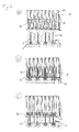
- “Individually displaceable” means that elements of a group of physical objects such as magnetic pins can be displaced independently from each other, i.e. moving one element does not affect other elements of this group.
- the magnetic pins are preferably laterally displaceable up to 5 mm from their default position at their separation portion, more preferably up to 1 mm.
- the magnetic pins return to their default position when external forces (as e.g. exerted by a microwell plate) are removed. Said return to the default position is caused by reset forces exerted by their specific structure and/or fastening to the support plate.
- the magnetic pins can be laterally displaceable up to 2 mm distance from their default position, more preferably up to 0.2 mm.
- a further aspect of the invention is the magnetic separation plate described above, wherein the magnetic pins are flexibly fastened to said support plate.
- “Flexibly fastened” means that the pins are not attached to the support plate in a rigid manner, but can be tilted with respect to the support plate such that the pins can be laterally displaced at their separation portion.
- the magnetic pins are fastened to the support plate via a holder containing one or more flexible elements.
- a "holder” in the context of the invention is a mount for the magnetic pins and can for example be a plug, a cone, or a ball or any other object capable of holding a magnetic pin at its fastening portion.
- a “flexible element” is an element made of any material that is compressible and/or extendable in a reversible manner. Such material can be intrinsically flexible like e.g. silicone rubber or polysulfide rubber or any other type of rubber, a polyurethane compound, latex, but it can also be flexible due to its geometrical construction or shape, like e.g. a spring made of metal.
- a ball joint made of rigid material such as metal is also to be considered a flexible element in the context of the present invention, since it allows for individual displacement of the magnetic pins at their separation portion.
- said one or more flexible elements are an outer layer made of flexible material, wherein said outer layer covers a rigid core. More preferably, said outer layer comprises one or more O-rings as flexible elements. Most preferably, said outer layer consists of one or more O-rings as flexible elements. In a preferred embodiment, said holder is a plug. Said O-rings are preferably made of rubber.
- the magnetic pins are fastened to the support plate via a ball joint.
- the magnetic pins of the magnetic separation plate are flexible.
- the magnetic pins comprise a core containing two or more rigid elements that are displaceable with respect to each other, said magnetic pins further comprising a covering made of flexible material and embedding said rigid elements.
- Preferred rigid elements are balls or rings. More preferably, said rigid elements are cylinder-shaped discs.
- said flexible elements are wires.
- the magnetic separation plate comprises magnetic pins that are intrinsically flexible as well as flexibly fastened.
- the pins contain magnetic material or magnetizable material.
- the magnetic separation plate according to the invention can be used in a system comprising other elements it interacts with, the following is also an aspect of the invention:
- a magnetic separation system for use in methods employing magnetic particles comprising
- a “magnetic separation system” means a device or combination of devices suitable for the separation of components in a mixture by means of magnetic forces.
- a “multiwell plate” is a device for receiving liquid substances or mixtures in receptacles, the "wells". The latter are usually arranged in a defined geometrical pattern.
- the "multiwell plate” can e.g. have 6, 12, 24, 48, 96, 384, 480 or 1536 "wells", but is not restricted to these numbers.
- the plate can further be made of transparent material, allowing for the passage of light e.g. for detection purposes in a photometric assay.
- a “multiwell plate” is made of plastics. In a preferred embodiment, the plastic is polypropylene.
- a “multiwell plate” does not have any specific restrictions with regard to the shape, size or volume of its “wells”. Thus, a “multiwell plate” can be e.g. a deep-well plate, a microwell plate etc.
- Magnetic particles are a magnetic or magnetizable solid phases. These particles may be preadapted to bind specific materials such as biological materials. Preadaptation can for example be achieved chemically (e.g. adding functional groups like amino groups to the particle surface) or biologically (e.g. coating the particle surface with antibodies or specific nucleic acid binding motives). Further, the "magnetic particles” preferably comprise a silica surface such as glass, thus facilitating binding of e.g. nucleic acids in the presence of chaotropic agents.
- nucleic acids are agglutinated along with the magnetic particles.
- the agglutinate is separated from the original solvent by applying a magnetic field and performing a wash step. After one wash step, the nucleic acids are dissolved in a Tris buffer.
- Magnetic, porous glass is also available on the market that contains magnetic particles in a porous, particular glass matrix and is covered with a layer containing streptavidin.
- This product can be used to isolate biological materials, e.g., proteins or nucleic acids, if they are modified in a complex preparation step so that they bind covalently to biotin.
- Magnetizable particular adsorbents proved to be very efficient and suitable for automatic sample preparation.
- Ferrimagnetic and ferromagnetic as well as superparamagnetic pigments are used for this purpose.
- the most preferred MGPs and methods using magnetic glass particles are those described in WO 01/37291 . Particularly useful is the method according to R. Boom et al. (J Clin Microbiol. 28 (1990), 495-503 ).
- Reversibly means that a process can be reverted without damaging components of a system.
- the magnetic pins are "reversibly" inserted into the recesses of the multiwell plate, which means that pins and the recesses can be separated from one another by applying essentially the same force required as for insertion of the pins.
- the "separation position” is a position in which the separation portion of the magnetic pins is inserted into the recesses of the multiwell plate with all or a part of their separation portion such that a magnetic field caused by the pins acts upon the magnetic particles within the wells of the multiwell plate.
- the magnetic separation system according to the invention can advantageously be implemented into a larger analytical system.
- another aspect of the invention is an analytical system comprising the magnetic separation system according to the invention, said analytical system further comprising a pipetting module comprising a pipettor.
- An “analytical system” is an arrangement of components such as instruments interacting with each other with the ultimate aim to analyze a given sample.
- the "pipetting module” is one such component of an analytical system, wherein the pipettor, which may e.g. a robotic pipetting device, accomplishes aspirating and dispensing the sample, reagents or mixtures and thus transferring them between the other different components of said system.
- the pipettor which may e.g. a robotic pipetting device, accomplishes aspirating and dispensing the sample, reagents or mixtures and thus transferring them between the other different components of said system.
- one aspect of the invention is the following:
- An analytical system comprising the magnetic separation system as described above, said analytical system further comprising a multiwell plate handling module and/or a magnetic separation plate handling module.
- a “multiwell plate handling module” is a device for moving the multiwell plate in spatial relation to the magnetic separation plate. It comprises a holder for the multiwell plate such as a drawer, and further a component like a robotic pivot arm to move said holder with or without the multiwell plate.
- the “magnetic separation plate handling module” is a device for the handling of the magnetic separation plate according to the invention.
- the handling modules set out above may also comprise DC-motors for movement of the plates and opening/closing/pressing a plate cover, sensors to identify the type of plate, or a barcode reader for identifying the sample.
- the analytical system according to the invention further comprises one or more elements selected from the following group:
- a “reaction module” can comprise a variety of vessels like tubes or plates, in which a reaction for the analysis of the sample such as Polymerase Chain Reaction or hybridization of antibodies takes place.
- the outer limits or walls of such vessels are chemically inert such that they do not interfere with the analytical reaction taking place within. Details of the Polymerase Chain Reaction are described infra.
- a “detection module” can e.g. be an optical detection unit for detecting the result or the effect of the analysis procedure.
- An optical detection unit may comprise a light source, e.g. a xenon lamp, optics such as mirrors, lenses, optical filters, fiber optics for guiding and filtering the light, one or more reference channels, or a CCD camera.
- a “storage module” module stores the necessary reagents to bring about a chemical or biological reaction important for analysis of the sample in question. It can also contain further components useful for the method of the invention, e.g. disposables such as pipet tips or vessels to be used as reaction receptacles within the reaction module.
- the analytical system further comprises a control unit for controlling system components.
- control unit may comprise a software for ensuring that the different components of said analytical system work and interact correctly and with the correct timing, e.g. moving components such as the pipettor to the multiwell plate in a coordinated manner.
- the control unit may also comprise a processor running a real-time operating system (RTOS), which is a multitasking operating system intended for real-time applications.
- RTOS real-time operating system
- the system processor is capable of managing real-time constraints, i.e. operational deadlines from event to system response regardless of system load. It controls in real time that different units within the system operate and respond correctly according to given instructions.
- a further aspect of the present invention is a method for the separation of magnetic particles, said method comprising the steps:
- This method can be advantageously carried out with the magnetic separation plate and/or the magnetic separation system or analytical system according to the invention as described supra.
- the method according to the invention further comprises the step of retracting the magnetic pins from the recesses of the multiwell plate for removing the magnetic field from the magnetic particles after step c).
- Another aspect of the invention is the use of the magnetic separation plate according to the invention for the separation of magnetic particles.
- PCR Polymerase Chain Reaction
- PCR Polymerase Chain Reaction
- PCR typically employs two or more oligonucleotide primers that bind to a selected nucleic acid template (e.g. DNA or RNA).
- Primers useful for nucleic acid analysis include oligonucleotides capable of acting as a point of initiation of nucleic acid synthesis within the nucleic acid sequences of the microbial nucleic acid or quantitative standard nucleic acid.
- a primer can be purified from a restriction digest by conventional methods, or it can be produced synthetically.
- the primer is preferably single-stranded for maximum efficiency in amplification, but the primer can be double-stranded.
- Double-stranded primers are first denatured, i.e., treated to separate the strands.
- One method of denaturing double stranded nucleic acids is by heating.
- a "thermostable polymerase” is a polymerase enzyme that is heat stable, i.e., it is an enzyme that catalyzes the formation of primer extension products complementary to a template and does not irreversibly denature when subjected to the elevated temperatures for the time necessary to effect denaturation of double-stranded template nucleic acids.
- the synthesis is initiated at the 3' end of each primer and proceeds in the 5' to 3' direction along the template strand.
- Thermostable polymerases have been isolated from Thermus flavus, T. ruber, T. thermophilus, T. aquaticus, T. lacteus, T. rubens, Bacillus stearothermophilus, and Methanothermus fervidus. Nonetheless, polymerases that are not thermostable also can be employed in PCR assays provided the enzyme is replenished. If the template nucleic acid is double-stranded, it is necessary to separate the two strands before it can be used as a template in PCR. Strand separation can be accomplished by any suitable denaturing method including physical, chemical or enzymatic means.
- One method of separating the nucleic acid strands involves heating the nucleic acid until it is predominately denatured (e.g., greater than 50%, 60%, 70%, 80%, 90% or 95% denatured).
- the heating conditions necessary for denaturing template nucleic acid will depend, e.g., on the buffer salt concentration and the length and nucleotide composition of the nucleic acids being denatured, but typically range from about 90°C to about 105°C for a time depending on features of the reaction such as temperature and the nucleic acid length. Denaturation is typically performed for about 30 sec to 4 min (e.g., 1 min to 2 min 30 sec, or 1.5 min).
- the reaction mixture is allowed to cool to a temperature that promotes annealing of each primer to its target sequence on the microbial nucleic acid and/or quantitative standard nucleic acid.
- the temperature for annealing is usually from about 35°C to about 65°C (e.g., about 40°C to about 60°C; about 45°C to about 50°C).
- Annealing times can be from about 10 sec to about 1 min (e.g., about 20 sec to about 50 sec; about 30 sec to about 40 sec).
- the reaction mixture is then adjusted to a temperature at which the activity of the polymerase is promoted or optimized, i.e., a temperature sufficient for extension to occur from the annealed primer to generate products complementary to the nucleic acid to be analyzed.
- the temperature should be sufficient to synthesize an extension product from each primer that is annealed to a nucleic acid template, but should not be so high as to denature an extension product from its complementary template (e.g., the temperature for extension generally ranges from about 40° to 80°C (e.g., about 50°C to about 70°C; about 60°C).
- Extension times can be from about 10 sec to about 5 min (e.g., about 30 sec to about 4 min; about 1 min to about 3 min; about 1 min 30 sec to about 2 min).
- the newly synthesized strands form a double-stranded molecule that can be used in the succeeding steps of the reaction.
- the steps of strand separation, annealing, and elongation can be repeated as often as needed to produce the desired quantity of amplification products corresponding to the microbial nucleic acid and/or quantitative standard nucleic acid.
- the limiting factors in the reaction are the amounts of primers, thermostable enzyme, and nucleoside triphosphates present in the reaction.
- the cycling steps i.e., denaturation, annealing, and extension
- cycling steps For use in detection, the number of cycling steps will depend, e.g., on the nature of the sample. If the sample is a complex mixture of nucleic acids, more cycling steps will be required to amplify the target sequence sufficient for detection. Generally, the cycling steps are repeated at least about 20 times, but may be repeated as many as 40, 60, or even 100 times.
- Nucleic acid amplification reactions apart from PCR comprise the Ligase Chain Reaction (LCR; Wu D. Y. and Wallace R. B., Genomics 4 (1989) 560-69 ; and Barany F., Proc. Natl. Acad. Sci. USA 88 (1991)189-193 ); Polymerase Ligase Chain Reaction ( Barany F., PCR Methods and Applic. 1 (1991) 5-16 ); Gap-LCR ( WO 90/01069 ); Repair Chain Reaction ( EP 0439182 A2 ), 3SR ( Kwoh D. Y. et al., Proc. Natl. Acad. Sci.
- nucleic acid detection methods are known to the expert in the field and are described in standard textbooks as Sambrook J. et al., Molecular Cloning: A Laboratory Manual, Cold Spring Harbor Laboratory Press, Cold Spring Harbor, New York, 1989 and Ausubel F. et al.: Current Protocols in Molecular Biology 1987, J. Wiley and Sons, NY .
- the detection methods may include but are not limited to the binding or intercalating of specific dyes as ethidium bromide which intercalates into the double-stranded DNA and changes its fluorescence thereafter.
- the purified nucleic acid may also be separated by electrophoretic methods optionally after a restriction digest and visualized thereafter. There are also probe-based assays which exploit the oligonucleotide hybridization to specific sequences and subsequent detection of the hybrid. It is also possible to sequence the nucleic acid after further steps known to the expert in the field.
- a useful template-dependent nucleic acid polymerase is the ZO5 DNA polymerase and mutations thereof.
- Other template-dependent nucleic acid polymerases comprise e.g. Taq polymerase and Tth Polymerase.
Landscapes
- Measuring Or Testing Involving Enzymes Or Micro-Organisms (AREA)
Priority Applications (1)
| Application Number | Priority Date | Filing Date | Title |
|---|---|---|---|
| EP08105576.6A EP2177271B8 (de) | 2008-10-15 | 2008-10-15 | Magnetisches Trennsystem mit flexiblen magnetischen Stiften und zugehöriges Verfahren |
Applications Claiming Priority (1)
| Application Number | Priority Date | Filing Date | Title |
|---|---|---|---|
| EP08105576.6A EP2177271B8 (de) | 2008-10-15 | 2008-10-15 | Magnetisches Trennsystem mit flexiblen magnetischen Stiften und zugehöriges Verfahren |
Publications (3)
| Publication Number | Publication Date |
|---|---|
| EP2177271A1 true EP2177271A1 (de) | 2010-04-21 |
| EP2177271B1 EP2177271B1 (de) | 2019-11-13 |
| EP2177271B8 EP2177271B8 (de) | 2019-12-18 |
Family
ID=40506501
Family Applications (1)
| Application Number | Title | Priority Date | Filing Date |
|---|---|---|---|
| EP08105576.6A Active EP2177271B8 (de) | 2008-10-15 | 2008-10-15 | Magnetisches Trennsystem mit flexiblen magnetischen Stiften und zugehöriges Verfahren |
Country Status (1)
| Country | Link |
|---|---|
| EP (1) | EP2177271B8 (de) |
Cited By (3)
| Publication number | Priority date | Publication date | Assignee | Title |
|---|---|---|---|---|
| WO2014034908A1 (ja) * | 2012-08-31 | 2014-03-06 | 株式会社 東芝 | 検体検査装置 |
| US9625355B2 (en) | 2014-12-01 | 2017-04-18 | General Electric Company | Extraction of materials from regions of interest in a sample |
| WO2021203005A1 (en) * | 2020-04-03 | 2021-10-07 | Beckman Coulter, Inc. | Electromagnetic assemblies for processing fluids |
Citations (15)
| Publication number | Priority date | Publication date | Assignee | Title |
|---|---|---|---|---|
| US4683202A (en) | 1985-03-28 | 1987-07-28 | Cetus Corporation | Process for amplifying nucleic acid sequences |
| US4683195A (en) | 1986-01-30 | 1987-07-28 | Cetus Corporation | Process for amplifying, detecting, and/or-cloning nucleic acid sequences |
| US4800159A (en) | 1986-02-07 | 1989-01-24 | Cetus Corporation | Process for amplifying, detecting, and/or cloning nucleic acid sequences |
| WO1990001069A1 (en) | 1988-07-20 | 1990-02-08 | Segev Diagnostics, Inc. | Process for amplifying and detecting nucleic acid sequences |
| US4965188A (en) | 1986-08-22 | 1990-10-23 | Cetus Corporation | Process for amplifying, detecting, and/or cloning nucleic acid sequences using a thermostable enzyme |
| US4988618A (en) * | 1987-11-16 | 1991-01-29 | Gene-Trak Systems | Magnetic separation device and methods for use in heterogeneous assays |
| EP0439182A2 (de) | 1990-01-26 | 1991-07-31 | Abbott Laboratories | Verbessertes Verfahren zur Amplifikation von Nuklein säurezielsequenz, einsetzbar für die Polymerase und Ligasekettenreaktion |
| WO1991012079A1 (en) | 1990-02-13 | 1991-08-22 | Amersham International Plc | Method to isolate macromolecules using magnetically attractable beads which do not specifically bind the macromolecules |
| WO1992008808A1 (en) | 1990-11-14 | 1992-05-29 | Siska Diagnostics, Inc. | Non-isotopic detection of nucleic acids using a polystyrene support-based sandwich hybridization assay and compositions useful therefor |
| US5130238A (en) | 1988-06-24 | 1992-07-14 | Cangene Corporation | Enhanced nucleic acid amplification process |
| GB2300258A (en) * | 1995-04-28 | 1996-10-30 | Philip John Jewess | A separation device for magnetisable particles |
| US5779907A (en) | 1996-12-06 | 1998-07-14 | Systems Research Laboratories, Inc. | Magnetic microplate separator |
| WO2001037291A1 (en) | 1999-11-17 | 2001-05-25 | Roche Diagnostics Gmbh | Magnetic glass particles, method for their preparation and uses thereof |
| WO2005044460A2 (en) * | 2003-11-11 | 2005-05-19 | Thermo Electron Oy | Particle separating device |
| EP1681570A2 (de) * | 2003-06-19 | 2006-07-19 | Abbott Laboratories | Vorrichtung und Verfahren zur Handhabung von Analyseflüssigkeiten |
Family Cites Families (1)
| Publication number | Priority date | Publication date | Assignee | Title |
|---|---|---|---|---|
| US7534081B2 (en) * | 2005-05-24 | 2009-05-19 | Festo Corporation | Apparatus and method for transferring samples from a source to a target |
-
2008
- 2008-10-15 EP EP08105576.6A patent/EP2177271B8/de active Active
Patent Citations (17)
| Publication number | Priority date | Publication date | Assignee | Title |
|---|---|---|---|---|
| US4683202B1 (de) | 1985-03-28 | 1990-11-27 | Cetus Corp | |
| US4683202A (en) | 1985-03-28 | 1987-07-28 | Cetus Corporation | Process for amplifying nucleic acid sequences |
| US4683195A (en) | 1986-01-30 | 1987-07-28 | Cetus Corporation | Process for amplifying, detecting, and/or-cloning nucleic acid sequences |
| US4683195B1 (de) | 1986-01-30 | 1990-11-27 | Cetus Corp | |
| US4800159A (en) | 1986-02-07 | 1989-01-24 | Cetus Corporation | Process for amplifying, detecting, and/or cloning nucleic acid sequences |
| US4965188A (en) | 1986-08-22 | 1990-10-23 | Cetus Corporation | Process for amplifying, detecting, and/or cloning nucleic acid sequences using a thermostable enzyme |
| US4988618A (en) * | 1987-11-16 | 1991-01-29 | Gene-Trak Systems | Magnetic separation device and methods for use in heterogeneous assays |
| US5130238A (en) | 1988-06-24 | 1992-07-14 | Cangene Corporation | Enhanced nucleic acid amplification process |
| WO1990001069A1 (en) | 1988-07-20 | 1990-02-08 | Segev Diagnostics, Inc. | Process for amplifying and detecting nucleic acid sequences |
| EP0439182A2 (de) | 1990-01-26 | 1991-07-31 | Abbott Laboratories | Verbessertes Verfahren zur Amplifikation von Nuklein säurezielsequenz, einsetzbar für die Polymerase und Ligasekettenreaktion |
| WO1991012079A1 (en) | 1990-02-13 | 1991-08-22 | Amersham International Plc | Method to isolate macromolecules using magnetically attractable beads which do not specifically bind the macromolecules |
| WO1992008808A1 (en) | 1990-11-14 | 1992-05-29 | Siska Diagnostics, Inc. | Non-isotopic detection of nucleic acids using a polystyrene support-based sandwich hybridization assay and compositions useful therefor |
| GB2300258A (en) * | 1995-04-28 | 1996-10-30 | Philip John Jewess | A separation device for magnetisable particles |
| US5779907A (en) | 1996-12-06 | 1998-07-14 | Systems Research Laboratories, Inc. | Magnetic microplate separator |
| WO2001037291A1 (en) | 1999-11-17 | 2001-05-25 | Roche Diagnostics Gmbh | Magnetic glass particles, method for their preparation and uses thereof |
| EP1681570A2 (de) * | 2003-06-19 | 2006-07-19 | Abbott Laboratories | Vorrichtung und Verfahren zur Handhabung von Analyseflüssigkeiten |
| WO2005044460A2 (en) * | 2003-11-11 | 2005-05-19 | Thermo Electron Oy | Particle separating device |
Non-Patent Citations (11)
| Title |
|---|
| ABRAMSON R. D.; MYERS T. W., CURR OPIN BIOTECHNOL, vol. 4, 1993, pages 41 - 47 |
| ALDERTON R. P. ET AL., S., ANAL. BIOCHEM., vol. 201, 1992, pages 166 - 169 |
| AUSUBEL F. ET AL.: "Current Protocols in Molecular Biology", 1987, J. WILEY AND SONS |
| BARANY F., PCR METHODS AND APPLIC., vol. 1, 1991, pages 5 - 16 |
| BARANY F., PROC. NATL. ACAD. SCI. USA, vol. 88, 1991, pages 189 - 193 |
| GUATELLI J.C. ET AL., PROC. NATL. ACAD. SCI. USA, vol. 87, 1990, pages 1874 - 1878 |
| KWOH D. Y. ET AL., PROC. NATL. ACAD. SCI. USA, vol. 86, 1989, pages 1173 - 1177 |
| R. BOOM ET AL., J CLIN MICROBIOL., vol. 28, 1990, pages 495 - 503 |
| SAMBROOK J. ET AL.: "Molecular Cloning: A Laboratory Manual", 1989, COLD SPRING HARBOR LABORATORY PRESS |
| WHELEN A. C.; PERSING D. H., ANNU. REV. MICROBIOL., vol. 50, 1996, pages 349 - 373 |
| WU D. Y.; WALLACE R. B., GENOMICS, vol. 4, 1989, pages 560 - 69 |
Cited By (9)
| Publication number | Priority date | Publication date | Assignee | Title |
|---|---|---|---|---|
| WO2014034908A1 (ja) * | 2012-08-31 | 2014-03-06 | 株式会社 東芝 | 検体検査装置 |
| JP2014062901A (ja) * | 2012-08-31 | 2014-04-10 | Toshiba Corp | 検体検査装置 |
| CN103765214A (zh) * | 2012-08-31 | 2014-04-30 | 株式会社东芝 | 检测体检查装置 |
| CN103765214B (zh) * | 2012-08-31 | 2015-10-21 | 株式会社东芝 | 检测体检查装置 |
| US9470700B2 (en) | 2012-08-31 | 2016-10-18 | Toshiba Medical Systems Corporation | Automatic analyzer |
| US9625355B2 (en) | 2014-12-01 | 2017-04-18 | General Electric Company | Extraction of materials from regions of interest in a sample |
| US10494627B2 (en) | 2014-12-01 | 2019-12-03 | General Electric Company | Extraction of materials from regions of interest in a sample |
| WO2021203005A1 (en) * | 2020-04-03 | 2021-10-07 | Beckman Coulter, Inc. | Electromagnetic assemblies for processing fluids |
| CN115551641A (zh) * | 2020-04-03 | 2022-12-30 | 贝克曼库尔特有限公司 | 用于处理流体的电磁组件 |
Also Published As
| Publication number | Publication date |
|---|---|
| EP2177271B1 (de) | 2019-11-13 |
| EP2177271B8 (de) | 2019-12-18 |
Similar Documents
| Publication | Publication Date | Title |
|---|---|---|
| US20130284654A1 (en) | Magnetic Separation System Comprising Flexible Magnetic Pins | |
| US10632467B2 (en) | Cartridge, kit and method for manipulating liquids having biological samples | |
| EP2145955B1 (de) | Nukleinsäureamplifikation auf Basis von Kügelchenemulsion | |
| AU2009201529B2 (en) | Apparatus For Polynucleotide Detection and Quantitation | |
| US20220401957A1 (en) | Information storage using enzymatic dna synthesis and digital microfluidics | |
| WO2009029728A1 (en) | Alternative nucleic acid sequencing methods | |
| WO2010077859A2 (en) | Nucleic acid amplification and sequencing on a droplet actuator | |
| JP2005537002A (ja) | 新規な一体化したマイクロアレイ分析 | |
| CN108823092B (zh) | 一种液滴芯片核酸分析系统及其分析方法 | |
| EP3080267A1 (de) | Probenaufbereitungsverfahren und -vorrichtung | |
| JP6665090B2 (ja) | マイクロ流体装置並びにかかる装置に試薬及び生体試料を供給するための配置 | |
| US20240123447A1 (en) | Methods and related aspects for multiplexed analyte detection using sequential magnetic particle elution | |
| US20170101665A1 (en) | Nucleic Acid Amplification With Integrated Multiplex Detection | |
| EP2177271B1 (de) | Magnetisches Trennsystem mit flexiblen magnetischen Stiften und zugehöriges Verfahren | |
| Obata et al. | Recent developments in laboratory automation using magnetic particles for genome analysis | |
| US7763424B2 (en) | Method of removing air bubbles from hybridization solution of microarray-coverslip assembly and microarray kit for the same | |
| US20250051834A1 (en) | Single-Cell Epigenomic Profiling Using Droplet Fluidics and Hydrogels | |
| JP2024526921A (ja) | 標的ポリヌクレオチドを配列決定するための組成物、キット及び方法 | |
| AU8365101A (en) | System and apparatus for sequential processing of analytes |
Legal Events
| Date | Code | Title | Description |
|---|---|---|---|
| PUAI | Public reference made under article 153(3) epc to a published international application that has entered the european phase |
Free format text: ORIGINAL CODE: 0009012 |
|
| AK | Designated contracting states |
Kind code of ref document: A1 Designated state(s): AT BE BG CH CY CZ DE DK EE ES FI FR GB GR HR HU IE IS IT LI LT LU LV MC MT NL NO PL PT RO SE SI SK TR |
|
| AX | Request for extension of the european patent |
Extension state: AL BA MK RS |
|
| 17P | Request for examination filed |
Effective date: 20101021 |
|
| AKX | Designation fees paid |
Designated state(s): AT BE BG CH CY CZ DE DK EE ES FI FR GB GR HR HU IE IS IT LI LT LU LV MC MT NL NO PL PT RO SE SI SK TR |
|
| 17Q | First examination report despatched |
Effective date: 20101216 |
|
| STAA | Information on the status of an ep patent application or granted ep patent |
Free format text: STATUS: EXAMINATION IS IN PROGRESS |
|
| GRAP | Despatch of communication of intention to grant a patent |
Free format text: ORIGINAL CODE: EPIDOSNIGR1 |
|
| STAA | Information on the status of an ep patent application or granted ep patent |
Free format text: STATUS: GRANT OF PATENT IS INTENDED |
|
| INTG | Intention to grant announced |
Effective date: 20190618 |
|
| GRAS | Grant fee paid |
Free format text: ORIGINAL CODE: EPIDOSNIGR3 |
|
| GRAA | (expected) grant |
Free format text: ORIGINAL CODE: 0009210 |
|
| STAA | Information on the status of an ep patent application or granted ep patent |
Free format text: STATUS: THE PATENT HAS BEEN GRANTED |
|
| GRAT | Correction requested after decision to grant or after decision to maintain patent in amended form |
Free format text: ORIGINAL CODE: EPIDOSNCDEC |
|
| AK | Designated contracting states |
Kind code of ref document: B1 Designated state(s): AT BE BG CH CY CZ DE DK EE ES FI FR GB GR HR HU IE IS IT LI LT LU LV MC MT NL NO PL PT RO SE SI SK TR |
|
| REG | Reference to a national code |
Ref country code: GB Ref legal event code: FG4D |
|
| REG | Reference to a national code |
Ref country code: AT Ref legal event code: REF Ref document number: 1201114 Country of ref document: AT Kind code of ref document: T Effective date: 20191115 Ref country code: CH Ref legal event code: EP |
|
| RAP2 | Party data changed (patent owner data changed or rights of a patent transferred) |
Owner name: F. HOFFMANN-LA ROCHE AG Owner name: ROCHE DIAGNOSTICS GMBH |
|
| REG | Reference to a national code |
Ref country code: CH Ref legal event code: PK Free format text: BERICHTIGUNG B8 |
|
| REG | Reference to a national code |
Ref country code: DE Ref legal event code: R096 Ref document number: 602008061619 Country of ref document: DE |
|
| REG | Reference to a national code |
Ref country code: IE Ref legal event code: FG4D |
|
| REG | Reference to a national code |
Ref country code: NL Ref legal event code: MP Effective date: 20191113 |
|
| REG | Reference to a national code |
Ref country code: LT Ref legal event code: MG4D |
|
| PG25 | Lapsed in a contracting state [announced via postgrant information from national office to epo] |
Ref country code: LT Free format text: LAPSE BECAUSE OF FAILURE TO SUBMIT A TRANSLATION OF THE DESCRIPTION OR TO PAY THE FEE WITHIN THE PRESCRIBED TIME-LIMIT Effective date: 20191113 Ref country code: NL Free format text: LAPSE BECAUSE OF FAILURE TO SUBMIT A TRANSLATION OF THE DESCRIPTION OR TO PAY THE FEE WITHIN THE PRESCRIBED TIME-LIMIT Effective date: 20191113 Ref country code: ES Free format text: LAPSE BECAUSE OF FAILURE TO SUBMIT A TRANSLATION OF THE DESCRIPTION OR TO PAY THE FEE WITHIN THE PRESCRIBED TIME-LIMIT Effective date: 20191113 Ref country code: SE Free format text: LAPSE BECAUSE OF FAILURE TO SUBMIT A TRANSLATION OF THE DESCRIPTION OR TO PAY THE FEE WITHIN THE PRESCRIBED TIME-LIMIT Effective date: 20191113 Ref country code: LV Free format text: LAPSE BECAUSE OF FAILURE TO SUBMIT A TRANSLATION OF THE DESCRIPTION OR TO PAY THE FEE WITHIN THE PRESCRIBED TIME-LIMIT Effective date: 20191113 Ref country code: PT Free format text: LAPSE BECAUSE OF FAILURE TO SUBMIT A TRANSLATION OF THE DESCRIPTION OR TO PAY THE FEE WITHIN THE PRESCRIBED TIME-LIMIT Effective date: 20200313 Ref country code: NO Free format text: LAPSE BECAUSE OF FAILURE TO SUBMIT A TRANSLATION OF THE DESCRIPTION OR TO PAY THE FEE WITHIN THE PRESCRIBED TIME-LIMIT Effective date: 20200213 Ref country code: GR Free format text: LAPSE BECAUSE OF FAILURE TO SUBMIT A TRANSLATION OF THE DESCRIPTION OR TO PAY THE FEE WITHIN THE PRESCRIBED TIME-LIMIT Effective date: 20200214 Ref country code: PL Free format text: LAPSE BECAUSE OF FAILURE TO SUBMIT A TRANSLATION OF THE DESCRIPTION OR TO PAY THE FEE WITHIN THE PRESCRIBED TIME-LIMIT Effective date: 20191113 Ref country code: FI Free format text: LAPSE BECAUSE OF FAILURE TO SUBMIT A TRANSLATION OF THE DESCRIPTION OR TO PAY THE FEE WITHIN THE PRESCRIBED TIME-LIMIT Effective date: 20191113 Ref country code: BG Free format text: LAPSE BECAUSE OF FAILURE TO SUBMIT A TRANSLATION OF THE DESCRIPTION OR TO PAY THE FEE WITHIN THE PRESCRIBED TIME-LIMIT Effective date: 20200213 |
|
| PG25 | Lapsed in a contracting state [announced via postgrant information from national office to epo] |
Ref country code: IS Free format text: LAPSE BECAUSE OF FAILURE TO SUBMIT A TRANSLATION OF THE DESCRIPTION OR TO PAY THE FEE WITHIN THE PRESCRIBED TIME-LIMIT Effective date: 20200313 Ref country code: HR Free format text: LAPSE BECAUSE OF FAILURE TO SUBMIT A TRANSLATION OF THE DESCRIPTION OR TO PAY THE FEE WITHIN THE PRESCRIBED TIME-LIMIT Effective date: 20191113 |
|
| PG25 | Lapsed in a contracting state [announced via postgrant information from national office to epo] |
Ref country code: RO Free format text: LAPSE BECAUSE OF FAILURE TO SUBMIT A TRANSLATION OF THE DESCRIPTION OR TO PAY THE FEE WITHIN THE PRESCRIBED TIME-LIMIT Effective date: 20191113 Ref country code: CZ Free format text: LAPSE BECAUSE OF FAILURE TO SUBMIT A TRANSLATION OF THE DESCRIPTION OR TO PAY THE FEE WITHIN THE PRESCRIBED TIME-LIMIT Effective date: 20191113 Ref country code: EE Free format text: LAPSE BECAUSE OF FAILURE TO SUBMIT A TRANSLATION OF THE DESCRIPTION OR TO PAY THE FEE WITHIN THE PRESCRIBED TIME-LIMIT Effective date: 20191113 Ref country code: DK Free format text: LAPSE BECAUSE OF FAILURE TO SUBMIT A TRANSLATION OF THE DESCRIPTION OR TO PAY THE FEE WITHIN THE PRESCRIBED TIME-LIMIT Effective date: 20191113 |
|
| REG | Reference to a national code |
Ref country code: DE Ref legal event code: R097 Ref document number: 602008061619 Country of ref document: DE |
|
| REG | Reference to a national code |
Ref country code: AT Ref legal event code: MK05 Ref document number: 1201114 Country of ref document: AT Kind code of ref document: T Effective date: 20191113 |
|
| PG25 | Lapsed in a contracting state [announced via postgrant information from national office to epo] |
Ref country code: SK Free format text: LAPSE BECAUSE OF FAILURE TO SUBMIT A TRANSLATION OF THE DESCRIPTION OR TO PAY THE FEE WITHIN THE PRESCRIBED TIME-LIMIT Effective date: 20191113 |
|
| PLBE | No opposition filed within time limit |
Free format text: ORIGINAL CODE: 0009261 |
|
| STAA | Information on the status of an ep patent application or granted ep patent |
Free format text: STATUS: NO OPPOSITION FILED WITHIN TIME LIMIT |
|
| 26N | No opposition filed |
Effective date: 20200814 |
|
| PG25 | Lapsed in a contracting state [announced via postgrant information from national office to epo] |
Ref country code: SI Free format text: LAPSE BECAUSE OF FAILURE TO SUBMIT A TRANSLATION OF THE DESCRIPTION OR TO PAY THE FEE WITHIN THE PRESCRIBED TIME-LIMIT Effective date: 20191113 Ref country code: AT Free format text: LAPSE BECAUSE OF FAILURE TO SUBMIT A TRANSLATION OF THE DESCRIPTION OR TO PAY THE FEE WITHIN THE PRESCRIBED TIME-LIMIT Effective date: 20191113 |
|
| PG25 | Lapsed in a contracting state [announced via postgrant information from national office to epo] |
Ref country code: IT Free format text: LAPSE BECAUSE OF FAILURE TO SUBMIT A TRANSLATION OF THE DESCRIPTION OR TO PAY THE FEE WITHIN THE PRESCRIBED TIME-LIMIT Effective date: 20191113 |
|
| PG25 | Lapsed in a contracting state [announced via postgrant information from national office to epo] |
Ref country code: LU Free format text: LAPSE BECAUSE OF NON-PAYMENT OF DUE FEES Effective date: 20201015 Ref country code: MC Free format text: LAPSE BECAUSE OF FAILURE TO SUBMIT A TRANSLATION OF THE DESCRIPTION OR TO PAY THE FEE WITHIN THE PRESCRIBED TIME-LIMIT Effective date: 20191113 |
|
| REG | Reference to a national code |
Ref country code: BE Ref legal event code: MM Effective date: 20201031 |
|
| PG25 | Lapsed in a contracting state [announced via postgrant information from national office to epo] |
Ref country code: BE Free format text: LAPSE BECAUSE OF NON-PAYMENT OF DUE FEES Effective date: 20201031 |
|
| PG25 | Lapsed in a contracting state [announced via postgrant information from national office to epo] |
Ref country code: IE Free format text: LAPSE BECAUSE OF NON-PAYMENT OF DUE FEES Effective date: 20201015 |
|
| PG25 | Lapsed in a contracting state [announced via postgrant information from national office to epo] |
Ref country code: TR Free format text: LAPSE BECAUSE OF FAILURE TO SUBMIT A TRANSLATION OF THE DESCRIPTION OR TO PAY THE FEE WITHIN THE PRESCRIBED TIME-LIMIT Effective date: 20191113 Ref country code: MT Free format text: LAPSE BECAUSE OF FAILURE TO SUBMIT A TRANSLATION OF THE DESCRIPTION OR TO PAY THE FEE WITHIN THE PRESCRIBED TIME-LIMIT Effective date: 20191113 Ref country code: CY Free format text: LAPSE BECAUSE OF FAILURE TO SUBMIT A TRANSLATION OF THE DESCRIPTION OR TO PAY THE FEE WITHIN THE PRESCRIBED TIME-LIMIT Effective date: 20191113 |
|
| PGFP | Annual fee paid to national office [announced via postgrant information from national office to epo] |
Ref country code: GB Payment date: 20250923 Year of fee payment: 18 |
|
| PGFP | Annual fee paid to national office [announced via postgrant information from national office to epo] |
Ref country code: FR Payment date: 20250924 Year of fee payment: 18 |
|
| REG | Reference to a national code |
Ref country code: CH Ref legal event code: U11 Free format text: ST27 STATUS EVENT CODE: U-0-0-U10-U11 (AS PROVIDED BY THE NATIONAL OFFICE) Effective date: 20251101 |
|
| PGFP | Annual fee paid to national office [announced via postgrant information from national office to epo] |
Ref country code: DE Payment date: 20250923 Year of fee payment: 18 |
|
| PGFP | Annual fee paid to national office [announced via postgrant information from national office to epo] |
Ref country code: CH Payment date: 20251101 Year of fee payment: 18 |