EP2177314A2 - Ergonomische Drosselhebelsteuerung und Handauflage - Google Patents
Ergonomische Drosselhebelsteuerung und Handauflage Download PDFInfo
- Publication number
- EP2177314A2 EP2177314A2 EP09252451A EP09252451A EP2177314A2 EP 2177314 A2 EP2177314 A2 EP 2177314A2 EP 09252451 A EP09252451 A EP 09252451A EP 09252451 A EP09252451 A EP 09252451A EP 2177314 A2 EP2177314 A2 EP 2177314A2
- Authority
- EP
- European Patent Office
- Prior art keywords
- lever
- tool
- hand
- recited
- switch
- Prior art date
- Legal status (The legal status is an assumption and is not a legal conclusion. Google has not performed a legal analysis and makes no representation as to the accuracy of the status listed.)
- Granted
Links
Images

Classifications
-
- B—PERFORMING OPERATIONS; TRANSPORTING
- B24—GRINDING; POLISHING
- B24B—MACHINES, DEVICES, OR PROCESSES FOR GRINDING OR POLISHING; DRESSING OR CONDITIONING OF ABRADING SURFACES; FEEDING OF GRINDING, POLISHING, OR LAPPING AGENTS
- B24B23/00—Portable grinding machines, e.g. hand-guided; Accessories therefor
- B24B23/02—Portable grinding machines, e.g. hand-guided; Accessories therefor with rotating grinding tools; Accessories therefor
-
- B—PERFORMING OPERATIONS; TRANSPORTING
- B24—GRINDING; POLISHING
- B24B—MACHINES, DEVICES, OR PROCESSES FOR GRINDING OR POLISHING; DRESSING OR CONDITIONING OF ABRADING SURFACES; FEEDING OF GRINDING, POLISHING, OR LAPPING AGENTS
- B24B23/00—Portable grinding machines, e.g. hand-guided; Accessories therefor
- B24B23/04—Portable grinding machines, e.g. hand-guided; Accessories therefor with oscillating grinding tools; Accessories therefor
- B24B23/043—Portable grinding machines, e.g. hand-guided; Accessories therefor with oscillating grinding tools; Accessories therefor reciprocatingly driven by a pneumatic or hydraulic piston
-
- Y—GENERAL TAGGING OF NEW TECHNOLOGICAL DEVELOPMENTS; GENERAL TAGGING OF CROSS-SECTIONAL TECHNOLOGIES SPANNING OVER SEVERAL SECTIONS OF THE IPC; TECHNICAL SUBJECTS COVERED BY FORMER USPC CROSS-REFERENCE ART COLLECTIONS [XRACs] AND DIGESTS
- Y10—TECHNICAL SUBJECTS COVERED BY FORMER USPC
- Y10T—TECHNICAL SUBJECTS COVERED BY FORMER US CLASSIFICATION
- Y10T74/00—Machine element or mechanism
- Y10T74/20—Control lever and linkage systems
- Y10T74/20576—Elements
- Y10T74/20582—Levers
- Y10T74/20612—Hand
- Y10T74/20618—Jointed
Definitions
- the present invention relates generally to throttle levers, and more particularly, to ergonomically designed throttle levers for use with handheld powered tools.
- Hand-held, portable, powered, non-vacuum or vacuum, non-rotary, rotary, orbital, and random-orbital sanders and other handheld abrading or abrasive tools are known. These tools generally have a motor, a housing for a motor, a grip over the housing, an abrading surface powered by the motor, an air-inlet port, an exhaust outlet, and a throttle-switch.
- the present inventor recognized that in order to use the throttle lever of presently available tools an operator is required to arch his wrist while using the sander, which stresses the wrist and arm and, eventually can be the cause of chronic injuries, such as carpal tunnel syndrome. This happens in the tools that are so designed that the operator must press downwards on the throttle lever situated on the top of the housing while at the same time arching his or her wrist out of the way of the attached air hose. For pneumatic sanders, the operator must, additionally, keep out of the way of the power cord, and/or dust and air exhaust.
- a handheld, pneumatic, surface-treating device has a relatively large switch that must be held by the operator's gripping hand as the surface treating device is operated, and additionally, there is an air-inlet and exhaust extending out from the housing under the switch. Because this device lacks a hand/wrist support, the operator's wrist must be arched and his or her hand must be cupped in order to hold the switch and simultaneously maneuver the tool on the surface to be treated.
- Another tool similar in structure, features a dust-bag outlet extending from beneath the switch, but provides no stable component upon which the operator's wrist or forearm can rest.
- Another tool offers an exhaust duct designed to have a curved shape making it unsuitable for supporting a wrist and to be positioned below the level of the switch, making the duct unavailable for providing a wrist or forearm rest, even if the shape of the duct was more suitable.
- the present inventor realized that although the more recent handheld abrasive tools are somewhat more user friendly, in that they offer a hand support even thought they maintain the switch under the throttle, they still suffer from several design flaws.
- their throttle switch is separate and spaced apart from the portion of the tool body that is intended to function as a hand-support. The space between the throttle switch and the hand-support creates a hand-skin pinching hazard.
- these models require an operator to press the front part (finger area) of his/her hand downwards on the throttle lever situated on the top of the housing and to stop the action of the tool, the operator must stop pressing downward with the front part of his hand.
- the present inventor conceived a set of principles that provide abrasive and abrading tool assemblies having a motor, a housing over the motor, a grip over the housing, an air-inlet port, an exhaust outlet, and a throttle-switch-hand-support element.
- the principles behind the present invention provide for a one-piece hand-support element unit that not only supports an operator's hand, but provides for throttle control as well resulting in effectively relieving stress on an operator's wrist and forearm.
- the throttle-switch-hand-support is attached to the abrading tool and extends over the air-inlet port and dust-bag outlets.
- the one-piece design of the throttle-switch-hand-support eliminates the need for an operator to lift his hand off of a switch in order to reduce rotating velocity. To reduce or increase velocity using the switch of the present invention, all the operator has to do is to rock his hand back or forth, respectively, while allowing the weight of the hand to remain supported by the throttle-switch-hand-support.
- the abrading tool is a rotary tool.
- the air-inlet port may be replaced by an electric power cord in electrically powered tools.
- a lever made according to the principles of the present invention are made possible by providing for a lever for controlling a throttle switch, comprising an elongate lever having an upper surface, a first end, and a second end, the lever bent across its length producing an angle of less than 180 degrees between the upper surface of the first end and the upper surface of the second end so as to enable control of a throttle switch by hand-rocking the lever to rotate about its angle's vertex to exert pressure on or release pressure from the throttle switch, the lever having a length sufficient so as to support the fingers and palm of a user, wherein the throttle switch is a switch on a hand-held power tool, and further having attachment tabs positioned on opposing sides of the lever, the attachment tabs providing for attachment of the lever to the handheld tool.
- the length of the lever is designed to extend over an exhaust-outlet or an air-intake of the hand-held power tool so as to protect the user's hand from coming into contact with the tool's exhaust-outlet or air-intake and has a check tab formed from a partial cut-out of the lever, the check tab positioned so as to extend to the handheld tool to limit the extent the lever can rotate.
- the lever is also taught as used in combination with a handheld tool, comprising a handheld power tool having a throttle switch, and an elongate lever for controlling the throttle switch, the lever comprising an upper surface, a first end, and a second end, the lever bent across its length producing a vertex and an angle of less than 180 degrees between the upper surface of the first end and the upper surface of the second end so as to enable control of a throttle switch by hand-rocking the lever to rotate about its angle's vertex so as to exert pressure on or release pressure from the throttle switch, the lever having a length sufficient so as to support the fingers and palm of a user, further having attachment tabs positioned on opposing sides of the lever, the attachment tabs providing for attachment of the lever to the tool, and designed of a length to extend over an exhaust-outlet and/or an air-intake of the tool so as to protect user's hand from coming into contact with the tool's exhaust-outlet or air-intake.
- the lever is contemplated for use with any handheld power tool, including but not limited to an abrading tool, a sanding tool, a non-rotary action sanding tool, a rotary action sanding tool, an orbital action sanding tool, a random-orbital action sanding tool, a vacuum sanding tool, a non-vacuum sanding tool, and a vacuum random-orbital action sanding tool.
- an abrading tool including but not limited to an abrading tool, a sanding tool, a non-rotary action sanding tool, a rotary action sanding tool, an orbital action sanding tool, a random-orbital action sanding tool, a vacuum sanding tool, a non-vacuum sanding tool, and a vacuum random-orbital action sanding tool.
- the disclosed invention is disposed to embodiments in various sizes, shapes, and forms.
- the overall size of the lever could increase or decrease depending on which size model of a particular tool the handle is to be employed.
- the handle could be provided in various sizes to take into consideration the size of the operator's hand.
- the general shape of the handle could be changed, such as making the extension of the handle wider, longer, or even shaped to have curved edges or a rounded surface. Therefore, the embodiments described herein are provided with the understanding that the present disclosure is intended as illustrative and is not intended to limit the invention to the embodiments described herein.
- the present invention is particularly directed to a throttle-switch-hand-support lever for use on abrasive or abrading tools.
- the tools according to the principles of the present invention are generally provided with a motor, a housing over the motor, a grip over the housing, an air-inlet port, an exhaust outlet, and an elongated, angled, throttle-switch-hand-support lever to provide support an operator's hand so as to reduce stress on the operator's wrist and forearm.
- the present invention may be utilized with a variety of hand-held powered tools, which includes tools with non-rotary, rotary, orbital, and random-orbital actions, as well as tools that are non-vacuum or vacuum.
- One favored embodiment features a pneumatically powered abrading tool with a one-piece, continuous, elongated, angled, throttle-switch-hand-support lever extending from over the valve actuator switch to over the air-inlet and exhaust ports.
- FIGS. 1 - 3 provide various views of a throttle lever that does not incorporate the principles of the present invention
- FIGS. 4 - 6 provide various views of a presently available surface treatment tool fitted with the old style throttle lever.
- Tool 10 is designed to be held by one hand. Housing 26 , grip 18 over the housing, pad 24 having abrasive material 22 , such as sandpaper, attached thereto to be applied to the surface to be treated, air intake 28 , an exhaust extending from housing 26 , switch 16 , and short, flat switch lever 6 .
- the short, flat throttle lever 6 must be pressed downward to activate the motor.
- Lever 6 can not provide any support or protection for the operator's hand, as it is not long enough and it is not ergonomically shaped. Because the lever does not extend over the exhaust and intake area, it is not able to provide protection for the operator's hand from the effects of the exhaust and air intake. Thus, the operator must maintain his hand in an upwardly bent position to avoid the exhaust and air intake. A result of the operator having to maintain his hand in an upwardly bent position is that more weight and force from the front part of his hand is directed onto lever 6 . This, in turn, results in it being more difficult for the operator to release the pressure of the front of his hand on the lever to stop the action. The sum of these competing forces will likely cause an operator's hand to feel the stress and to tire easily while using such a tool.
- the principles of the present invention are taught herein using a hand-held power tool as an example.
- This tool provides for an elongated, angled, throttle-switch-hand-support lever.
- the lever of the present invention is elongated relative to the levers provided in presently available tools.
- the elongated lever is described as having two sections, an elongated first section on which the operator's fingers and the proximal part of his palm rests, and a second, shorter section providing support to the distal part of the operator's palm.
- the two sections are distinguished by a bend in the single piece of material used to form the lever. This bend creates a lever shaped in the form of a very shallow "v" having an offset vertex, which creates lever arms of different lengths.
- the offset vertex results in the lever having one longer section and one shorter section with their common boundary being the vertex of the angle, although it must be noted that the length of the two sections combined is greater than any known lever providing similar function.
- the underside of the vertex of the angled lever is also where the lever is structured so as to connect to the tool. This design provides for the longer first lever section to support the front part of an operator's hand, for the shorter second lever section to support the portion of hand nearer the wrist, for the operator to control the actuator switch using a simple rocking motion of the hand, and eliminates the need for any hand lifting movements that are required to increase or decrease the rotational velocity when using a tool not fitted with the present invention.
- the elongation of the lever means that the lever extends over and past the inlet and exhaust protecting the operator's hand from coming into contact with the exhaust or air-intake. Note that the old style lever ends some distance before the exhaust.
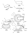
- This exemplary tool being a favored embodiment of the present invention, is illustrated in FIGS. 7 - 14 .
- FIG. 7 a perspective view, illustrates the top surface of ergonomic, elongate, angled, rocker throttle-switch-hand-support lever 5 of the present invention.
- Lever 5 is described as elongate, which means that it is considerably longer compared to currently available switch levers providing for the lever to protect the operator's hand from coming into contact with the exhaust or air-intake. This can be clearly observed by comparing the extension of the ergo-lever in FIG. 12 to the lack of extension in the lever illustrated in FIG. 6 .
- FIG. 8 a perspective view of the bottom surface of the lever, illustrates the structure provided for attaching the ergonomic lever to a tool, as is also illustrated in FIGS. 13 and 14 .
- the attachment structure consists of opposing attachment tabs 14 that extend downwards from lever 5 toward pin receiving apertures of tool 20.
- Attachment tabs 14 are each provided with an aperture 8 for accepting an attachment pin designed to pivotally engage elongate, throttle-switch-hand-support lever 5 to tool 20 providing for lever 5 to pivot or rotate both toward and away from actuator switch 16 .
- FIG. 9 a cross-sectional perspective side and bottom view taken along A'-A' of FIG. 10 , and at FIG. 11 , there is a five degree upwards tilt of elongated rear section 30 of the throttle lever of the present invention.
- the angle of the lever is positioned at approximately the line that extends between the two opposing attachment tabs 14 .
- bent tab 12 formed from a cut-out of the lever, extends from the bottom surface of the throttle lever to prevent the front-end of the support and throttle lever from rotating too far upwards.
- FIG. 12 a planar top view, FIG. 13 , a perspective view , and FIG. 14 , an elevation side view, illustrate surface treatment tool 20 fitted with elongate throttle-switch-hand-support lever 5.
- Tool 20 includes a power source connection, such as a compressed air connection, or may have an electrical power source connection.
- Housing 26 includes throttle-switch-hand-support lever 5 to control valve actuator 16 that provides for power for tool 20 .
- Tool 20 further includes grip 18 , air intake 28 and an exhaust extending from housing 26.
- Pad 24 holds abrasive material 22 to be applied to the article to be treated.
- abrasive material 22 would be sandpaper. Switches similar in structure and attachment to tool 20 also may be used for electrically powered tools, although, if desired, switches for both pneumatically and electrically powered tools may be placed in other positions.
- the hand-support part of the lever provides support for the operator's palm to relieve pressure on the operator's wrist and arm to reduce operator fatigue and/or the possibility of being disabled with carpel tunnel syndrome.
- the extension also provides for the operator to ease up on the lever by pushing the palm of the hand down instead of up. The extension further relieves the operator from operating the lever with the use of his/her fingers, thus, again reducing the chance of operator fatigue and/or carpel tunnel syndrome.
- the angle of the lever (the five degree upwards tilt of the rear section of the lever) also provides for added lever strength. For additional added strength, the lever is made from steel.
- lever tilt may be angled more or less than five degrees as illustrated and the lever may be made of other metals and other materials, such as plastic.
Landscapes
- Engineering & Computer Science (AREA)
- Mechanical Engineering (AREA)
- Finish Polishing, Edge Sharpening, And Grinding By Specific Grinding Devices (AREA)
- Harvester Elements (AREA)
Applications Claiming Priority (1)
| Application Number | Priority Date | Filing Date | Title |
|---|---|---|---|
| US10667808P | 2008-10-20 | 2008-10-20 |
Publications (3)
| Publication Number | Publication Date |
|---|---|
| EP2177314A2 true EP2177314A2 (de) | 2010-04-21 |
| EP2177314A3 EP2177314A3 (de) | 2011-10-26 |
| EP2177314B1 EP2177314B1 (de) | 2016-03-23 |
Family
ID=41581058
Family Applications (1)
| Application Number | Title | Priority Date | Filing Date |
|---|---|---|---|
| EP09252451.1A Active EP2177314B1 (de) | 2008-10-20 | 2009-10-20 | Ergonomische Drosselhebelsteuerung und Handauflage |
Country Status (2)
| Country | Link |
|---|---|
| US (1) | US20100099341A1 (de) |
| EP (1) | EP2177314B1 (de) |
Cited By (1)
| Publication number | Priority date | Publication date | Assignee | Title |
|---|---|---|---|---|
| US9868199B2 (en) * | 2014-01-29 | 2018-01-16 | Black & Decker Inc. | Paddle assembly on a compact sander |
Families Citing this family (4)
| Publication number | Priority date | Publication date | Assignee | Title |
|---|---|---|---|---|
| US8057285B2 (en) * | 2006-08-21 | 2011-11-15 | Dynabrade, Inc. | Comfort grip for an orbital abrasive hand tool |
| EP2527088B1 (de) * | 2011-05-25 | 2013-12-25 | Oy Kwh Mirka Ab | Handwerkzeug mit drehbarem Griff |
| US9569393B2 (en) | 2012-08-10 | 2017-02-14 | Rambus Inc. | Memory module threading with staggered data transfers |
| USD718998S1 (en) | 2014-01-29 | 2014-12-09 | Black & Decker Inc. | Electric hand-held sander |
Family Cites Families (13)
| Publication number | Priority date | Publication date | Assignee | Title |
|---|---|---|---|---|
| US4033077A (en) * | 1976-04-08 | 1977-07-05 | The Black And Decker Manufacturing Company | Portable power angle tool and switch mechanism |
| US5228244A (en) * | 1992-07-15 | 1993-07-20 | George Chu | Pneumatic tool having synergetic dust-removal drafting effect |
| US5597348A (en) * | 1994-11-29 | 1997-01-28 | Hutchins Manufacturing Company | Water feed for sanding tool |
| US20030143935A1 (en) * | 1997-01-23 | 2003-07-31 | Huber Paul W. | Ergonomically friendly orbital sander construction |
| DE19738095C2 (de) * | 1997-09-01 | 2000-05-04 | Bosch Gmbh Robert | Exzentertellerschleifer |
| US6669543B2 (en) * | 2001-10-31 | 2003-12-30 | Ingersoll-Rand Company | Interchangeable handle grip assembly, conversion kit, and tools incorporating same |
| USD465141S1 (en) * | 2001-11-08 | 2002-11-05 | Devilbiss Air Power Company | Pneumatic tool |
| USD494434S1 (en) * | 2003-05-15 | 2004-08-17 | Sun Yung-Yung | Handheld pneumatic burnish device |
| US20080032603A1 (en) * | 2006-08-03 | 2008-02-07 | 3M Innovative Properties Company | Sanding tool |
| US8057285B2 (en) * | 2006-08-21 | 2011-11-15 | Dynabrade, Inc. | Comfort grip for an orbital abrasive hand tool |
| USD610428S1 (en) * | 2006-08-21 | 2010-02-23 | Dynabrade, Inc. | Wrist rest for a rotary abrading tool |
| ITMI20090015U1 (it) * | 2009-01-20 | 2010-07-21 | Valentini Guido | Leva con fulcro intermedio |
| US8276684B2 (en) * | 2010-10-01 | 2012-10-02 | X'pole Precision Tools Inc. | Machine tool with auxiliary cushion structure |
-
2009
- 2009-10-20 US US12/581,968 patent/US20100099341A1/en not_active Abandoned
- 2009-10-20 EP EP09252451.1A patent/EP2177314B1/de active Active
Cited By (1)
| Publication number | Priority date | Publication date | Assignee | Title |
|---|---|---|---|---|
| US9868199B2 (en) * | 2014-01-29 | 2018-01-16 | Black & Decker Inc. | Paddle assembly on a compact sander |
Also Published As
| Publication number | Publication date |
|---|---|
| EP2177314B1 (de) | 2016-03-23 |
| US20100099341A1 (en) | 2010-04-22 |
| EP2177314A3 (de) | 2011-10-26 |
Similar Documents
| Publication | Publication Date | Title |
|---|---|---|
| KR20090041421A (ko) | 안락한 파지부를 가진 휴대용 오비탈 연마 공구 | |
| EP2177314A2 (de) | Ergonomische Drosselhebelsteuerung und Handauflage | |
| JP5968681B2 (ja) | 手持ち式機械 | |
| US4680895A (en) | Block sander vacuum | |
| EP1616500A1 (de) | Haarföhn mit ergonomischer Schalteranordnung | |
| US9192222B2 (en) | Backpack work machine | |
| US20090223055A1 (en) | Nail clipping apparatus | |
| EP1584412A2 (de) | Schleifmaschine mit vertikalem Handgriff | |
| EP2946878B1 (de) | Schalteranordnung auf einer kompakten schleifmaschine | |
| EP1479486A3 (de) | Kissengriff | |
| CN108697440A (zh) | 研磨皮肤处理设备 | |
| US8276684B2 (en) | Machine tool with auxiliary cushion structure | |
| US6941846B2 (en) | Pliers | |
| US20180290285A1 (en) | Pneumatic angle grinder having improved grip structure | |
| CN1145546C (zh) | 手持工具机 | |
| TWI626115B (zh) | Pneumatic grinder with improved grip structure | |
| EP3974107A1 (de) | Oberflächenschleifmaschine | |
| CN121624541A (zh) | 手持式带锯 | |
| US20100089215A1 (en) | Cutting devices | |
| CN201326123Y (zh) | 裁剪机提手 | |
| CN111941227A (zh) | 手持砂带研磨机 | |
| TW202041321A (zh) | 手持砂帶研磨機 | |
| DE202004018199U1 (de) | Schleifmaschinengehäuse | |
| CA2332101A1 (en) | Ergonomic hand scraper | |
| JPH0720254U (ja) | 手袋の手のひらに研磨材をつけたやすり |
Legal Events
| Date | Code | Title | Description |
|---|---|---|---|
| PUAI | Public reference made under article 153(3) epc to a published international application that has entered the european phase |
Free format text: ORIGINAL CODE: 0009012 |
|
| AK | Designated contracting states |
Kind code of ref document: A2 Designated state(s): AT BE BG CH CY CZ DE DK EE ES FI FR GB GR HR HU IE IS IT LI LT LU LV MC MK MT NL NO PL PT RO SE SI SK SM TR |
|
| AX | Request for extension of the european patent |
Extension state: AL BA RS |
|
| PUAL | Search report despatched |
Free format text: ORIGINAL CODE: 0009013 |
|
| AK | Designated contracting states |
Kind code of ref document: A3 Designated state(s): AT BE BG CH CY CZ DE DK EE ES FI FR GB GR HR HU IE IS IT LI LT LU LV MC MK MT NL NO PL PT RO SE SI SK SM TR |
|
| AX | Request for extension of the european patent |
Extension state: AL BA RS |
|
| RIC1 | Information provided on ipc code assigned before grant |
Ipc: B24B 23/04 20060101ALI20110919BHEP Ipc: B24B 23/02 20060101AFI20110919BHEP |
|
| 17P | Request for examination filed |
Effective date: 20120424 |
|
| GRAP | Despatch of communication of intention to grant a patent |
Free format text: ORIGINAL CODE: EPIDOSNIGR1 |
|
| INTG | Intention to grant announced |
Effective date: 20151116 |
|
| GRAS | Grant fee paid |
Free format text: ORIGINAL CODE: EPIDOSNIGR3 |
|
| GRAA | (expected) grant |
Free format text: ORIGINAL CODE: 0009210 |
|
| AK | Designated contracting states |
Kind code of ref document: B1 Designated state(s): AT BE BG CH CY CZ DE DK EE ES FI FR GB GR HR HU IE IS IT LI LT LU LV MC MK MT NL NO PL PT RO SE SI SK SM TR |
|
| REG | Reference to a national code |
Ref country code: GB Ref legal event code: FG4D |
|
| REG | Reference to a national code |
Ref country code: CH Ref legal event code: EP |
|
| REG | Reference to a national code |
Ref country code: AT Ref legal event code: REF Ref document number: 782644 Country of ref document: AT Kind code of ref document: T Effective date: 20160415 |
|
| REG | Reference to a national code |
Ref country code: IE Ref legal event code: FG4D |
|
| REG | Reference to a national code |
Ref country code: DE Ref legal event code: R096 Ref document number: 602009036996 Country of ref document: DE |
|
| REG | Reference to a national code |
Ref country code: LT Ref legal event code: MG4D |
|
| REG | Reference to a national code |
Ref country code: NL Ref legal event code: MP Effective date: 20160323 |
|
| PG25 | Lapsed in a contracting state [announced via postgrant information from national office to epo] |
Ref country code: NO Free format text: LAPSE BECAUSE OF FAILURE TO SUBMIT A TRANSLATION OF THE DESCRIPTION OR TO PAY THE FEE WITHIN THE PRESCRIBED TIME-LIMIT Effective date: 20160623 Ref country code: GR Free format text: LAPSE BECAUSE OF FAILURE TO SUBMIT A TRANSLATION OF THE DESCRIPTION OR TO PAY THE FEE WITHIN THE PRESCRIBED TIME-LIMIT Effective date: 20160624 Ref country code: FI Free format text: LAPSE BECAUSE OF FAILURE TO SUBMIT A TRANSLATION OF THE DESCRIPTION OR TO PAY THE FEE WITHIN THE PRESCRIBED TIME-LIMIT Effective date: 20160323 |
|
| REG | Reference to a national code |
Ref country code: AT Ref legal event code: MK05 Ref document number: 782644 Country of ref document: AT Kind code of ref document: T Effective date: 20160323 |
|
| PG25 | Lapsed in a contracting state [announced via postgrant information from national office to epo] |
Ref country code: SE Free format text: LAPSE BECAUSE OF FAILURE TO SUBMIT A TRANSLATION OF THE DESCRIPTION OR TO PAY THE FEE WITHIN THE PRESCRIBED TIME-LIMIT Effective date: 20160323 Ref country code: NL Free format text: LAPSE BECAUSE OF FAILURE TO SUBMIT A TRANSLATION OF THE DESCRIPTION OR TO PAY THE FEE WITHIN THE PRESCRIBED TIME-LIMIT Effective date: 20160323 Ref country code: LT Free format text: LAPSE BECAUSE OF FAILURE TO SUBMIT A TRANSLATION OF THE DESCRIPTION OR TO PAY THE FEE WITHIN THE PRESCRIBED TIME-LIMIT Effective date: 20160323 Ref country code: LV Free format text: LAPSE BECAUSE OF FAILURE TO SUBMIT A TRANSLATION OF THE DESCRIPTION OR TO PAY THE FEE WITHIN THE PRESCRIBED TIME-LIMIT Effective date: 20160323 |
|
| REG | Reference to a national code |
Ref country code: FR Ref legal event code: PLFP Year of fee payment: 8 |
|
| PG25 | Lapsed in a contracting state [announced via postgrant information from national office to epo] |
Ref country code: PL Free format text: LAPSE BECAUSE OF FAILURE TO SUBMIT A TRANSLATION OF THE DESCRIPTION OR TO PAY THE FEE WITHIN THE PRESCRIBED TIME-LIMIT Effective date: 20160323 Ref country code: IS Free format text: LAPSE BECAUSE OF FAILURE TO SUBMIT A TRANSLATION OF THE DESCRIPTION OR TO PAY THE FEE WITHIN THE PRESCRIBED TIME-LIMIT Effective date: 20160723 Ref country code: EE Free format text: LAPSE BECAUSE OF FAILURE TO SUBMIT A TRANSLATION OF THE DESCRIPTION OR TO PAY THE FEE WITHIN THE PRESCRIBED TIME-LIMIT Effective date: 20160323 |
|
| PG25 | Lapsed in a contracting state [announced via postgrant information from national office to epo] |
Ref country code: SK Free format text: LAPSE BECAUSE OF FAILURE TO SUBMIT A TRANSLATION OF THE DESCRIPTION OR TO PAY THE FEE WITHIN THE PRESCRIBED TIME-LIMIT Effective date: 20160323 Ref country code: PT Free format text: LAPSE BECAUSE OF FAILURE TO SUBMIT A TRANSLATION OF THE DESCRIPTION OR TO PAY THE FEE WITHIN THE PRESCRIBED TIME-LIMIT Effective date: 20160725 Ref country code: RO Free format text: LAPSE BECAUSE OF FAILURE TO SUBMIT A TRANSLATION OF THE DESCRIPTION OR TO PAY THE FEE WITHIN THE PRESCRIBED TIME-LIMIT Effective date: 20160323 Ref country code: CZ Free format text: LAPSE BECAUSE OF FAILURE TO SUBMIT A TRANSLATION OF THE DESCRIPTION OR TO PAY THE FEE WITHIN THE PRESCRIBED TIME-LIMIT Effective date: 20160323 Ref country code: SM Free format text: LAPSE BECAUSE OF FAILURE TO SUBMIT A TRANSLATION OF THE DESCRIPTION OR TO PAY THE FEE WITHIN THE PRESCRIBED TIME-LIMIT Effective date: 20160323 Ref country code: ES Free format text: LAPSE BECAUSE OF FAILURE TO SUBMIT A TRANSLATION OF THE DESCRIPTION OR TO PAY THE FEE WITHIN THE PRESCRIBED TIME-LIMIT Effective date: 20160323 Ref country code: AT Free format text: LAPSE BECAUSE OF FAILURE TO SUBMIT A TRANSLATION OF THE DESCRIPTION OR TO PAY THE FEE WITHIN THE PRESCRIBED TIME-LIMIT Effective date: 20160323 |
|
| PG25 | Lapsed in a contracting state [announced via postgrant information from national office to epo] |
Ref country code: BE Free format text: LAPSE BECAUSE OF FAILURE TO SUBMIT A TRANSLATION OF THE DESCRIPTION OR TO PAY THE FEE WITHIN THE PRESCRIBED TIME-LIMIT Effective date: 20160323 |
|
| REG | Reference to a national code |
Ref country code: DE Ref legal event code: R097 Ref document number: 602009036996 Country of ref document: DE |
|
| PLBE | No opposition filed within time limit |
Free format text: ORIGINAL CODE: 0009261 |
|
| STAA | Information on the status of an ep patent application or granted ep patent |
Free format text: STATUS: NO OPPOSITION FILED WITHIN TIME LIMIT |
|
| PG25 | Lapsed in a contracting state [announced via postgrant information from national office to epo] |
Ref country code: DK Free format text: LAPSE BECAUSE OF FAILURE TO SUBMIT A TRANSLATION OF THE DESCRIPTION OR TO PAY THE FEE WITHIN THE PRESCRIBED TIME-LIMIT Effective date: 20160323 |
|
| PG25 | Lapsed in a contracting state [announced via postgrant information from national office to epo] |
Ref country code: BG Free format text: LAPSE BECAUSE OF FAILURE TO SUBMIT A TRANSLATION OF THE DESCRIPTION OR TO PAY THE FEE WITHIN THE PRESCRIBED TIME-LIMIT Effective date: 20160623 |
|
| 26N | No opposition filed |
Effective date: 20170102 |
|
| PG25 | Lapsed in a contracting state [announced via postgrant information from national office to epo] |
Ref country code: SI Free format text: LAPSE BECAUSE OF FAILURE TO SUBMIT A TRANSLATION OF THE DESCRIPTION OR TO PAY THE FEE WITHIN THE PRESCRIBED TIME-LIMIT Effective date: 20160323 |
|
| REG | Reference to a national code |
Ref country code: CH Ref legal event code: PL |
|
| REG | Reference to a national code |
Ref country code: IE Ref legal event code: MM4A |
|
| PG25 | Lapsed in a contracting state [announced via postgrant information from national office to epo] |
Ref country code: LI Free format text: LAPSE BECAUSE OF NON-PAYMENT OF DUE FEES Effective date: 20161031 Ref country code: CH Free format text: LAPSE BECAUSE OF NON-PAYMENT OF DUE FEES Effective date: 20161031 |
|
| PG25 | Lapsed in a contracting state [announced via postgrant information from national office to epo] |
Ref country code: LU Free format text: LAPSE BECAUSE OF NON-PAYMENT OF DUE FEES Effective date: 20161020 |
|
| REG | Reference to a national code |
Ref country code: FR Ref legal event code: PLFP Year of fee payment: 9 |
|
| PG25 | Lapsed in a contracting state [announced via postgrant information from national office to epo] |
Ref country code: IE Free format text: LAPSE BECAUSE OF NON-PAYMENT OF DUE FEES Effective date: 20161020 |
|
| PG25 | Lapsed in a contracting state [announced via postgrant information from national office to epo] |
Ref country code: HU Free format text: LAPSE BECAUSE OF FAILURE TO SUBMIT A TRANSLATION OF THE DESCRIPTION OR TO PAY THE FEE WITHIN THE PRESCRIBED TIME-LIMIT; INVALID AB INITIO Effective date: 20091020 Ref country code: CY Free format text: LAPSE BECAUSE OF FAILURE TO SUBMIT A TRANSLATION OF THE DESCRIPTION OR TO PAY THE FEE WITHIN THE PRESCRIBED TIME-LIMIT Effective date: 20160323 |
|
| PG25 | Lapsed in a contracting state [announced via postgrant information from national office to epo] |
Ref country code: MT Free format text: LAPSE BECAUSE OF NON-PAYMENT OF DUE FEES Effective date: 20161031 Ref country code: MC Free format text: LAPSE BECAUSE OF FAILURE TO SUBMIT A TRANSLATION OF THE DESCRIPTION OR TO PAY THE FEE WITHIN THE PRESCRIBED TIME-LIMIT Effective date: 20160323 Ref country code: HR Free format text: LAPSE BECAUSE OF FAILURE TO SUBMIT A TRANSLATION OF THE DESCRIPTION OR TO PAY THE FEE WITHIN THE PRESCRIBED TIME-LIMIT Effective date: 20160323 Ref country code: TR Free format text: LAPSE BECAUSE OF FAILURE TO SUBMIT A TRANSLATION OF THE DESCRIPTION OR TO PAY THE FEE WITHIN THE PRESCRIBED TIME-LIMIT Effective date: 20160323 Ref country code: MK Free format text: LAPSE BECAUSE OF FAILURE TO SUBMIT A TRANSLATION OF THE DESCRIPTION OR TO PAY THE FEE WITHIN THE PRESCRIBED TIME-LIMIT Effective date: 20160323 |
|
| REG | Reference to a national code |
Ref country code: FR Ref legal event code: PLFP Year of fee payment: 10 |
|
| PGFP | Annual fee paid to national office [announced via postgrant information from national office to epo] |
Ref country code: DE Payment date: 20251031 Year of fee payment: 17 |
|
| PGFP | Annual fee paid to national office [announced via postgrant information from national office to epo] |
Ref country code: GB Payment date: 20251031 Year of fee payment: 17 |
|
| PGFP | Annual fee paid to national office [announced via postgrant information from national office to epo] |
Ref country code: IT Payment date: 20251031 Year of fee payment: 17 |
|
| PGFP | Annual fee paid to national office [announced via postgrant information from national office to epo] |
Ref country code: FR Payment date: 20251031 Year of fee payment: 17 |