EP2177362A1 - Elément de commande pour une cartouche d'encre et cartouche d'encre - Google Patents
Elément de commande pour une cartouche d'encre et cartouche d'encre Download PDFInfo
- Publication number
- EP2177362A1 EP2177362A1 EP09173117A EP09173117A EP2177362A1 EP 2177362 A1 EP2177362 A1 EP 2177362A1 EP 09173117 A EP09173117 A EP 09173117A EP 09173117 A EP09173117 A EP 09173117A EP 2177362 A1 EP2177362 A1 EP 2177362A1
- Authority
- EP
- European Patent Office
- Prior art keywords
- cartridge
- ink cartridge
- control element
- transfer unit
- identification number
- Prior art date
- Legal status (The legal status is an assumption and is not a legal conclusion. Google has not performed a legal analysis and makes no representation as to the accuracy of the status listed.)
- Withdrawn
Links
Images

Classifications
-
- B—PERFORMING OPERATIONS; TRANSPORTING
- B41—PRINTING; LINING MACHINES; TYPEWRITERS; STAMPS
- B41J—TYPEWRITERS; SELECTIVE PRINTING MECHANISMS, i.e. MECHANISMS PRINTING OTHERWISE THAN FROM A FORME; CORRECTION OF TYPOGRAPHICAL ERRORS
- B41J2/00—Typewriters or selective printing mechanisms characterised by the printing or marking process for which they are designed
- B41J2/005—Typewriters or selective printing mechanisms characterised by the printing or marking process for which they are designed characterised by bringing liquid or particles selectively into contact with a printing material
- B41J2/01—Ink jet
- B41J2/17—Ink jet characterised by ink handling
- B41J2/175—Ink supply systems ; Circuit parts therefor
- B41J2/17503—Ink cartridges
- B41J2/17543—Cartridge presence detection or type identification
- B41J2/17546—Cartridge presence detection or type identification electronically
-
- B—PERFORMING OPERATIONS; TRANSPORTING
- B41—PRINTING; LINING MACHINES; TYPEWRITERS; STAMPS
- B41J—TYPEWRITERS; SELECTIVE PRINTING MECHANISMS, i.e. MECHANISMS PRINTING OTHERWISE THAN FROM A FORME; CORRECTION OF TYPOGRAPHICAL ERRORS
- B41J2/00—Typewriters or selective printing mechanisms characterised by the printing or marking process for which they are designed
- B41J2/005—Typewriters or selective printing mechanisms characterised by the printing or marking process for which they are designed characterised by bringing liquid or particles selectively into contact with a printing material
- B41J2/01—Ink jet
- B41J2/17—Ink jet characterised by ink handling
- B41J2/175—Ink supply systems ; Circuit parts therefor
- B41J2/17503—Ink cartridges
- B41J2/17526—Electrical contacts to the cartridge
- B41J2/1753—Details of contacts on the cartridge, e.g. protection of contacts
Definitions
- the present invention initially relates to an electronic control for an ink cartridge. Furthermore, the invention also relates to an ink cartridge.
- Ink cartridges for inkjet printers are partially equipped with a memory or storage device that contains different information about the cartridge. These may include: cartridge level, cartridge country code, serial number, expiration date, cartridge identification number.
- Ink cartridges can be refilled.
- the identification numbers on the cartridge allow cartridges of one type to be re-marketed after recycling as cartridges of the same type. However, this presupposes the existence of a certain type of cartridge in the form of empties. In practice, however, this is not always the case.
- the present invention has for its object to provide an electronic control for an ink cartridge and an ink cartridge, by / the recycling of the ink cartridge can be achieved in a simple manner.
- the present invention provides a control suitable for converting ink cartridges.
- an electronic control for an ink cartridge characterized by means for transmitting at least one cartridge identification number and means for changing at least one cartridge identification number.
- a first basic feature of the control according to the invention is a device for transmitting at least one cartridge identification number.
- this device is an element that provides one or more cartridge identification numbers to an electronic device, such as a printer.
- the invention is not limited to specific electronic devices.
- the electronic device is preferably a printer, a fax machine or the like.
- a second basic feature of the control according to the invention is a device for changing at least one cartridge identification number.
- the cartridge identification number can be changed in particular so that the electronic device, such as the printer, recognizes this as a different number of the cartridge than if the electronic control were not present, such as attached to an ink cartridge.
- the cartridge will be converted.
- the device for transmitting at least one cartridge identification number to an electronic device and / or the device for changing at least one cartridge identification number in the form of program means may be formed.
- the means for changing at least one cartridge identification number may be such that an electronic device to which the cartridge identification number is transmitted identifies the ink cartridge as another ink cartridge.
- an ink cartridge of a first type of cartridge is identified by the electronic device as an ink cartridge of another type of cartridge.
- control may comprise a microprocessor.
- control element can also have program means for carrying out a method as described in the context of the present invention for changing at least one cartridge identification number.
- the program means are then in particular at least one component of the device for changing at least one cartridge identification number.
- the program means in the device for changing at least one Cartridge identification number are implemented.
- the device in turn may advantageously be provided in the microprocessor or be formed by the microprocessor.
- the electronic control is advantageously associated with a microprocessor, by means of which the conversion can be performed. What is happening. However, the conversion can also be done in other ways. For example, the conversion can also be performed with a component that does not contain processors, but only, for example, resistors, capacitors or the like. Another option, for example, is to redirect contacts using a simple circuit, with no processor or other components.
- the electronic control element may comprise a printed circuit board with various electrical components, so that the electronic control element can communicate with other electronic components and exchange signals and information.
- the present invention describes a control which has software, for example in connection with a microprocessor and a printed circuit board with various electronic components, and which modifies the cartridge identification numbers so that the cartridge in the electronic device, for example in the printer, acts as a printer others are identified. This avoids bottlenecks in empties availability.
- the control element can advantageously have an interface to a memory device.
- different information about the cartridge such as level of the cartridge, country recognition code of the cartridge, serial number, expiration date, cartridge identification number, and the like may be stored in the storage device.
- the storage device may for example be part of the ink cartridge, so that the control access via its interface access to the memory device can take.
- the control itself has a memory device for storing at least one cartridge identification number.
- the storage device is an electronic component accessible to the microprocessor of the control.
- the memory device can also be designed as part of the microprocessor.
- an ink cartridge in particular for a printer, characterized by at least one electronic control element as described above.
- control can be releasably or non-detachably connected to the ink cartridge.
- control by a detachable or non-solvable method, such as soldering. Glue. Screws and the like are connected to the ink cartridge so that electronic data from the control via contacts of the cartridge to the electronic device, such as a printer, can be transmitted.
- the ink cartridge has a contact transfer unit, wherein the control element for transferring data is advantageously at least temporarily connected to the contact transfer unit.
- the contact transfer unit can advantageously be designed as a conductor track or have a conductor track.
- the contact transfer unit preferably has one or more, in particular electrical, contacts.
- the control itself advantageously has one or more contacts via which the data from the control to the contact transfer unit and from there to the electronic device in which the ink cartridge is installed, can be transmitted.
- the control with the contact transfer unit of the cartridge by a detachable or non-detachable method, such as soldering. Gluing, screws and the like are connected so that electronic data can be transmitted from the component via the contacts of the cartridge to the electronic device. This can be beneficial Have control over a circuit board over which the control is electronically connected to the contact transfer unit of the ink cartridge.
- the contact transfer unit can be detachably or non-detachably arranged on the ink cartridge.
- the contact transfer unit by a detachable or non-detachable method, such as soldering. Glue. Screws and the like, are arranged on the ink cartridge / be.
- the contact transfer unit is also conceivable, for example, for the contact transfer unit to be tiltable, for example pivotable, to be arranged on the ink cartridge.
- the contact transfer unit is folded to the cartridge and glued there
- the ink cartridge has a housing, wherein the control is arranged in particular on or in the housing.
- the housing may have a depression, wherein the control is then arranged in particular in the recess of the housing. In this way, the control is not visible in the operation of the cartridge.
- control is provided in the recess of the housing between the housing and contact transfer unit.
- control is provided from the outside in front of the contact transfer unit.
- control may comprise a chip or be formed as a chip, wherein the chip is preferably arranged in a recess or sinking of the housing behind the contact transfer unit of the ink cartridge.
- control is provided in front of the contact transfer unit and thus outside of the housing of the ink cartridge. In this case, can be dispensed with a corresponding recess in the housing.
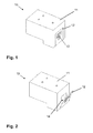
- FIGS. 1 to 4 An ink cartridge 10 for a printer (not shown) is shown, wherein the ink cartridge initially has a housing 11. Connected to the housing 11, or formed as part of the housing 11, is a contact transfer unit 12, which has a number of, in particular electrical, contacts 13. Via the contact transfer unit 12 and the contacts 13, data and information can be exchanged between the ink cartridge 10 and the printer in which the ink cartridge 10 is installed.
- the contact transfer unit 12 is connected to the housing 11 of the ink cartridge 10 in such a manner that the contact transfer unit 12 is folded and adhered in the final assembly of the contact transfer unit 12 to the ink cartridge 10.
- the contact transfer unit 12 advantageously closes a depression 14 within the housing 11.
- FIG. 4 shows an enlarged partial view FIG. 3 , what a FIG. 3 is marked with a circle and the reference symbol A.
- the control element 20 initially has a printed circuit board 21, via which the control element 20 is electronically connected to the contact transfer unit 12 of the ink cartridge 10.
- the control element 20 further has a microprocessor 22, for the operation of the control 20 further required electronic components 23 and a memory device 24 in which one or more cartridge identification numbers are stored.
- the controller 20 further includes means for transmitting at least one cartridge identification number to the printer, and means for changing at least one cartridge identification number. Through the controller 20, the cartridge identification numbers can be changed so that the cartridge in the printer, when a changed cartridge identification number is transmitted to the printer via the contact transfer unit 12, is identified as another one. This avoids bottlenecks in empties availability.
Landscapes
- Ink Jet (AREA)
Applications Claiming Priority (1)
| Application Number | Priority Date | Filing Date | Title |
|---|---|---|---|
| DE200820013962 DE202008013962U1 (de) | 2008-10-18 | 2008-10-18 | Steuerelement zur Konvertierung von Tintenpatronen |
Publications (1)
| Publication Number | Publication Date |
|---|---|
| EP2177362A1 true EP2177362A1 (fr) | 2010-04-21 |
Family
ID=40227437
Family Applications (1)
| Application Number | Title | Priority Date | Filing Date |
|---|---|---|---|
| EP09173117A Withdrawn EP2177362A1 (fr) | 2008-10-18 | 2009-10-15 | Elément de commande pour une cartouche d'encre et cartouche d'encre |
Country Status (2)
| Country | Link |
|---|---|
| EP (1) | EP2177362A1 (fr) |
| DE (1) | DE202008013962U1 (fr) |
Citations (6)
| Publication number | Priority date | Publication date | Assignee | Title |
|---|---|---|---|---|
| EP0903237A2 (fr) * | 1997-09-19 | 1999-03-24 | Xerox Corporation | Imprimante ayant un mode de service pour un matériau de marquage non-identifié |
| EP0916503A2 (fr) * | 1997-11-14 | 1999-05-19 | Canon Kabushiki Kaisha | Tête, appareil d'enregistrement possédant cette tête, méthode pour identifier la tête et méthode pour transmettre à la tête les informations d'identification |
| US20040036733A1 (en) * | 2000-06-16 | 2004-02-26 | Canon Kabushiki Kaisha | Solid semiconductor element, ink tank, ink jet recording apparatus provided with ink tank, liquid information acquiring method and liquid physical property change discriminating method |
| US6719397B1 (en) * | 2003-02-07 | 2004-04-13 | International United Technology Co., Ltd. | Ink jet printhead identification circuit and method |
| US20040125165A1 (en) * | 2002-12-30 | 2004-07-01 | Croley Donald Fred | Method and apparatus for generating and assigning a cartridge identification number to an imaging cartridge |
| EP1717042A2 (fr) * | 1998-11-26 | 2006-11-02 | Seiko Epson Corporation | Imprimante avec cartouche à encre associée |
-
2008
- 2008-10-18 DE DE200820013962 patent/DE202008013962U1/de not_active Expired - Lifetime
-
2009
- 2009-10-15 EP EP09173117A patent/EP2177362A1/fr not_active Withdrawn
Patent Citations (6)
| Publication number | Priority date | Publication date | Assignee | Title |
|---|---|---|---|---|
| EP0903237A2 (fr) * | 1997-09-19 | 1999-03-24 | Xerox Corporation | Imprimante ayant un mode de service pour un matériau de marquage non-identifié |
| EP0916503A2 (fr) * | 1997-11-14 | 1999-05-19 | Canon Kabushiki Kaisha | Tête, appareil d'enregistrement possédant cette tête, méthode pour identifier la tête et méthode pour transmettre à la tête les informations d'identification |
| EP1717042A2 (fr) * | 1998-11-26 | 2006-11-02 | Seiko Epson Corporation | Imprimante avec cartouche à encre associée |
| US20040036733A1 (en) * | 2000-06-16 | 2004-02-26 | Canon Kabushiki Kaisha | Solid semiconductor element, ink tank, ink jet recording apparatus provided with ink tank, liquid information acquiring method and liquid physical property change discriminating method |
| US20040125165A1 (en) * | 2002-12-30 | 2004-07-01 | Croley Donald Fred | Method and apparatus for generating and assigning a cartridge identification number to an imaging cartridge |
| US6719397B1 (en) * | 2003-02-07 | 2004-04-13 | International United Technology Co., Ltd. | Ink jet printhead identification circuit and method |
Also Published As
| Publication number | Publication date |
|---|---|
| DE202008013962U1 (de) | 2009-01-08 |
Similar Documents
| Publication | Publication Date | Title |
|---|---|---|
| DE2504627C2 (de) | Autonomes Datenverarbeitungsgerät | |
| DE69015792T2 (de) | Grundkarte mit Ausgleich. | |
| DE3126721A1 (de) | "datenverarbeitungsgeraet mit einem programmierbaren festspeicher" | |
| DE3127825A1 (de) | Kleine, tragbare datenverarbeitungsanordnung | |
| DE2646162B2 (de) | Schaltungsanordnung zum Ersetzen fehlerhafter Informationen in Speicherplätzen eines nicht veränderbaren Speichers | |
| DE10203856A1 (de) | Nachschlagtabelle-basierte USB-Identifizierung | |
| WO2002047215A1 (fr) | Appareil electrique | |
| DE102010007368A1 (de) | Chipresetter, Set mit einem solchen Chipresetter, Drucker mit einem solchen Chipresetter oder einem solchen Set und Verfahren zur Veränderung von Informationen auf dem Speicherchip einer Patrone eines Druckers | |
| DE3424241A1 (de) | Automatisiertes herstellungsverfahren fuer eine gedruckte schaltung bzw. leiterplatte und deren anwendungsbereich | |
| DE102009043642A1 (de) | Verfahren zum Bestücken von Leiterplatten mit Bauelementen | |
| DE102004034248A1 (de) | Elektronische Schaltung mit galvanisch getrennten Baugruppen | |
| EP0920683B1 (fr) | Procede de programmation d'un appareil electrique et carte a puce fontionnant comme interface | |
| EP0996084A2 (fr) | Dispositif pour imprimer sur un support | |
| EP2177362A1 (fr) | Elément de commande pour une cartouche d'encre et cartouche d'encre | |
| DE60128516T2 (de) | Verbidungsvorrichtung, Verbidungsverfahren und Speichermedium für die Aufzeichnung eines Computerlesbaresprogramms mit Verbidungsfunktionen | |
| EP0919385B1 (fr) | Recodage des têtes d'impression | |
| DE102009042653A1 (de) | Verfahren zum automatischen Bestücken von Substraten mit Bauelementen | |
| WO2001017328A1 (fr) | Procede et systeme destine a equiper des supports de circuits disposes dans une unite a equiper | |
| EP0464028B1 (fr) | Systeme multiprocesseurs | |
| DE102010023525B4 (de) | Datenspeicher-Stick zum Auslesen und Speichern von Daten eines Unterhaltungsspielgerätes | |
| DE2554425C3 (de) | Anordnung zum gegenseitigen Anpassen von Steuersignale austauschenden Geräten | |
| EP1716729B1 (fr) | Carte de circuit munie d'un lecteur de carte | |
| DE2442772A1 (de) | Steuergeraet fuer eingabe/ausgabeeinheiten einer datenverarbeitungsanlage | |
| WO2026041473A1 (fr) | Procédé mis en œuvre par ordinateur permettant de garantir la fabricabilité d'un produit électronique, procédé de fabrication de produits électroniques, système de préparation, dispositif de fabrication et programme informatique | |
| DE102014101162A1 (de) | Integrierter elektronischer Schaltkreis für ein Steuermodul zur Anbringung auf einer Verbrauchsmaterialkartusche, Steuermodul und Verbrauchsmaterialkartusche für einen Drucker |
Legal Events
| Date | Code | Title | Description |
|---|---|---|---|
| PUAI | Public reference made under article 153(3) epc to a published international application that has entered the european phase |
Free format text: ORIGINAL CODE: 0009012 |
|
| AK | Designated contracting states |
Kind code of ref document: A1 Designated state(s): AT BE BG CH CY CZ DE DK EE ES FI FR GB GR HR HU IE IS IT LI LT LU LV MC MK MT NL NO PL PT RO SE SI SK SM TR |
|
| STAA | Information on the status of an ep patent application or granted ep patent |
Free format text: STATUS: THE APPLICATION IS DEEMED TO BE WITHDRAWN |
|
| 18D | Application deemed to be withdrawn |
Effective date: 20101022 |