EP2177546A1 - Matiere de resine pour des objectifs optiques et element optique utilisant celle-ci - Google Patents
Matiere de resine pour des objectifs optiques et element optique utilisant celle-ci Download PDFInfo
- Publication number
- EP2177546A1 EP2177546A1 EP08792207A EP08792207A EP2177546A1 EP 2177546 A1 EP2177546 A1 EP 2177546A1 EP 08792207 A EP08792207 A EP 08792207A EP 08792207 A EP08792207 A EP 08792207A EP 2177546 A1 EP2177546 A1 EP 2177546A1
- Authority
- EP
- European Patent Office
- Prior art keywords
- refractive index
- inorganic particles
- optical
- resin
- light
- Prior art date
- Legal status (The legal status is an assumption and is not a legal conclusion. Google has not performed a legal analysis and makes no representation as to the accuracy of the status listed.)
- Withdrawn
Links
Images
Classifications
-
- C—CHEMISTRY; METALLURGY
- C08—ORGANIC MACROMOLECULAR COMPOUNDS; THEIR PREPARATION OR CHEMICAL WORKING-UP; COMPOSITIONS BASED THEREON
- C08F—MACROMOLECULAR COMPOUNDS OBTAINED BY REACTIONS ONLY INVOLVING CARBON-TO-CARBON UNSATURATED BONDS
- C08F2/00—Processes of polymerisation
- C08F2/44—Polymerisation in the presence of compounding ingredients, e.g. plasticisers, dyestuffs, fillers
-
- B—PERFORMING OPERATIONS; TRANSPORTING
- B82—NANOTECHNOLOGY
- B82Y—SPECIFIC USES OR APPLICATIONS OF NANOSTRUCTURES; MEASUREMENT OR ANALYSIS OF NANOSTRUCTURES; MANUFACTURE OR TREATMENT OF NANOSTRUCTURES
- B82Y30/00—Nanotechnology for materials or surface science, e.g. nanocomposites
-
- C—CHEMISTRY; METALLURGY
- C08—ORGANIC MACROMOLECULAR COMPOUNDS; THEIR PREPARATION OR CHEMICAL WORKING-UP; COMPOSITIONS BASED THEREON
- C08F—MACROMOLECULAR COMPOUNDS OBTAINED BY REACTIONS ONLY INVOLVING CARBON-TO-CARBON UNSATURATED BONDS
- C08F20/00—Homopolymers and copolymers of compounds having one or more unsaturated aliphatic radicals, each having only one carbon-to-carbon double bond, and only one being terminated by only one carboxyl radical or a salt, anhydride, ester, amide, imide or nitrile thereof
- C08F20/02—Monocarboxylic acids having less than ten carbon atoms, Derivatives thereof
- C08F20/10—Esters
- C08F20/12—Esters of monohydric alcohols or phenols
- C08F20/16—Esters of monohydric alcohols or phenols of phenols or of alcohols containing two or more carbon atoms
- C08F20/18—Esters of monohydric alcohols or phenols of phenols or of alcohols containing two or more carbon atoms with acrylic or methacrylic acids
-
- C—CHEMISTRY; METALLURGY
- C08—ORGANIC MACROMOLECULAR COMPOUNDS; THEIR PREPARATION OR CHEMICAL WORKING-UP; COMPOSITIONS BASED THEREON
- C08G—MACROMOLECULAR COMPOUNDS OBTAINED OTHERWISE THAN BY REACTIONS ONLY INVOLVING UNSATURATED CARBON-TO-CARBON BONDS
- C08G59/00—Polycondensates containing more than one epoxy group per molecule; Macromolecules obtained by polymerising compounds containing more than one epoxy group per molecule using curing agents or catalysts which react with the epoxy groups
- C08G59/18—Macromolecules obtained by polymerising compounds containing more than one epoxy group per molecule using curing agents or catalysts which react with the epoxy groups ; e.g. general methods of curing
- C08G59/20—Macromolecules obtained by polymerising compounds containing more than one epoxy group per molecule using curing agents or catalysts which react with the epoxy groups ; e.g. general methods of curing characterised by the epoxy compounds used
- C08G59/22—Di-epoxy compounds
- C08G59/24—Di-epoxy compounds carbocyclic
-
- C—CHEMISTRY; METALLURGY
- C08—ORGANIC MACROMOLECULAR COMPOUNDS; THEIR PREPARATION OR CHEMICAL WORKING-UP; COMPOSITIONS BASED THEREON
- C08K—Use of inorganic or non-macromolecular organic substances as compounding ingredients
- C08K9/00—Use of pretreated ingredients
- C08K9/04—Ingredients treated with organic substances
- C08K9/06—Ingredients treated with organic substances with silicon-containing compounds
-
- G—PHYSICS
- G02—OPTICS
- G02B—OPTICAL ELEMENTS, SYSTEMS OR APPARATUS
- G02B1/00—Optical elements characterised by the material of which they are made; Optical coatings for optical elements
- G02B1/04—Optical elements characterised by the material of which they are made; Optical coatings for optical elements made of organic materials, e.g. plastics
-
- G—PHYSICS
- G02—OPTICS
- G02B—OPTICAL ELEMENTS, SYSTEMS OR APPARATUS
- G02B27/00—Optical systems or apparatus not provided for by any of the groups G02B1/00 - G02B26/00, G02B30/00
- G02B27/10—Beam splitting or combining systems
- G02B27/14—Beam splitting or combining systems operating by reflection only
- G02B27/141—Beam splitting or combining systems operating by reflection only using dichroic mirrors
-
- G—PHYSICS
- G02—OPTICS
- G02B—OPTICAL ELEMENTS, SYSTEMS OR APPARATUS
- G02B27/00—Optical systems or apparatus not provided for by any of the groups G02B1/00 - G02B26/00, G02B30/00
- G02B27/10—Beam splitting or combining systems
- G02B27/14—Beam splitting or combining systems operating by reflection only
- G02B27/145—Beam splitting or combining systems operating by reflection only having sequential partially reflecting surfaces
- G02B27/146—Beam splitting or combining systems operating by reflection only having sequential partially reflecting surfaces with a tree or branched structure
-
- C—CHEMISTRY; METALLURGY
- C08—ORGANIC MACROMOLECULAR COMPOUNDS; THEIR PREPARATION OR CHEMICAL WORKING-UP; COMPOSITIONS BASED THEREON
- C08K—Use of inorganic or non-macromolecular organic substances as compounding ingredients
- C08K2201/00—Specific properties of additives
- C08K2201/002—Physical properties
-
- G—PHYSICS
- G11—INFORMATION STORAGE
- G11B—INFORMATION STORAGE BASED ON RELATIVE MOVEMENT BETWEEN RECORD CARRIER AND TRANSDUCER
- G11B7/00—Recording or reproducing by optical means, e.g. recording using a thermal beam of optical radiation by modifying optical properties or the physical structure, reproducing using an optical beam at lower power by sensing optical properties; Record carriers therefor
- G11B7/24—Record carriers characterised by shape, structure or physical properties, or by the selection of the material
- G11B7/241—Record carriers characterised by shape, structure or physical properties, or by the selection of the material characterised by the selection of the material
- G11B7/252—Record carriers characterised by shape, structure or physical properties, or by the selection of the material characterised by the selection of the material of layers other than recording layers
- G11B7/253—Record carriers characterised by shape, structure or physical properties, or by the selection of the material characterised by the selection of the material of layers other than recording layers of substrates
- G11B7/2533—Record carriers characterised by shape, structure or physical properties, or by the selection of the material characterised by the selection of the material of layers other than recording layers of substrates comprising resins
- G11B7/2538—Record carriers characterised by shape, structure or physical properties, or by the selection of the material characterised by the selection of the material of layers other than recording layers of substrates comprising resins polycycloolefins [PCO]
Definitions
- the present invention relates to a resin material which is suitably applied for a lens, a filter, a grating, an optical fiber and a planar light waveguide, and to an optical element using the same resin material.
- An optical pickup apparatus is installed in an information apparatus such as a player, a recorder or a drive for reading out or recording information from or to an optical information recording medium such as an MO, CD or DVD.
- the optical pickup apparatus has an optical element unit for irradiating light generated from a light source having a predetermined wavelength to the medium, and for receiving the reflected light by a light receiving element.
- the optical element unit is composed of an optical element containing a lens for condensing the light on the reflective layer of the optical information recording medium or on the light receiving element.
- thermosetting resin or a UV curable resin is a liquid at a normal temperature, and since it hardens by heat or UV light, it can be easily obtained the resin composite with required thermal properties, such as Tg after hardened.
- the optical pickup apparatus has a constitution capable of corresponding to the wavelength of the light to be applied to each of the media and the shape thereof.
- the optical element is preferably one commonly applicable to both of the optical information media from the viewpoint of cost and picking up property.
- the plastic material is a material having optical stability similar to that of a glass lens.
- the optical plastic material has a refractive index of sufficiently improved stability with respect to humidity, but the improvement in the thermal stability of the refractive index is not fully sufficient at the present stage.
- thermo-sensitivity containing synthetic microscopic material composed of a polymer host material having a thermosensitive property and microparticles dispersed in the polymer host material
- Patent documents 1 and 2 it is described that the thermo-sensitivity is decreased, for example, by mixing 40 weight% or more of particles of aluminium oxide or magnesium oxide in the host material.
- a refractive-index difference between the host material and inorganic particles are large, and the amount of mixed inorganic particles was so much that the decrease of light transmission was large and it was not able to use as an optical element.
- Patent document 3 there was proposed a high refractive-index resin composite which contains particles and a transparent resin, which has a refractive-index distribution of the particles in the depth direction the high refractive-index resin composite.
- the particles disclosed in Patent document 3 were easily aggregated to result in insufficient transparency, and sufficient restrain of thermo-sensitivity was not obtained.
- Patent document 4 was proposed an organic-inorganic composite material which contains a composite metal oxide nano particles composed of Si and other metallic element other than Si.
- a composite metal oxide nano particles composed of Si and other metallic element other than Si it was difficult to carry out the surface treatment of particles, and there was observed white turbidity seemingly caused by the layer separation between resin and particles. Furthermore, there was observed foaming from the particles at a high temperature state, and application as an optical resin was difficult.
- An object of the present invention is to provide an optical resin material which has high light transmittance and high thermal stability in refractive index, and to provide an optical element using the same resin material.
- the present invention can provide an optical resin material which has high light transmittance and high thermal stability in refractive index, and to provide an optical element using the same resin material.
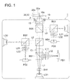
- Fig. 1 is a schematic drawing showing a composition of an optical pickup apparatus using an optical element of the present invention.
- an optical resin material comprising a curable resin and inorganic particles dispersed in the curable resin, provided that inorganic particles are the composed of two or more different metal oxides each having a different refractive index, wherein each of the inorganic particles has a distribution in a refractive index and is subjected to a surface treatment; at least a portion of a surface of each of the particles is modified with a surface modifier having a polymerizable functional group; and a refractive index nh of the curable resin after cured and a refractive index ng of the inorganic particle satisfy the predetermined condition.
- the curable resin used in the invention is a thermo-curable resin which is cured by heat treatment, a photocurable resin which is cured by irradiation with ultraviolet rays or electron beam. It may be used without specific limitation as long as the transparent resin composition is formed via curing process after mixing inorganic particles with an uncured curable resin.
- the curable resin preferably used are: an epoxy resin, a vinyl ester resin, and a silicone resin.
- the epoxy resin and its composition will be explained below, but the present invention is not specifically limited thereto.
- the curable resins applicable in the present invention include a hydrogenated epoxy resin, and an epoxy resin obtained via hydrogenation of an aromatic epoxy resin is preferably used.
- the hydrogenated epoxy resin include a hydrogenated epoxy resin obtained via hydrogenation of an aromatic ring of a bisphenol A type epoxy resin, a bisphenol F type epoxy resin, a bisphenol epoxy resin such as 3,3',5,5'-tetramethyl-4,4'-biphenol type epoxy resin or 4,4'-biphenol type epoxy resin, a phenol novolac type epoxy resin, a cresol novolac type epoxy resin, a bisphenol A novolac type epoxy resin, a naphthalene diol type epoxy resin, a trisphenylolmethane type epoxy resin, a tetrakisphenylolethane type epoxy resin, and a phenol dicyclopentadiene novolac type epoxy resin.
- a hydrogenated epoxy resin obtained via direct hydrogenation of the aromatic ring of a bisphenol A type epoxy resin, a bisphenol F type epoxy resin or a bisphenol epoxy resin is especially preferred in obtaining a hydrogenated epoxy resin with a high hydrogenation rate.
- An alicyclic epoxy resin obtained via epoxidation of alicyclic olefin can be added in an amount of 5 - 50 weight% in the hydrogenated epoxy resin.
- a specifically preferred alicyclic epoxy resin is 3,4-epoxycyclohexylmethyl-3',4'-epoxycyclohexane carboxylate. The viscosity of an epoxy resin composition containing this alicyclic epoxy resin can be reduced, which results in improvement of workability.
- a resin having a cyclic olefin structure is preferable among curable resins from the point of excelling in characteristics, such as transparency, heat resistivity, or low hygroscopic property.
- the cyclic structure are: a cyclic alkane structure (saturated alicyclic hydrocarbon, cycloalkane) and a cyclic olefin structure (unsaturated alicyclic hydrocarbon, cycloalkane).
- a preferable resin contains a cyclic olefin structure, it may be used resins disclosed, for example, in JP-A No. 2003-73559 , paragraphs numbers 0031 to 0036.
- an acid anhydride curing agent is added when an epoxy resin is used for a curable resin.
- a preferable acid anhydride curing agent has no carbon-carbon double bond in the molecule.
- examples thereof include hexahydrophthalic anhydride, methylhexahydrophthalic anhydride, hydrogenated nadic anhydride, hydrogenated methyl nadic anhydride, hydrogenated trialkyl hexahydrophthalic anhydride, and 2,4-diethylglutaric anhydride.
- hexahydrophthalic anhydride and/or methylhexahydrophthalic anhydride are especially preferred in providing excellent heat resistance and colorless cured materials.
- the addition amount of the acid anhydride curing agent depends on the epoxy equivalent in the epoxy resin, but it is preferably mixed in the range of 40 - 200 parts by weight based on 100 parts by weight of the epoxy resin.
- a curing accelerating agent may be added when an epoxy resin is used for a curable resin in order to promote curing reaction of the epoxy resin and the acid anhydride curing agent.
- the curing accelerating agent include tertiary amines and their salts, imidazoles and their salts, organic phosphine compounds, and organic acid metal salts such as zinc octylate or tin octylate.
- Specifically preferred curing accelerating agents are organic phosphine compounds.
- the addition amount of the curing accelerating agent is preferably in the range of 0.01 - 100 parts by weight based on 100 parts by weight of hydrogenated acid anhydride curing agent. The addition amount of the curing accelerating agent falling outside the above range is not preferable since balance between heat resistance and humidity resistance of the cured epoxy resin becomes lowered.
- the inorganic particles used in the present invention are composed of two or more kinds of metal oxide compounds each having a different refractive index and have a distribution in a refractive index. It can be arbitrary selected from inorganic particles enabling to achieve the object of the present invention.
- Inorganic particles having a distribution in a refractive index indicate the state that a single inorganic microparticle has a portion of a different refractive index.
- the local refractive index of one inorganic microparticle can be calculated from the information of the component composition of the inorganic microparticle obtained by means of a local elementary analysis using such as EDX in an observation with a transmission electron microscope (TEM).
- metal oxides it may be used metal oxides containing two or more kinds of metal selected from the group consisting of Li, Na, Mg, Al, Si, K, Ca, Sc, Ti, V, Cr, Mn, Fe, Co, Ni, Cu, Zn, Rb, Sr, Y, Nb, Zr, Mo, Ag, Cd, In, Sn, Sb, Cs, Ba, La, Ta, Hf, W, Ir, Tl, Pb, Bi and a rare earth metal.
- metal oxides containing two or more kinds of metal selected from the group consisting of Li, Na, Mg, Al, Si, K, Ca, Sc, Ti, V, Cr, Mn, Fe, Co, Ni, Cu, Zn, Rb, Sr, Y, Nb, Zr, Mo, Ag, Cd, In, Sn, Sb, Cs, Ba, La, Ta, Hf, W, Ir, Tl, Pb, Bi and a rare earth metal.
- oxide particles having a composition mixed with two or more kinds of oxides such as silicon oxide, titanium oxide, zinc oxide, aluminum oxide, zirconium oxide, hafnium oxide, niobium oxide, tantalum oxide, magnesium oxide, calcium oxide, strontium oxide, barium oxide, indium oxide, tin oxide or lead oxide.
- oxides such as silicon oxide, titanium oxide, zinc oxide, aluminum oxide, zirconium oxide, hafnium oxide, niobium oxide, tantalum oxide, magnesium oxide, calcium oxide, strontium oxide, barium oxide, indium oxide, tin oxide or lead oxide.
- the difference between the refractive index of the curable resin after being cured and the refractive index of the surface portion of the inorganic particles which touch the curable resin is small.
- the refractive index of the curable resin after being cured which can be chosen is often lower than the refractive index (the average refractive index) of the inorganic particles.
- the refractive index of the surface portion which touches the curable resin is lower than the refractive index of the inner portion of the inorganic particles.
- the inner portion of the inorganic particles refers to a central portion of the particle from the center to 10 to 90% of the diameters of a particle, and a surface portion refers to this outermost layer part.
- the local refractive indexes of the inner portion of the inorganic particles and the surface portion can be calculated from the information of the component composition of the inorganic microparticle obtained by means of a local element analysis using such as EDX in an observation with a transmission electron microscope (TEM).
- the light scattering at the time of pass through a light tends to be larger as the size of the inorganic particles are larger when the curable resin and the inorganic particles are dispersed. It was found that when the difference of the refractive index between the curable resin and the inorganic particles dispersed is small, the degree of light scattering produce by a light passed through becomes small even if relatively large sized inorganic particles are used. Moreover, it was found that transparency can be maintained even if the content of the inorganic particles is increased.
- the inorganic particles dispersed in the curable resin can be suitably chosen in consideration of the size of dn/dT of the inorganic particles itself, the difference between dn/dT of the inorganic particles and dn/dT of the curable resin, the refractive index of the inorganic particles according to the required properties for the optical resin material.
- the inorganic particles having high affinity with the curable resin used as a mother material i.e., having good dispersibility in the curable resin, which results in reduced light scattering in order to maintain a light transmittance state.
- inorganic particles applied are preferably compound oxide particles composed of silicon oxide and other oxides of Al, B, Ge, P, Ti, Nb, Zr, Y, W, La, Gd, and Ta.
- the above-mentioned refractive index is a value which is measured with inorganic particles following with ASTMD542 standard, and it is measured, for example, with an Abbe type refractometer.
- the refractive index values listed in various literatures can be used for it.
- the refractive index of inorganic particles can be checked by the following method: to prepare a dispersion of inorganic particles dispersed in various solvents having adjusted the refractive index; to measure the absorbance of the dispersion; and to measure the refractive index of the solvent which exhibits the minimum absorbance value.
- the inorganic particles composed of two or more kinds of metal oxides each having a different refractive index it is preferable to adjust the refractive index to fall in the above-mentioned range by compounding two or more kinds of metal oxides.
- two or more different kinds of metal atoms which exist in the inside of inorganic particles may exist uniformly, or they may be localized therein.
- the refractive index ng of the particles of two or more kinds of metal oxides having a different which refractive index with each other can be almost estimated from the volume fraction and a refractive index of each metal oxide.
- the particles composed of two or more kinds of metal oxides each having a different refractive index will exhibit almost the same optical property regardless the type of particles of the core-shell particles or uniformly dispersed particles when the diameter of the particle is 20 nm or less. Therefore, if the diameter of the particle in this range, it is preferable to locate an inorganic oxide having larger affinity with a surface modifying agent at an outer surface of the particles. In surface treatment, it is preferable to use the silane coupling agent from a heat-resistant viewpoint. In that case, the core shell type particles formed a silica surface are specifically effective. Further, it is preferable that the surface of the particles has a lower refractive index in order to reduce light scattering of the particles.
- inorganic particles having the refractive index in the above-describe range of 1.45 - 1.6 are preferable as inorganic particles which decrease the amount of
- a desirable effect is demonstrated by the obtained optical resin material having the refractive index in the range of 1.49 - 1.55.
- the inorganic particles in the present invention designate the inorganic particulates whose average grain diameters are 1 - 50 nm.
- An average grain diameter is preferably 1 - 20 nm, and more preferably it is 1 - 10 nm.
- An average grain diameter is a volume average value of the diameter (sphere conversion particle size) obtained by converting inorganic particulates into a sphere having the same volume of the inorganic particle.
- the shape of inorganic particles is not particularly limited, spherical inorganic particles are suitably used. Specifically, it is preferable that the value obtained by the following formula is 0.5 - 1.0, and more preferably n.7 - 1.0: the minimum diameter of the inorganic particles (it is the minimum value of the distance between two tangents when these two tangents are drawn to touch the outer periphery of the inorganic particles) / the maximum diameter of the inorganic particles (it is the maximum value of the distance between two tangents when these two tangents are drawn to touch the outer periphery of the inorganic particles).
- inorganic particles with a relatively narrow distribution are suitably used rather than inorganic particles with a wide distribution.
- any known methods can be applied for producing the inorganic particles without any limitations.
- the production method include: a mechanical method (a method of pulverizing a massive compound material with a pulverizing device such as a ball mill or Attritor), a pyrolysis method (a method to obtain particles by thermally decomposing the raw material), a spray drying method, a flame spraying method, a plasma method, a gas phase reaction method, freeze drying method, a heat kerosene method, a heat petroleum method, a precipitation method (a co-precipitation method), a hydrolysis method (an aqueous salt solution method, an alkoxide method and a sol-gel method) and a hydrothermal method (a precipitation method, a crystallization method, a hydrothermal decomposition method, a hydrothermal decomposition method and a hydrothermal oxidation methods).
- a mechanical method a method of pulverizing a massive compound material with a pulverizing device such as a ball
- required inorganic particles can be obtained by hydrolyzing a plurality of halogenated metals and alkoxy metals as raw materials in the reaction system containing water using.
- the way of using together an organic acid or organic amine is also used for stabilizing the inorganic particles.
- the required oxide particles can be obtained by applying a frequently employed method for forming inorganic particles (oxide particles), in which a metal powder of a suitable amount for forming dust cloud is thrown into a chemical flame and burned in an oxygen containing atmosphere to produce oxide particles having a size of 5 - 100 nm.
- the required oxide particles can also be obtained in a gas phase by the reaction of a raw material gas flow and an oxygen gas as disclosed in JP-A No. 2005-218937 .
- any known methods can be applied for the surface modification without any limitation.
- a method can be applied in which the surface of each particle is modified by hydrolysis of the modifier agent in the presence of water.
- an acid or an alkali is suitably applied as a catalyst. It is generally considered that a hydroxyl group at the surface of the particle and a hydroxyl group formed by hydrolysis of the modifier agent are combined to form a bond by dehydration.
- inorganic particles are subjected to a surface treatment.
- Methods to treat the surface of the inorganic particles include a surface treatment by a surface modifier such as a coupling agent, and a surface treatment by polymer grafting or mechanochemical processing.
- Examples of the surface modifier used for surface treatment of inorganic particles include an organic silane compound such as a silane type coupling agent, silicone oil, and coupling agents of a titanate type, an aluminate type or a zirconate type. These are not specifically limited, however, it can be appropriately selected depending on the type of inorganic particles and a thermoplastic resin in which the inorganic particles are dispersed. Further, two or more different surface treatments can be simultaneously or separately performed.
- an organic silane compound such as a silane type coupling agent, silicone oil, and coupling agents of a titanate type, an aluminate type or a zirconate type.
- silane type surface treating agent examples include vinylsilazane, trimethylchlorosilane, dimethyldichlorosilane, methyltrichlorosilane, trimethylalkoxysilane, dimethyldialkoxysilane, methyltrialkoxysilane and hexamethyldisilazane.
- vinylsilazane trimethylchlorosilane, dimethyldichlorosilane, methyltrichlorosilane, trimethylalkoxysilane, dimethyldialkoxysilane, methyltrialkoxysilane and hexamethyldisilazane.
- trimethylmethoxysilane, dimethyldimethoxysilane, methyltrimethoxysilane and hexamethyldisilazane are preferably utilized.
- silicone oil type surface treating agent examples include straight silicone oil such as dimethylsilicone oil, methylphenylsilicone oil or methylhydrogensilicone oil; and modified silicone oil such as amino modified silicone oil, epoxy modified silicone oil, carboxyl modified silicone oil, carbinol modified silicone oil, methacryl modified silicone oil, mercapto modified silicone oil, phenol modified silicon oil, one terminal reactive modified silicone oil, different functional group modified silicone oil, polyether modified silicone oil, methylstyryl modified silicone oil, alkyl modified silicone oil, higher fatty acid ester modified silicone oil, hydrophilic specific modified silicone oil, higher alkoxy modified silicone oil, higher fatty acid containing modified silicone oil or fluorine modified silicone oil.
- straight silicone oil such as dimethylsilicone oil, methylphenylsilicone oil or methylhydrogensilicone oil
- modified silicone oil such as amino modified silicone oil, epoxy modified silicone oil, carboxyl modified silicone oil, carbinol modified silicone oil, methacryl modified silicone oil, mercapto modified silicone oil, phenol modified silicon
- a surface treating agent having a polymerizable functional group the following compounds are commercially available and it can be arbitrary selected: vinyltrichlorosilane, vinyltrimethoxysilane, vinyltriethoxysilane, 2-(3, 4-epoxycyclohexyl)ethyltrimethoxysilane, 3-xyglycidoxypropyltrimethoxysilane, 3-glycidoxypropylmethyldiethoxysilane, 3-glycidoxypropyltriethoxysilane, p-styryltrimethoxysilane, 3-methacryloxypropylmethyldimethoxysilane, 3-methacryloxypropyltriethoxysilane and 3-acryloxypropyl trimethoxysilane.
- These treating agents may be appropriately diluted with hexane, toluene, methanol, ethanol, acetone or water before use.
- Examples of a surface treatment method employing a surface modifying agent include a wet heating method, a wet filtering method, a dry stirring method, an integral blend method and a granulating method.
- a dry stirring method is preferably employed so as to prevent particle aggregation, however, the method surface treatment is not limited thereto.
- surface modifying agents may be utilized in combination of plural kinds thereof. Further, since characteristics of surface modified particles may differ depending on kinds of a surface modifying agent used, the surface modifying agent can be selected to improve the affinity to a thermoplastic resin to be utilized when an optical resin material is prepared.
- the content of the surface modifying agent is not specifically limited, however, it is required to use a surface modifying agent having a polymerizable functional group un the molecule, and it is preferable that the content is from 1 to 40% by weight, and more preferably from 10 to 30% by weight, based on the weight of inorganic particles.
- the optical element of the present invention is characterized by using the above-mentioned resin material for optical use.
- the production method of an optical element is described in detail.
- melt molding method As a melt molding method, a press forming method, an extrusion molding method and an injection molding method can be cited. However, an injection molding method is preferable from a viewpoint of moldability and manufacturing efficiency.
- Molding conditions are suitably chosen by the application purpose or the forming method.
- the temperature of the resin composite (there are two cases, one is a case in which a resin is used solely and another is a case in which a mixture of a resin and an additive are used) in injection molding method is determined by considering the followings.
- the temperature is preferably in the range of 150-400 °C, it is more preferably from 200-350 °C, and it is still more preferably from 200-330 °C.
- the molded product of the present invention can be utilized in various forms such as a spherical form, a bar form, a plate form, a column form, a cylinder form, a tube form, a fiber form, or a film or sheet form. It is applied to an optical plastic lens which is one of various optical elements of the present invention since it is excellent in low birefringence, transparency, mechanical strength, heat resistance and low water absorption. It can be suitably applied to other optical devices.
- optical resin material of the present invention is obtained by the above-described preparation method. The specific application thereof to optical elements will be described.
- an optical lens and an optical prism incorporated in an image pick lens system of a camera; a lens of a microscope, an endoscope and a telescope; an light transmitting lens such as an eyeglass lens; a pickup lens for an optical disk such as CD, CD-ROM, WORM (recordable optical disk), MO (rewritable optical disk; magneto-optical disk), MD (mini-disk) and DVD (digital versatile disk); and a lens in a laser scanning system such as an f ⁇ lens for a laser beam printer or a lens for a sensor; and a prism lens in a finder system of a camera.
- optical disk examples include: CD, CD-ROM, WORM (recordable optical disk), MO (rewritable optical disk; magneto-optical disk), MD (mini-disk) and DVD (digital versatile disk).
- a light guide of a liquid crystal display and the like an optical film such as a polarizer film, a retardation film or a light scattering film; a light diffusion plate; an optical card; or a liquid crystal display element substrate.
- the molded products are preferably used as an optical element such as a pickup lens or a laser scanning system lens, in which birefringence is required.
- an optical element such as a pickup lens or a laser scanning system lens, in which birefringence is required.
- Most preferable application is a pickup lens.
- the optical resin material of the present invention has an excellent thermal properties and it is suitably applied for a lens for a high density optical disk using a blue-violet laser beam.
- a pickup lens which is required to exhibit low birefringence
- an optical element used for a lens system of laser scanning system.
- An optical pickup apparatus 1 is described below by referring figure in which is used an optical element molded by the optical resin material of the present invention.
- the optical pickup apparatus 1 of an embodiment of the present invention has three kinds of semiconductor laser oscillator LD1, LD2 and LD3 as the light sources.
- the semiconductor laser oscillator LD1 emits a light beam of a specific wavelength within the range of from 350 to 450 nm (405 nm or 407 nm, for example) for a BD (or AOD) 10.
- the semiconductor laser oscillator LD2 emits a light beam of a specific wavelength within the range of from 620 to 680 nm for a DVD 20.
- the semiconductor laser oscillator LD3 emits a light beam of a specific wavelength within the range of from 750 to 810 nm for a CD 30.
- a shaver SH1, a splitter BS1, a collimator CL, splitters BS4 and BS5, and a objective lens 15 are successively arranged in line in the direction of the light axis of the blue light beam emitted from the semiconductor laser oscillator LD1, namely in the direction from the bottom to the top of the drawing, and the DB10, DVD 20 or CD 30 as the optical information recording medium is placed at a position facing to the objective lens 15. Further, a cylindrical lens L11, a concave lens L12 and a photo-detector PD1 are successively arranged in line on the right side of the splitter BS1 in Fig. 1 .
- Splitters BS2 and BS4 are successively arranged in line in the direction of the light axis of red light beam emitted from the semiconductor laser oscillator LD2, namely in the direction of left to right in Fig. 1 . Further, a cylindrical lens L21, a concave lens L22 and a photo-detector PD2 are successively arranged under the splitter BS2 in Fig. 1 .
- Splitters BS3 and BS5 are successively arranged in line in the direction of the light axis of light beam emitted from the semiconductor laser oscillator LD3, namely in the direction of right to left in Fig. 1 . Further, a cylindrical lens L31, a concave lens L32 and a photo-detector PD3 are successively arranged under the splitter BS3 in Fig. 1 .
- the objective lens 15, which is an optical element, is arranged so as to face to the BD 10, DVD 20 or CD 30 as the optical information recording medium, and has the function of condensing the light emitted from each of the semiconductor laser oscillator LD-1, LD2 and LD3 to the BD 10, DVD 20 or CD 30.
- a two dimensional actuator 2 is attached to the objective lens 15 so that the objective lens 15 can be freely moved in the upward and downward direction in Fig. 1 by the two dimensional actuator.
- the optical pickup apparatus 1 of the present invention takes a different action according to the kind of a recording medium. Therefore, the details of the actions for BD10, DVD20 and CD30 will be respectively described.
- the semiconductor laser oscillator LD1. emits light.
- the emitted light is formed light beam L1 illustrated by the solid line in Fig. 1 , the light beam is corrected in the shape by passing through the shaver SH1, passed through the splitter SB1 and then made to parallel light by the collimator CL, and further by passing through the splitters BS4, SB5 and the objective lens 15 to form a light spot on the recording surface of 10a of the BD 10.
- the light forming the light spot is modulated by the information bits on the recording surface 10a of BD 10 and reflected by the surface 10a, the reflected light is passed through the objective lens 15, splitter BS5 and collimator CL, and then reflected by the splitter BS1 and passed trough the cylindrical lens L11 to be given astigmatic focus error. After that, the light is passed through the concave lens L12 and received by the photo-detector PD1.
- recording the information to the BD 10 or playback of the information in the BD 10 can be performed.
- the semiconductor laser oscillator LD2 When information is recorded to the DVD 20 or when information is played back from the DVD 20, the semiconductor laser oscillator LD2 emits light.
- the emitted light is formed light beam L2 illustrated by the chain line in Fig. 1 , the light beam is passed through the splitter SB2 and reflected by the splitter BS4. After that the light is passed through the splitter SB5 and the objective lens 15 to form a light spot on the recording surface 20a of the DVD 20.
- the light forming the light spot is modulated by the information bits on the recording surface 20a of DVD 20 and reflected by the surface 20a, the reflected light is passed through the objective lens 15 and splitter BS5, reflected by the splitters BS4 and BS2, and passed trough the cylindrical lens L21 to be given astigmatic focus error. After that, the light is passed through the concave lens L22 and received by the photo-detector PD2.
- the recording of the information to the DVD 20 or playback of the information in the DVD 20 can be performed.
- the semiconductor laser oscillator LD3 When information is recorded to the CD 30 or when information is played back from the CD 30, the semiconductor laser oscillator LD3 emits light.
- the emitted light is formed light beam L3 illustrated by the broken line in Fig. 1 , the light beam is passed through the splitter SB3 and reflected by the splitter BS5. After that the light is passed through the objective lens 15 to form a light spot on the recording surface 30a of the CD 30.
- the light forming the light spot is modulated by the information bits on the recording surface 30a of CD 30 and reflected by the surface 30a, the reflected light is passed through the objective lens 15 and reflected by the splitters BS5 and BS3, and passed trough the cylindrical lens L31 to be given astigmatic focus error. After that, the light is passed through the concave lens L32 and received by the photo-detector PD3.
- recording the information to the CD 30 or playback of the information in the CD 30 can be performed.
- the optical pickup apparatus 1 detects the light amount variation caused by the variation in the shape and the position of the light spot on the each of the photo-detectors PD 1, PD2 and PD 3 for focusing and track detecting.
- the objective lens 15 is moved by the two dimensional actuator 2 according to the detecting result by the each of the photo-detector PD1, PD2 and PD3 so that the light from the semiconductor laser oscillator LD1, LD2 or LD3 is focused on the designated track on the recording surface 10a, 20a or 30a of the BD10, DVD 20 or CD 30, respectively.
- Nano Creator TM produced by Hosokawa Micron Corp.
- an oxygen gas were introduced in a reaction space and they were allowed to react to yield inorganic particles in the form of white powder.
- the inorganic particles were subjected to a surface modification treatment. More specifically, 300 g of methanol and 1 mol% of aqueous nitric acid were added to 5 g of the obtained inorganic particles. While this solution was stirred at 50 °C, 100 g of methanol and 6 g of cyclopentyltrimethoxysilane were added in it for 60 minutes, and 3 g of vinylmethoxysilane was further added and the mixture was stirred for 24 hours. Moreover, the obtained transparent dispersion was suspended in ethyl acetate, and a centrifuge separation was carried out to obtain inorganic particles 1.
- Inorganic particles 1 were confirmed to have a core-shell structure composed of a TiO 2 core and a SiO 2 shell by an observation with a transmission electron microscope (TEM) and by a local elementary analysis of EDX, and the refractive index of the inner portion of inorganic particles 1 was found to be 2.7 and the surface portion thereof was found to be 1.48.
- TEM transmission electron microscope
- Inorganic particles 2 in the form of white powder were prepared in the same manner as preparation of inorganic particles 1 except that a surface modification treatment was not carried out.
- Inorganic particles 2 were confirmed to have a core-shell structure composed of a TiO 2 core and a SiO 2 shell by an observation with a transmission electron microscope (TEM) and by a local elementary analysis of EDX, and the refractive index of the inner portion of inorganic particles 2 was found to be 2.7 and the surface portion thereof was found to be 1.48.
- TEM transmission electron microscope
- Inorganic particles 3 were confirmed to have a core-shell structure composed of a TiO 2 core and a SiO 2 shell by an observation with a transmission electron microscope (TEM) and by a local elementary analysis of EDX, and the refractive index of the inner portion of inorganic particles 3 was found to be 2.7 and the surface portion thereof was found to be 1.48.
- TEM transmission electron microscope
- Inorganic particles 4 were confirmed to have a structure in which TiO 2 was dispersed in SiO 2 by an observation with a transmission electron microscope (TEM) and by a local elementary analysis of EDX, and the refractive index of the inner portion and the surface portion of inorganic particles 4 were found to be 1.49.
- TEM transmission electron microscope
- a suspension was prepared by adding 10 g of Aluminum Oxide C (produced by Nippon Aerosil Co., Ltd.) to a mixture solution of 160 ml of pure water, 560 ml of ethanol and 30 ml of aqueous ammonia solution (25%). To the suspension was added 4 ml of LS-2430 followed by dispersing with Ultra Apex Mill (produced by Kotobuki Co., Ltd.) to obtain a dispersion of alumina particles.
- Aluminum Oxide C produced by Nippon Aerosil Co., Ltd.
- Inorganic particles 5 were confirmed to have a core-shell structure composed of a Al 2 O 3 core and a SiO 2 shell by an observation with a transmission electron microscope (TEM) and by a local elementary analysis of EDX, and the refractive index of the inner portion of inorganic particles 5 was found to be 1.8 and the surface portion thereof was found to be 1.48.
- TEM transmission electron microscope
- Inorganic particles 6 were confirmed to have a core-shell structure composed of a ZrO 2 core and a SiO 2 shell by an observation with a transmission electron microscope (TEM) and by a local elementary analysis of EDX, and the refractive index of the inner portion of inorganic particles 6 was found to be 2.2 and the surface portion thereof was found to be 1.48.
- TEM transmission electron microscope
- Aluminum Oxide C (aluminium oxide, produced by Nippon Aerosil Co., Ltd.) were applied and they were designated as inorganic particles 7.
- the prepared inorganic particles were subjected to measurements of average particle size and refractive index using the method described below.
- Table 1 Inorganic Particles No. Composition Surface Treatment Average Particle Size (nm) Refractive Index Core Shell ng Inner Portion Surface Portion 1 TiO 2 SiO 2 Yes 110 1.57 2.70 1.48 2 TiO 2 SiO 2 None 115 1.62 2.70 1.48 3 TiO 2 SiO 2 Yes 115 1.62 2.70 1.48 4 TiO 2 is dispersed in SiO 2 Yes 25 1.49 1.49 1.49 5 Al 2 O 3 SiO 2 Yes 20 1.51 1.70 1.48 6 ZrO 2 SiO 2 Yes 25 1.55 2.18 1.48 7 Homogeneous Al 2 O 3 None 13 1.70 1.70 1.70
- thermo-curable resin There were mixed 39 g of 1-adamantyl methacyrate as a thermo-curable resin, 23 g of the above-described inorganic particles 1 as inorganic particles, 0.1 g of Irganox 1010 TM as an anti-oxidation agent and 0.05 g of 1,1-bis(t-butylperaxy)-3,3,5-trimethylcyclohexane (Perhexa 3M-95, produced by NOF Corporation) as a radical polymerization initiator. After completion of mixing, the mixture was kneaded with PolyLab Mixer (HAAKE Co, Ltd.) at a rotation speed of 10 rpm for 10 minutes to obtain a resin composition.
- PolyLab Mixer HAAKE Co, Ltd.
- the tabular optical resin material 1 (plate for an examination) was produced by carrying out a heating press at 110 °C for 1 hour.
- Optical resin materials 2 - 7 were prepared in the same manner as preparation of optical resin material 1, except that inorganic particles 1 was replaced by each of inorganic particles 2 - 7.
- the transmittance of each sample was measured by a method according to ASTM D1003. Specifically, a light transmittance was measured using TURBIDITY METER T-2600DA, (manufactured by Tokyo Denshoku Co., Ltd.), and thus measured light transmittance was referred to as transmittance of a sample.
- the sample exhibiting transmittance of 80% or less was judged as not suitable for the optical element since the transparency was not sufficient.
- An optical resin material was prepared in the same manner as preparation of optical resin material 1, except that inorganic particles 1 was not added. After heat-melting the prepared optical resin material, it was molded in the form of a plate having a thickness of 3 mm. This plate was polished. While changing temperature from 23 °C to 60 °C and measuring the refractive index at each temperature with a light of 588 nm using the automatic refractometer (KPR-200, manufactured by Kalnew Optical Industrial Co., Ltd.), the temperature change rate (dn/dT of the resin) of the refractive index accompanying the temperature change was calculated.
- KPR-200 automatic refractometer
- optical resin materials 1 - 7 each containing one of inorganic particles 1 - 7 were heat-melted, followed by molded in the form of a plate having a thickness of 3 mm. While changing temperature from 23 °C to 60 °C and measuring the refractive index at each temperature with a light of 588 nm, the temperature change rate (dn/dT of the resin) of the refractive index accompanying the temperature change was calculated.
- dn/dT rate of change of each sample was calculated via the following equation, and these values were used as an indicator of the temperature stability of a refractive index.
- dn / dT rate of change % dn / dT of the resin - dn / dT of each sample / dn / dT of the resin x 100
- the samples of the present invention are demonstrated to exhibit a high light transmission and a high temperature stability of refractive index.
Landscapes
- Chemical & Material Sciences (AREA)
- Physics & Mathematics (AREA)
- Chemical Kinetics & Catalysis (AREA)
- Medicinal Chemistry (AREA)
- Polymers & Plastics (AREA)
- Organic Chemistry (AREA)
- Health & Medical Sciences (AREA)
- General Physics & Mathematics (AREA)
- Engineering & Computer Science (AREA)
- Optics & Photonics (AREA)
- Nanotechnology (AREA)
- Composite Materials (AREA)
- Crystallography & Structural Chemistry (AREA)
- Materials Engineering (AREA)
- Condensed Matter Physics & Semiconductors (AREA)
- Compositions Of Macromolecular Compounds (AREA)
- Eyeglasses (AREA)
Applications Claiming Priority (2)
| Application Number | Priority Date | Filing Date | Title |
|---|---|---|---|
| JP2007207804 | 2007-08-09 | ||
| PCT/JP2008/064021 WO2009020116A1 (fr) | 2007-08-09 | 2008-08-05 | Matiere de resine pour des objectifs optiques et element optique utilisant celle-ci |
Publications (2)
| Publication Number | Publication Date |
|---|---|
| EP2177546A1 true EP2177546A1 (fr) | 2010-04-21 |
| EP2177546A4 EP2177546A4 (fr) | 2012-02-29 |
Family
ID=40341348
Family Applications (1)
| Application Number | Title | Priority Date | Filing Date |
|---|---|---|---|
| EP08792207A Withdrawn EP2177546A4 (fr) | 2007-08-09 | 2008-08-05 | Matiere de resine pour des objectifs optiques et element optique utilisant celle-ci |
Country Status (6)
| Country | Link |
|---|---|
| US (1) | US20100190919A1 (fr) |
| EP (1) | EP2177546A4 (fr) |
| JP (1) | JPWO2009020116A1 (fr) |
| KR (1) | KR20100056452A (fr) |
| CN (1) | CN101772521A (fr) |
| WO (1) | WO2009020116A1 (fr) |
Cited By (1)
| Publication number | Priority date | Publication date | Assignee | Title |
|---|---|---|---|---|
| WO2016027193A1 (fr) * | 2014-08-19 | 2016-02-25 | Nova Chemicals (International) S.A. | Copolymères d'éthylène produits à l'aide de catalyseur à site unique |
Families Citing this family (13)
| Publication number | Priority date | Publication date | Assignee | Title |
|---|---|---|---|---|
| CN101831129A (zh) * | 2010-03-31 | 2010-09-15 | 江苏华天通科技有限公司 | 含过渡金属氧化物纳米材料的电焊用透镜的制备方法 |
| JP2014062198A (ja) * | 2012-09-21 | 2014-04-10 | Dow Corning Toray Co Ltd | 硬化性シリコーン組成物、それを用いてなる半導体封止材および光半導体装置 |
| WO2014132624A1 (fr) * | 2013-02-27 | 2014-09-04 | パナソニック株式会社 | Matériau optique, élément optique, et élément optique composite |
| US10329460B2 (en) * | 2016-09-14 | 2019-06-25 | 3M Innovative Properties Company | Fast curing optical adhesive |
| US11529230B2 (en) | 2019-04-05 | 2022-12-20 | Amo Groningen B.V. | Systems and methods for correcting power of an intraocular lens using refractive index writing |
| US11944574B2 (en) | 2019-04-05 | 2024-04-02 | Amo Groningen B.V. | Systems and methods for multiple layer intraocular lens and using refractive index writing |
| US11583388B2 (en) | 2019-04-05 | 2023-02-21 | Amo Groningen B.V. | Systems and methods for spectacle independence using refractive index writing with an intraocular lens |
| US11564839B2 (en) | 2019-04-05 | 2023-01-31 | Amo Groningen B.V. | Systems and methods for vergence matching of an intraocular lens with refractive index writing |
| US11583389B2 (en) | 2019-04-05 | 2023-02-21 | Amo Groningen B.V. | Systems and methods for correcting photic phenomenon from an intraocular lens and using refractive index writing |
| US12377622B2 (en) | 2019-04-05 | 2025-08-05 | Amo Groningen B.V. | Systems and methods for vergence matching with an optical profile and using refractive index writing |
| US12357509B2 (en) | 2019-04-05 | 2025-07-15 | Amo Groningen B.V. | Systems and methods for improving vision from an intraocular lens in an incorrect position and using refractive index writing |
| US11678975B2 (en) | 2019-04-05 | 2023-06-20 | Amo Groningen B.V. | Systems and methods for treating ocular disease with an intraocular lens and refractive index writing |
| CN114634357A (zh) * | 2022-03-03 | 2022-06-17 | 佛山仙湖实验室 | 一种光固化3d打印陶瓷复合材料及其制备方法与应用 |
Family Cites Families (14)
| Publication number | Priority date | Publication date | Assignee | Title |
|---|---|---|---|---|
| JPS5277154A (en) * | 1975-12-24 | 1977-06-29 | Seiko Epson Corp | Transparent palstic molded articles |
| US6518353B2 (en) | 2000-12-22 | 2003-02-11 | Eastman Kodal Company | Reduced temperature sensitive polymeric optical article and method of making same |
| JP4485717B2 (ja) | 2001-09-04 | 2010-06-23 | 三井化学株式会社 | 熱可塑性材料組成物、及びそれを含んで構成される光学部品 |
| JP4485716B2 (ja) * | 2001-09-04 | 2010-06-23 | 三井化学株式会社 | 熱可塑性材料組成物、及びそれを含んで構成される光学部品 |
| US6642295B2 (en) | 2001-12-21 | 2003-11-04 | Eastman Kodak Company | Photoresist nanocomposite optical plastic article and method of making same |
| JP2004292698A (ja) * | 2003-03-27 | 2004-10-21 | Nissan Motor Co Ltd | 樹脂組成物、充填材及び樹脂組成物の製造方法 |
| JP2005146042A (ja) | 2003-11-12 | 2005-06-09 | Olympus Corp | 有機無機複合材料及びその製造方法並びに光学素子 |
| JP2005213410A (ja) | 2004-01-30 | 2005-08-11 | Nippon Zeon Co Ltd | 高屈折率樹脂組成物 |
| JP4420690B2 (ja) | 2004-02-04 | 2010-02-24 | ホソカワミクロン株式会社 | 微粒子製造方法及び微粒子製造装置 |
| JP2005325349A (ja) * | 2004-04-16 | 2005-11-24 | Konica Minolta Opto Inc | 熱可塑性樹脂材料及びそれを用いた光学素子 |
| JP2007077235A (ja) * | 2005-09-13 | 2007-03-29 | Konica Minolta Opto Inc | 熱可塑性樹脂組成物及び光学素子 |
| JP2007154159A (ja) * | 2005-11-09 | 2007-06-21 | Konica Minolta Opto Inc | 有機無機複合材料及び光学素子 |
| WO2007116803A1 (fr) * | 2006-04-07 | 2007-10-18 | Konica Minolta Opto, Inc. | Materiau composite organique/inorganique optique et element optique |
| JP4315195B2 (ja) * | 2006-12-21 | 2009-08-19 | ソニー株式会社 | 硬化性樹脂材料−微粒子複合材料及びその製造方法、光学材料、並びに発光装置 |
-
2008
- 2008-08-05 WO PCT/JP2008/064021 patent/WO2009020116A1/fr not_active Ceased
- 2008-08-05 KR KR1020107002630A patent/KR20100056452A/ko not_active Withdrawn
- 2008-08-05 CN CN200880102097A patent/CN101772521A/zh active Pending
- 2008-08-05 EP EP08792207A patent/EP2177546A4/fr not_active Withdrawn
- 2008-08-05 US US12/668,457 patent/US20100190919A1/en not_active Abandoned
- 2008-08-05 JP JP2009526460A patent/JPWO2009020116A1/ja active Pending
Cited By (5)
| Publication number | Priority date | Publication date | Assignee | Title |
|---|---|---|---|---|
| WO2016027193A1 (fr) * | 2014-08-19 | 2016-02-25 | Nova Chemicals (International) S.A. | Copolymères d'éthylène produits à l'aide de catalyseur à site unique |
| CN106661155A (zh) * | 2014-08-19 | 2017-05-10 | 诺瓦化学品(国际)股份有限公司 | 用单位点催化剂制备的乙烯共聚物 |
| US10239976B2 (en) | 2014-08-19 | 2019-03-26 | Nova Chemicals (International) S.A. | Ethylene copolymers produced with single site catalyst |
| CN106661155B (zh) * | 2014-08-19 | 2021-05-28 | 诺瓦化学品(国际)股份有限公司 | 用单位点催化剂制备的乙烯共聚物 |
| US11053332B2 (en) | 2014-08-19 | 2021-07-06 | Nova Chemicals (International) S.A. | Ethylene copolymers produced with single site catalyst |
Also Published As
| Publication number | Publication date |
|---|---|
| CN101772521A (zh) | 2010-07-07 |
| EP2177546A4 (fr) | 2012-02-29 |
| JPWO2009020116A1 (ja) | 2010-11-04 |
| US20100190919A1 (en) | 2010-07-29 |
| KR20100056452A (ko) | 2010-05-27 |
| WO2009020116A1 (fr) | 2009-02-12 |
Similar Documents
| Publication | Publication Date | Title |
|---|---|---|
| EP2177546A1 (fr) | Matiere de resine pour des objectifs optiques et element optique utilisant celle-ci | |
| JPWO2009025127A1 (ja) | 光学用樹脂材料及び光学素子 | |
| JP2008001895A (ja) | 光学用樹脂材料及び光学素子 | |
| JP5163640B2 (ja) | 光学用有機無機複合材料及び光学素子 | |
| WO2008044342A1 (fr) | Matériau composite organique/inorganique et élément optique | |
| WO2008065862A1 (fr) | Matériau de dispositif optique en matière plastique, dispositif optique en matière plastique fait à partir de celui-ci et dispositif de capture optique | |
| JP2009013009A (ja) | 無機微粒子粉体の製造方法、有機無機複合材料及び光学素子 | |
| JP2010043191A (ja) | 光学部品およびプラスチックレンズ | |
| JP2008280443A (ja) | 複合樹脂材料の製造方法、複合樹脂材料、及び光学素子 | |
| JP2007154159A (ja) | 有機無機複合材料及び光学素子 | |
| JP5119850B2 (ja) | 複合樹脂組成物の製造方法 | |
| JP2009221350A (ja) | 樹脂組成物、その製造方法、及びそれを用いた光学素子 | |
| JP2007163655A (ja) | 光学用樹脂材料及び光学素子 | |
| JP2007077235A (ja) | 熱可塑性樹脂組成物及び光学素子 | |
| JP5277457B2 (ja) | 複合金属酸化物微粒子含有樹脂材料の製造方法、及びそれを用いた光学素子 | |
| JP2009235325A (ja) | 光学用樹脂材料の製造方法、光学用樹脂材料、及び光学素子 | |
| JP2007231237A (ja) | 有機無機複合材料及び光学素子並びに有機無機複合材料の製造方法 | |
| JP2007254681A (ja) | 熱可塑性複合材料及び光学素子 | |
| JP2007154026A (ja) | 光学用樹脂材料の製造方法及び光学素子 | |
| JP2008074635A (ja) | コアシェル型酸化ケイ素粒子とその製造方法、それを用いた無機微粒子分散樹脂組成物及び光学素子 | |
| JP2007264581A (ja) | 光学用無機材料の製造方法並びに光学用無機材料、光学用樹脂材料及び光学素子 | |
| JP2007161980A (ja) | マスターバッチ、光学素子、マスターバッチの製造方法及び光学素子の製造方法 | |
| JP2008074923A (ja) | 光学用無機材料及びその製造方法、光学用樹脂材料並びにそれを用いた光学素子 | |
| WO2007129528A1 (fr) | Composition de rÉsine, ÉlÉment optique, et capteur de lumiÈre | |
| JP2007206197A (ja) | 光学用樹脂材料及び光学素子 |
Legal Events
| Date | Code | Title | Description |
|---|---|---|---|
| PUAI | Public reference made under article 153(3) epc to a published international application that has entered the european phase |
Free format text: ORIGINAL CODE: 0009012 |
|
| 17P | Request for examination filed |
Effective date: 20100111 |
|
| AK | Designated contracting states |
Kind code of ref document: A1 Designated state(s): AT BE BG CH CY CZ DE DK EE ES FI FR GB GR HR HU IE IS IT LI LT LU LV MC MT NL NO PL PT RO SE SI SK TR |
|
| AX | Request for extension of the european patent |
Extension state: AL BA MK RS |
|
| DAX | Request for extension of the european patent (deleted) | ||
| A4 | Supplementary search report drawn up and despatched |
Effective date: 20120131 |
|
| RIC1 | Information provided on ipc code assigned before grant |
Ipc: C08K 9/06 20060101ALI20120125BHEP Ipc: G02B 1/04 20060101ALI20120125BHEP Ipc: C08L 63/00 20060101ALI20120125BHEP Ipc: C08F 2/44 20060101ALI20120125BHEP Ipc: C08F 20/10 20060101AFI20120125BHEP |
|
| STAA | Information on the status of an ep patent application or granted ep patent |
Free format text: STATUS: THE APPLICATION HAS BEEN WITHDRAWN |
|
| 18W | Application withdrawn |
Effective date: 20120412 |