EP2177703B1 - Automatische Maschine zum Auftragen eines Abstandhalterprofils auf eine Glasscheibe sowie Verfahren dafür - Google Patents
Automatische Maschine zum Auftragen eines Abstandhalterprofils auf eine Glasscheibe sowie Verfahren dafür Download PDFInfo
- Publication number
- EP2177703B1 EP2177703B1 EP09173315.4A EP09173315A EP2177703B1 EP 2177703 B1 EP2177703 B1 EP 2177703B1 EP 09173315 A EP09173315 A EP 09173315A EP 2177703 B1 EP2177703 B1 EP 2177703B1
- Authority
- EP
- European Patent Office
- Prior art keywords
- spacer profile
- glass sheet
- sealant
- synchronous
- extrusion
- Prior art date
- Legal status (The legal status is an assumption and is not a legal conclusion. Google has not performed a legal analysis and makes no representation as to the accuracy of the status listed.)
- Active
Links
Images











Classifications
-
- E—FIXED CONSTRUCTIONS
- E06—DOORS, WINDOWS, SHUTTERS, OR ROLLER BLINDS IN GENERAL; LADDERS
- E06B—FIXED OR MOVABLE CLOSURES FOR OPENINGS IN BUILDINGS, VEHICLES, FENCES OR LIKE ENCLOSURES IN GENERAL, e.g. DOORS, WINDOWS, BLINDS, GATES
- E06B3/00—Window sashes, door leaves, or like elements for closing wall or like openings; Layout of fixed or moving closures, e.g. windows in wall or like openings; Features of rigidly-mounted outer frames relating to the mounting of wing frames
- E06B3/66—Units comprising two or more parallel glass or like panes permanently secured together
- E06B3/663—Elements for spacing panes
- E06B3/66309—Section members positioned at the edges of the glazing unit
- E06B3/66342—Section members positioned at the edges of the glazing unit characterised by their sealed connection to the panes
- E06B3/66352—Section members positioned at the edges of the glazing unit characterised by their sealed connection to the panes with separate sealing strips between the panes and the spacer
-
- E—FIXED CONSTRUCTIONS
- E06—DOORS, WINDOWS, SHUTTERS, OR ROLLER BLINDS IN GENERAL; LADDERS
- E06B—FIXED OR MOVABLE CLOSURES FOR OPENINGS IN BUILDINGS, VEHICLES, FENCES OR LIKE ENCLOSURES IN GENERAL, e.g. DOORS, WINDOWS, BLINDS, GATES
- E06B3/00—Window sashes, door leaves, or like elements for closing wall or like openings; Layout of fixed or moving closures, e.g. windows in wall or like openings; Features of rigidly-mounted outer frames relating to the mounting of wing frames
- E06B3/66—Units comprising two or more parallel glass or like panes permanently secured together
- E06B3/673—Assembling the units
- E06B3/67326—Assembling spacer elements with the panes
-
- E—FIXED CONSTRUCTIONS
- E06—DOORS, WINDOWS, SHUTTERS, OR ROLLER BLINDS IN GENERAL; LADDERS
- E06B—FIXED OR MOVABLE CLOSURES FOR OPENINGS IN BUILDINGS, VEHICLES, FENCES OR LIKE ENCLOSURES IN GENERAL, e.g. DOORS, WINDOWS, BLINDS, GATES
- E06B3/00—Window sashes, door leaves, or like elements for closing wall or like openings; Layout of fixed or moving closures, e.g. windows in wall or like openings; Features of rigidly-mounted outer frames relating to the mounting of wing frames
- E06B3/66—Units comprising two or more parallel glass or like panes permanently secured together
- E06B3/673—Assembling the units
- E06B3/67326—Assembling spacer elements with the panes
- E06B3/6733—Assembling spacer elements with the panes by applying, e.g. extruding, a ribbon of hardenable material on or between the panes
-
- E—FIXED CONSTRUCTIONS
- E06—DOORS, WINDOWS, SHUTTERS, OR ROLLER BLINDS IN GENERAL; LADDERS
- E06B—FIXED OR MOVABLE CLOSURES FOR OPENINGS IN BUILDINGS, VEHICLES, FENCES OR LIKE ENCLOSURES IN GENERAL, e.g. DOORS, WINDOWS, BLINDS, GATES
- E06B3/00—Window sashes, door leaves, or like elements for closing wall or like openings; Layout of fixed or moving closures, e.g. windows in wall or like openings; Features of rigidly-mounted outer frames relating to the mounting of wing frames
- E06B3/66—Units comprising two or more parallel glass or like panes permanently secured together
- E06B3/673—Assembling the units
- E06B3/67365—Transporting or handling panes, spacer frames or units during assembly
-
- E—FIXED CONSTRUCTIONS
- E06—DOORS, WINDOWS, SHUTTERS, OR ROLLER BLINDS IN GENERAL; LADDERS
- E06B—FIXED OR MOVABLE CLOSURES FOR OPENINGS IN BUILDINGS, VEHICLES, FENCES OR LIKE ENCLOSURES IN GENERAL, e.g. DOORS, WINDOWS, BLINDS, GATES
- E06B3/00—Window sashes, door leaves, or like elements for closing wall or like openings; Layout of fixed or moving closures, e.g. windows in wall or like openings; Features of rigidly-mounted outer frames relating to the mounting of wing frames
- E06B3/66—Units comprising two or more parallel glass or like panes permanently secured together
- E06B3/673—Assembling the units
- E06B3/67304—Preparing rigid spacer members before assembly
- E06B3/67308—Making spacer frames, e.g. by bending or assembling straight sections
-
- E—FIXED CONSTRUCTIONS
- E06—DOORS, WINDOWS, SHUTTERS, OR ROLLER BLINDS IN GENERAL; LADDERS
- E06B—FIXED OR MOVABLE CLOSURES FOR OPENINGS IN BUILDINGS, VEHICLES, FENCES OR LIKE ENCLOSURES IN GENERAL, e.g. DOORS, WINDOWS, BLINDS, GATES
- E06B3/00—Window sashes, door leaves, or like elements for closing wall or like openings; Layout of fixed or moving closures, e.g. windows in wall or like openings; Features of rigidly-mounted outer frames relating to the mounting of wing frames
- E06B3/66—Units comprising two or more parallel glass or like panes permanently secured together
- E06B3/673—Assembling the units
- E06B3/67365—Transporting or handling panes, spacer frames or units during assembly
- E06B3/67369—Layout of the assembly streets
-
- Y—GENERAL TAGGING OF NEW TECHNOLOGICAL DEVELOPMENTS; GENERAL TAGGING OF CROSS-SECTIONAL TECHNOLOGIES SPANNING OVER SEVERAL SECTIONS OF THE IPC; TECHNICAL SUBJECTS COVERED BY FORMER USPC CROSS-REFERENCE ART COLLECTIONS [XRACs] AND DIGESTS
- Y10—TECHNICAL SUBJECTS COVERED BY FORMER USPC
- Y10T—TECHNICAL SUBJECTS COVERED BY FORMER US CLASSIFICATION
- Y10T156/00—Adhesive bonding and miscellaneous chemical manufacture
- Y10T156/12—Surface bonding means and/or assembly means with cutting, punching, piercing, severing or tearing
Definitions
- the present invention relates to an automatic machine for applying a spacer profile on a glass sheet, and to a method therefor.
- the spacer frame or profile for constituting the insulating glazing unit 1 some concepts related to the intermediate components, i.e., the glass sheets 2 and the spacer frame or profile 3, and the final product, i.e., the insulating glazing unit 1, are summarized hereinafter, with reference to the figures, assuming that the subsequent use of the insulating glazing unit is known, i.e., as a component of doors or windows or of curtain walls or of structural faces. For organizing the description, it is easier to begin from the final product, breaking it down into its components.
- the insulating glazing unit 1 in its traditional version, consists of a composition of two or more glass sheets 2, which are separated by one or more spacer frames 3, which are generally metallic, hollow and finely perforated in the face that is directed inwardly, the spacer frames containing, in their hollow part, hygroscopic material 4, which can exchange its capacity to absorb humidity through such fine perforations, and being coated, on the side walls that are adjacent to the glass sheets 2, with a first sealant 6, which has a sealing function and, on the outer wall, with a second sealant 7, which provides a mechanical coupling with the glass sheets 2 and the chamber (or chambers) delimited by the glass sheets and by the frame (frames) being able to contain air or gas 8 or gas mixtures 8 that give the insulating glazing unit particular properties, for example thermally insulating and/or soundproofing properties.
- spacer profile 3 has recently become widespread that has a substantially rectangular cross-section and is made of expanded synthetic material (by way of non-limiting example: silicone or EPDM), which incorporates in its mass the hygroscopic material 4 and is pre-spread with acrylic adhesive 5 protected by a removable film 5', as a substitute for the thermoplastic sealant 6.
- expanded synthetic material by way of non-limiting example: silicone or EPDM
- This innovative profile has two advantages: the low coefficient of heat transmission by conduction and the bond with the glass sheet, which becomes instantaneous because it is due to the acrylic adhesive 5 and is not, as in the case of spacer frames 3 made of metallic material or plastics, only due to the traditional thermoplastic sealant 6, which is subject to flow until the second cold sealant described hereinafter catalyzes, or to the second hot sealant (which is called hot melt and is particularly known in combination with the profile made of synthetic material) which is subject to flow even when it has cooled.
- thermoplastic sealant 6 The use of the spacer profile 3 described in the preceding paragraph, i.e., pre-spread with the acrylic adhesive 5, but further provided with a recess (or rather a receptacle) 6' designed to subsequently accommodate the thermoplastic sealant 6, has become widespread even more recently.
- This product belongs to the so-called TriSeal TM technology and constitutes an important innovation with respect to the traditional dual seal technology referred to in the two preceding paragraphs in the two different embodiments.
- the product is, for example, particularly employed in structural faces, in which, since the external sealant does not have gas- and water vapor-tight properties because it is silicone-based, these properties must be provided by the thermoplastic sealant 6. The levels of sealing therefore become three as opposed to the traditional two.
- the first one is obtained by means of the acrylic adhesive 5 (which provides immediate and stable anchoring between the glass sheets 2 and the spacer profile 3, with the advantage that it is possible to support stably the insulating glazing unit by gripping with suckers just one of the two or more glass sheets);
- the second one (which was the first one in the traditional system) is provided by the butyl sealant 6 (with a sealing function against the passage of moisture and gas), i.e., by the thermoplastic sealant;
- the third one (which was the second one in the traditional system) is provided by the polysulfide or polyurethane or silicone sealant 7 (which has the function of a mechanical-elastic bond between the components of the insulating glazing unit 1, consisting of the glass sheets 2 and the spacer frame 3), i.e., by the elastomeric sealant.
- the glass sheets 2 used in the composition of the insulating glazing unit 1 can have different configurations depending on the use of such unit; for example, the outer glass sheet ("outer” being understood with respect to the interior of the building) can be normal or reflective/selective (for limiting heat input during the summer months) or laminated/armored (for intrusion prevention/vandalism prevention functions) or laminated/tempered (for safety functions) or combined (for example reflective and laminated, for obtaining a combination of properties).
- the outer glass sheet can be normal or reflective/selective (for limiting heat input during the summer months) or laminated/armored (for intrusion prevention/vandalism prevention functions) or laminated/tempered (for safety functions) or combined (for example reflective and laminated, for obtaining a combination of properties).
- the inner glass sheet (“inner” being understood with respect to the interior of the building) can be normal or of the low-emissivity type (in order to limit heat loss during the winter months) or laminated/tempered (for safety functions) or combined (for example, of the low-emissivity and laminated type for obtaining a combination of properties).
- the deposition of the spacer profile 3 made of expanded synthetic material is performed manually (i.e., with the intervention of the operator) typically on a tilting table, which changes its arrangement from vertical when it receives the glass sheet from the line to horizontal when the operator deposits the profile. It can be performed automatically in a section of the vertical line for the production of the insulating glazing unit 1, and therefore with a vertical arrangement.
- TriSeal TM the deposition of the spacer profile 3 made of expanded synthetic material is performed manually (i.e., with the intervention of the operator), typically on a tilting table, which changes its arrangement from vertical when it receives the glass sheet from the line to horizontal when the operator deposits the profile.
- It also can be performed automatically (i.e., without the intervention of the operator), typically and preferably in a section that has a vertical arrangement like the insulating glazing unit production line itself (without however excluding solutions that have a horizontal arrangement) after the application, which is again automatic, of the lateral beads of butyl sealant 6 on the recesses (receptacles) 6' of the lateral faces 3p and 3s of the spacer profile 3, in a station 500 that is intermediate between the station 400 for unwinding the spool 9 and the station 200 for the application of the spacer profile 3 on the first glass sheet 2.
- thermoplastic sealant 6 on a spacer profile 3 that is already coated with acrylic adhesive 5 and is provided with a receptacle 6', after the unwinding of the spool along the path of the spacer profile 3 in the application head but prior to arrival at the part of the application head on which the devices for incision of the portions designed for the corners or cusps of the spacer frame 3 and for final cutting are located.
- Devices are known that extrude the thermoplastic sealant 6 in the path of the mechanisms that produce the incisions.
- thermoplastic sealant 6 before the spacer profile reaches the machine for applying it on one of the two glass sheets belongs to the background art of GB 2 045 229 , which is not commented here since it is redundant with respect to disclosures of the four mentioned documents.
- the aim of the present invention is to solve the above noted technical problems, eliminating the drawbacks of the cited background art, by devising a machine and a method that make it possible to apply the spacer profile 3 on the glass sheet 2 after spreading the second (thermoplastic) sealant 6 onto the recesses (receptacles) 6' of the side walls 3p, 3s (the first sealant being the adhesive sealant 5) cheaply, functionally and reliably, leading to a qualitative result that is superior to the background art both from a functional point of view and from the aesthetic point of view.
- the reference numeral 3p designates the first wall of the spacer profile 3 that is mated to the glass sheet 2, and the reference numeral 3s designates the second one that is mated.
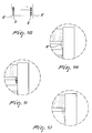
- a traditional spacer frame 3 is made of finely perforated hollow metal or finely perforated hollow plastics containing the hygroscopic material (or desiccant) 4 and illustrate the two types of sealant used: in black, the butyl sealant 6, which acts as an initial bond between the components and as a seal (first seal) and is applied between the lateral surfaces 3p and 3s of the frame and the glass sheets 2; in hachure, the polysulfide or polyurethane or silicone sealant 7, which has a function of elastic cohesion and mechanical strength (second seal) and is applied between the outer surface of the spacer frame 3 and the faces of the glass sheets 2 up to their edge.
- the butyl sealant 6 which acts as an initial bond between the components and as a seal (first seal) and is applied between the lateral surfaces 3p and 3s of the frame and the glass sheets 2
- in hachure the polysulfide or polyurethane or silicone sealant 7, which has a function of elastic cohesion and mechanical strength (second seal
- Figures 1D , IE illustrate the spacer frame obtained by means of the spacer profile 3 made of expanded synthetic material of the dual seal type, covered with adhesive 5 (first seal), and illustrate the sealant 7 that constitutes the second seal, which is generally obtained with hot melt but also with polysulfide or polyurethane or silicone.
- the reference numeral 8 designates the gas (which obviously is not visible) contained in the chamber delimited by the spacer frame 3 and by the glass sheets 2 (a gas which of course can be present in all the other Figures 1A-1F as well).
- Figure 1F illustrates the spacer frame obtained by means of a spacer profile 3 made of expanded synthetic material of the TriSeal TM type, covered with adhesive 5 (first seal) already in its supply condition and spread with butyl sealant 6 (second seal) by means of the device according to the present application and spread with polysulfide or polyurethane or silicone sealant 7 (third seal) in a known machine downstream of the device according to the present application.
- FIGS 1A ö1F show the importance of the spacer frame in the composition of the insulating glazing unit 1, especially in the embodiments in which the thicknesses of the glass sheets 2 and accordingly the weight are substantial (the case of laminated glass sheets), so that use of the spacer profile 3 made of expanded synthetic material, whose lateral faces 3p and 3s are coated with highly effective acrylic adhesive 5, be it of the "DualSeal” or “TriSeal” technology, turns out to be particularly valid, because it allows the instantaneous coupling of the glass sheets 2 to the spacer 3 already after mating, other than the butyl sealant alone according to the background art with a spacer profile made of metallic material or plastics, in which said coupling is provided, in expectance of the catalytic reaction of the two-part sealant 7, exclusively to the butyl sealant 6, which is thermoplastic and does not bear loads and is subject to viscous flow.
- the reference numeral 3 designates the spacer profile made of expanded synthetic material, without excluding operation of the machine also with spacer profiles made of a different material, as long as it is compatible with the mechanisms that will be described hereinafter;
- the reference numerals 3p and 3s designate respectively its first (3p) and second (3s) lateral faces that mate with the glass sheets 2;
- the reference numeral 2 designates the glass sheets (two, or more in the case of an insulating glazing unit composed of more than two glass sheets);
- the reference numeral 1 designates the insulating glazing unit as an assembly of the components 2 to 8.
- the reference numeral 11 designates an electrical/electronic panel
- the reference numeral 12 designates a control post
- the reference numeral 13 designates protective structures, be they of the type of mechanical barriers or optical barriers or laser barriers or electrically sensitive mats etcetera, since particular attention is given not only to the functional, economic and ergonomic aspects of the content of the present invention but also to the aspects related to prevention of accidents, which is inherently improved with respect to the background art indeed by means of the particular automation that is achieved with the present invention.
- Four-digit numbering is also used to refer to the machines that belong to the complete production line of the insulating glazing unit 1 and are complementary to the machine designated by the reference numeral 1000, which constitutes the machine that contains the device according to the present invention.
- the axis of the lower support/conveyance belts 802, 902 is inclined by approximately up to 6° with respect to the horizontal plane, and therefore “slightly inclined with respect to the horizontal” shall be understood when “horizontal” or “substantially horizontal” are used.
- thermoplastic sealant 6 i.e., the parts used in dual seal technology, which does not use the intermediate thermoplastic sealant. It is thus possible to implement the mechanisms and functions for feeding the second thermoplastic sealant related to TriSeal TM technology, to thus understand inventive aspects of the invention.
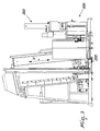
- the glass sheet 2 which originates from the preceding processing machine 4000, in the specific case a washing unit, is either loaded manually or by means of a loading unit onto the inlet conveyor 801 of the machine according to the present invention, advances, carried by the support and traction belts 802, and more specifically (in terms of synchronization between the actuators) by means of a sucker-fitted carriage 101 actuated by a synchronous motor 102 through a mechanical transmission consisting of a reduction unit 103 and a pinion 104 and rack 105 (a transmission which is not visible in Figure 7 and is not numbered but is known), up to a slowing sensor and to a stop device, both of which are known, so as to position the glass sheet 2 and allow the beginning of the process for applying the spacer profile 3 against the glass sheet 2.
- the head assembly 200 which can move vertically because it is applied to the vertical carriage 201, by the action of the synchronous motor 202 and the reduction unit 203, which actuate the pinion 204 that interacts with the rack 205, has been positioned in the process start condition.
- the synchronized motion of the glass sheet 2 actuated by the synchronous motor 102 that acts by means of the reduction unit 103 and a mechanical transmission of the type with a pinion 104/rack 105 (the reduction unit 103, the pinion 104 and the rack 105 not being visible in Figure 7 but being known) on the sucker-fitted carriage 101 provided with suckers 106 (and by the action of the parallel mechanical belt conveyors 802, 902 consisting of known components which operate on the lower edge of the glass sheet 2, said conveyors actuated by a synchronous motor for maintaining synchronization with the sucker-fitted carriage) and the synchronized motion of the belt transmission device 210a and 210b cause the tracing of the mutual path of the spacer profile 3/glass sheet 2 that corresponds to the first lower side 2a (as defined in Figure 19A ) of the glass sheet 2.
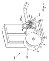
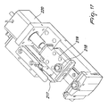
- the arrangement of said head is slightly inclined with respect to the plane of the glass sheet 2 and some components of the head 200, such as for example the wheel 218 that operates on the face 3s and can move on a slider 219 by means of the action of the actuator 220, for example of the step motor type, are provided with an axial motion, for adapting to the different thicknesses of the spacer profile 3 (thickness being the distance between its faces 3p, 3s, measured in the station 400 as mentioned hereinafter), and others, such as for example the sliding blocks 224 and 225, can be moved away by known mechanisms for eliminating interference with the spacer profile 3 once it is applied, as shown in Figure 18 .
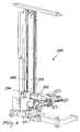
- the spool 9 (designated by a reference numeral in Figures 2 and 4 , but masked by the enclosure that protects it against contamination by atmospheric humidity, since the spacer profile 3 contains, dispersed within its mass, the hygroscopic material 4), whose rotation is controlled by a known non-synchronous motor which operates by means of a likewise known reduction unit, and likewise known adjustment systems with a dandy roll and a proximity sensor, feeds the spacer profile 3 not so much in step with the activity of the application head 200 but autonomously in step with the apparatus 500 directly downstream of said spool, which performs the extrusion of the second sealant 6.
- the motor that drives the rotation of the spool 9 is fedback by the position of the dandy roll 401 that interacts with a potentiometer 402.
- the dandy roll and the potentiometer perform feedback and fine control, while an equally known sensor 403 provides information related to the diameter of the spool for coarse control of the rim speed range of said spool.
- the films 5' that protect the acrylic adhesive 5 that is spread on the lateral faces 3p and 3s of the spacer profile 3 are removed conveniently by means of winding reels 404a, 404b, which are also known and are actuated by respective motors that engage them directly, their electronic actuation being simply of the torque-control type.
- a thickness measurement device 405 that belongs to the section 400 provides the thickness parameter to the mechanisms of the head 200 that must adapt to the thickness of the spacer profile 3.
- the actuation means 230 which consists of: support 231, motor 232, reduction unit 233, pinion 234 and ring gear 235
- the head 200 is activated in its vertical motion V by the translation actuation means 201 (which consist of: vertical slider 201, motor 202, reduction unit 203, pinion 204 and rack 205).
- the spacer profile 3, guided through the toothed belts 210a and 210b, that constitute traction means for the synchronous traction of the profile 3 traces the path that corresponds to the first vertical side 2b (the numbering of the sides being the numbering of Figure 19A ). It is intuitive to deduce the continuations of the path of the remaining sides 2c and 2d of the glass sheet 2 as repetitions of the preceding steps.
- Control of the position of the glass sheet 2, in particular of its initial position, is fundamental for the correct operation of the process performed by the head 200, both in the rectangular version and in particular in the contoured version, for coordinating the horizontal movements H of the glass sheet 2 and the vertical movement V of the vertical carriage 201 that carries the head 200.
- a sensor detects the position of the edge of the glass sheet and, by means of the logic control of the PLC (programmable logic controller), provides the information, related to the beginning and the end of the sides of the glass sheet 2, respectively to the actuation systems of the transfer belts 802 and 902, of the sucker-fitted carriage 101 along the axis H (and/or to the actuation system of the vertical movement of the vertical carriage 201 along the axis V) and the actuation system of the belt transmission device 210a and 210b along the axis T.
- PLC programmable logic controller
- the information related to its shape is entered electronically by means of known methods (keyboard, floppy disk, net, etcetera) and in addition to the actuation systems described above, which operate on the synchronous motors for actuating the traction systems 802, 902, on the synchronous motor 101, on the synchronous motor 201, on the synchronous motors 214a and 214b, the actuation of the synchronous motor 232 also is involved, so that the four motions: the horizontal motion H of the glass sheet 2, the vertical motion V of the head 200, the translational motion T of the belts device, the rotary motion ⁇ of the head 200, are linked electrically/electronically for following the shape of the glass sheet 2 in the distribution of the spacer profile 3.
- the following apparatuses are arranged respectively upstream of the application head 200: the melting assembly 300, the unwinding assembly 400, the extrusion assembly 500, the compensation assembly 600 and the traction assembly 700, the latter being however jointly connected to the application head 200.
- these apparatuses (300 and 400 of a known construction) perform the following processes: [300] melting of the butyl sealant 6 (but not exclusively limited to butyl sealant); [400] controlled unwinding of the spool 9 that contains the spacer profile 3 provided with receptacles 6' and removal of the protective films 5'; [500] symmetrical and controlled extrusion of the sealant 6 on the receptacles 6'; [600] compensation of the offsets between the extrusion process and the application process (said compensation is described hereinafter in the inventive part of the present application); [700] traction from the compensation apparatus to the application head.
- these apparatuses are composed as follows:
- extruder 500 substantially comprises what is taught in IT-TV2008A000047 and known machines built in the field of the production of spacer frames and/or profiles 3, whether made of rigid material or of flexible material. it is therefore mainly composed of:
- An important aspect of the inventive method provided comprises a management of such device, which is independent of the upstream and downstream processes and in particular is independent of the process for applying the spacer profile 3 on the glass sheet 2, so as to optimize the extrusion and distribution of the thermoplastic sealant 6 in the receptacles 6' of the spacer profile 3.
- Achieving this characteristic can not only cover the steps of complete production of an insulating glazing unit 1 but can even extend to the production of multiple insulating glazing units 1 up to the total depletion of the spacer profile 3 contained in the spool 9. This occurs exclusively in relation to the peculiarities of the insulating glazing units to be produced, the production speeds and the production pauses, and can in any case be performed by operating on the extension of the operating range of the device described in the subsequent assembly 600.
- An inventive aspect of the process and of the machine according to the present invention comprises components interposed between the series of assemblies 300, 400, 500 and the assembly 200, namely:
- the quantity of spacer profile 3 that is unwound from the spool 9 in the section 400 and coated with butyl sealant 6 in the station 500 must on average correspond to the quantity of spacer profile 3 that is used by the application head 200 and corresponds to the extension of one or more perimeters of the spacer frame 3 used in the manufacture of the insulating glazing unit 1.
- this does not mean that the instantaneous flow of the spacer profile 3 in the two processes performed by the apparatus 500 and by the apparatus 200, respectively, must be the same.
- a non-Newtonian fluid is in fact difficult to control in transitions, especially if they are particularly sudden, because its viscosity varies with the flow-rate, and the flow-rate in extrusions, in addition to depending on the degree of throttling of the valves and on the pressure variation, depends on the viscosity (an algorithm which is therefore very complex if not unsolvable).
- the background art in the field uses the second solution, which applies for the present invention also, with the advantageous difference that the present invention allows at least three new possibilities with respect to the background art:
- this third possibility is highly advantageous, since in the background art forced stops/restarts, even during processing of the individual insulating glazing panel 1, are instead occurring.
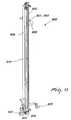
- compensation assembly 600 which is different from the dandy roll according to the background art and of the type of those used in the assembly 400, at the beginning of the assembly 600 and in the assembly 700, whose position interacts with actuators that modify the flows of material upstream or downstream of said dandy roll.
- This compensation assembly in fact acts with an opposite logic, which is to accumulate/return all the material that derives from the difference of the flows of the processes upstream and downstream thereof, respectively.
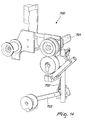
- traction assembly 700 is a device that is interposed between the compensation assembly 600 and the head 200 and is adapted to return to the compensation assembly 600 the demand for spacer profile 3 or the return due to excess of the spacer profile 3. This is achieved by means of the synchronous actuator 701 and the signal of the potentiometer 702, controlled by the dandy roll 703, which interact with the actuator 604 that determines the position of the roller 608.
- Figures 20 and 21 refers to a machine 1000 for applying a spacer profile 3, in which the source machine (washing unit) 4000 is placed to the left and the destination machine (mating unit) 5000 is arranged to the right of it (with reference to the flow of the process); it is easy to imagine a description and corresponding figures in the case of mirror-symmetrical or otherwise different arrangements, such as those of Figures 2 to 18 , which illustrate an orientation that is opposite to the orientation of Figures 20 and 21 .
- the mechanical solutions for the movement of the compensation roller 608; the actuation means, which can be electrical, electrical-electronic, pneumatic, oil pressure-operated and/or combined, etcetera; the control means, which can be electronic or fluidic and/or combined, etcetera, can all be provided, according to the requirements, by known equivalent means.
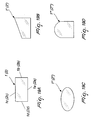
- An important process and construction variation consists in the logical combination of the actuation systems for horizontal translational motion H of the glass sheet [assembly 100], for vertical translation V of the head [assembly 200] for rotation ⁇ of the head [also assembly 200] and translational motion T of the belts of the belt transmission device 210a, 210b [assembly 200], respectively, for allowing the application of the spacer profile 3 on glass sheets 2' ( Figure 19B ) whose shape is other than rectangular because it is a regular or irregular polygonal shape, or on glass sheets 2" ( Figure 19C ) whose shape is other than rectangular because it is curvilinear, or on glass sheets 2'" ( Figure 19D ) whose shape is other than rectangular because it consists of linear and curvilinear parts.
- the materials and the dimensions may be any according to requirements, in particular those arising from the dimensions (base and height) of the glass sheets 2.
- insulating glazing units required has been increased and improved by all those configurations that require the use of special types of glass which are therefore heavy like the ones described in the preamble of the description (and in particular very thick ones, such as tempered glass sheets, laminated glass sheets, and armored glass sheets), which are thus coupled advantageously right from the very first mating with the spacer frame 3, if said frame is of the type to which the present invention relates, differently from the traditional type, which requires catalysis of the final sealant before the joint between the glass sheets and the frame can be subjected to stresses by means of mechanical loads.
- shapes that differ from the rectangular one because they are polygonal or curvilinear or mixed are successfully obtainable according to the present invention, which is aimed at providing according to best practice the intermediate seal 6 particularly in a manner that is not disturbed by discontinuities, interruptions, irregularities that are typical of the methods of the background art.
- the machine with the device according to the present invention can be inserted easily on lines for the production of an insulating glazing unit of the traditional type (i.e., the one with the spacer frame made of a hollow profile according to Figures 1A, 1B, 1C ), making said lines conveniently dual-purpose, i.e., operative both with a traditional spacer frame and with a spacer frame made of expanded synthetic material, or rather triple-purpose, since the spacer frame made of expanded synthetic material can be both of the dual seal type and of the TriSeal TM type and the application head 200 can apply both said types of spacer profile 3.
- the traditional type i.e., the one with the spacer frame made of a hollow profile according to Figures 1A, 1B, 1C
- the spacer frame made of expanded synthetic material can be both of the dual seal type and of the TriSeal TM type and the application head 200 can apply both said types of spacer profile 3.
- the traditional dual seal system with a spacer frame made of hollow profiled aluminum or hollow profiled plastic suffers from the fact that due to the rigidity of the cross-section of the profile that constitutes the frame, the inevitable differential expansions between the glass sheet 2 exposed to a higher temperature and the glass sheet 2 exposed to a lower temperature entail the flow of the butyl thermoplastic sealant, compromising its efficiency and thus reducing the tightness to water vapor and gas.
- the differential expansions cited above are withstood due to the elastic deformability of the profile itself. Therefore, the second thermoplastic butyl sealant 6 does not flow with respect to the glass sheet both due to the presence of the first acrylic adhesive sealant, which keeps the spacer profile 3 locally coupled to the glass sheet 2, and due to less stress, for an equal expansion, because said stress is attenuated by the elasticity of the spacer profile 3.
Landscapes
- Engineering & Computer Science (AREA)
- Civil Engineering (AREA)
- Structural Engineering (AREA)
- Securing Of Glass Panes Or The Like (AREA)
- Joining Of Glass To Other Materials (AREA)
- Laminated Bodies (AREA)
Claims (10)
- Automatische Maschine für das Auftragen eines Abstandhalterprofils (3), vorzugsweise aus einem ausgedehnten synthetischen Material, auf eine erste Glasscheibe (2), die ausgelegt ist, sich darauffolgend mit einer zweiten Glasscheibe (2) zu verbinden, um die Isolierverglasungseinheit (1) zu bilden, umfassend Fördereinrichtungen (801, 901) mit einer im Wesentlichen vertikalen Anordnungsebene, die mit Stütz- und Zugförderungsmitteln (802, 902) versehene Transportvorrichtungen enthalten, welche an der Kante der Glasscheibe (2) arbeiten; synchrone Übertragungsmittel (101), die auf der Fläche der Glasscheibe (2) entlang einer horizontalen Achse (H) arbeiten, dadurch gekennzeichnet, dass sie Folgendes umfasst: einen Auftragungskopf (200) für das Auftragen des Abstandhalterprofils (3), wobei der Auftragungskopf (200) der Kontur der Glasscheibe (2) folgt und eine synchrone Verschiebungsbewegung entlang einer vertikalen Achse (V), angetrieben durch Übertragungsmittel (201), und eine synchrone Drehbewegung entlang der Drehachse (ϕ), angetrieben durch Übertragungsmittel (230), aufweist; im Kopf (200) angeordnete Mittel (210a, 210b) für die synchrone Zugförderung des Abstandhalterprofils (3), wobei das Abstandhalterprofil (3) auf jeder seiner Seiten (3p, 3s) zwei Bereiche hat, die vorgesehen sind, um für das Aufnehmen von Dichtungsmitteln geeignet zu sein, jeweils mit einer Haftfunktion (5) bzw. einer Dichtungsfunktion (6), wobei das Abstandhalterprofil (3) von einer Spule (9) stammt, in der das Abstandhalterprofil (3) nur mit dem haftenden Dichtungsmittel (5) bereitgestellt ist, geschützt durch eine entfernbare Folie (5'), und wobei das Abwickeln der Spule auf regulierte Art gesteuert wird, und wobei das Abstandhalterprofil (3) an den Stellen geschnitten wird, die für das Bilden der Ecken und Scheitelpunkte des gebildeten Rahmens geeignet sind, und dann mit der Seite (3p) auf die Glasscheibe (2) durch Mechanismen des Kopfes (200) mit Unterbrechungen auf die Glasscheibe (2) aufgetragen wird, und in Abständen auf weitere Glasscheiben (2), die zu nachfolgenden Isolierverglasungseinheiten (1) gehören, wobei die Auftragung des zweiten dichtenden Dichtungsmittels (6) in einer Extrusionsanordnung (500) durchgeführt wird, die sich zwischen der Abwickelvorrichtung (400) der Spule (9) und dem Auftragungskopf (200) befindet, und wobei Düsen (505p, 505s) der Extrusionsanordnung (500) für die Modulation hinsichtlich ihrer Flussrate und für unterbrechungsfreies Arbeiten hinsichtlich ihrer Flussrate betätigt werden, zumindest während der Auftragung des gesamten Abstandhalterprofils (3) auf die entsprechende Glasscheibe (2), die nach dem Verbinden mit einer zweiten Glasscheibe (2) eine vollständige Isolierverglasungseinheit (1) darstellt.
- Automatische Maschine nach Anspruch 1, dadurch gekennzeichnet, dass die Kontinuität der Extrusion durch eine mit einem Positionierungsrad (601) versehene Kompensationsanordnung (600) bereitgestellt wird, deren Steuerung durch die synchrone Betätigung eines Motors (604) als Funktion einer Aktivität mit Unterbrechungen des Auftragungskopfes (200) und einer Aktivität ohne Unterbrechungen der Extrusionsanordnung (500) angetrieben wird.
- Automatische Maschine nach Anspruch 1, dadurch gekennzeichnet, dass mindestens eine der Düsen (505p, 505s) für die Extrusion des zweiten Dichtungsmittels (6) mittels einer Betätigungseinrichtung (506) in Bezug zur gegenüberliegenden Düse und folglich in Bezug zu den Flächen (3p, 3s) des Abstandhalterprofils (3) einstellbar ist, sowohl zum Bereitstellen von symmetrischem und optimalem Spielraum für die Extrusion in Kontakt mit den Flächen (3p, 3s) und für das Anpassen an die Querabmessung des Abstandhalterprofils (3), gemessen durch eine Messvorrichtung (405), die sich in der Abwicklungsvorrichtung (400) befindet.
- Automatische Maschine nach Anspruch 1, dadurch gekennzeichnet, dass die Modulation der Flussrate des zweiten Dichtungsmittels (6) mittels synchroner Betätigungseinrichtungen (508p, 508s) erfolgt, die elektrisch und logisch mit einer oder mehreren oder allen der folgenden Betätigungseinrichtungen verbunden sind: einem Synchronmotor (102) für die synchrone Zugförderung der Glasscheibe entlang der horizontalen Achse (H), einem Synchronmotor (202) für die synchrone Bewegung des Kopfes (200) entlang der vertikalen Achse (V), einem Synchronmotor (232) für die synchrone Drehung des Kopfes (200) entlang der Drehachse (ϕ), einem Synchronmotor (214a, 214b) für die Zugförderung des Abstandhalterprofils (3) entlang der Längsachse (T), einem Synchronmotor (504) für die Zugförderung des Abstandhalterprofils (3) an den Extrusionsdüsen (505p, 505s), einem Motor (604) der Kompensationsanordnung (600) und einem Synchronmotor (701) der Zugförderungsanordnung (700).
- Automatische Maschine nach Anspruch 3, dadurch gekennzeichnet, dass die Modulation der Flussrate des zweiten Dichtungsmittels (6) mittels Flusssteuerelementen (507p, 507s) vom Spulentyp erfolgt, die durch die Synchronmotoren (508p, 508s) angetrieben werden.
- Automatische Maschine nach Anspruch 3, dadurch gekennzeichnet, dass die Modulation der Flussrate des zweiten Dichtungsmittels (6) mittels Flusssteuerelementen (507p, 507s) vom Nadeltyp erfolgt, die durch die Synchronmotoren (508p, 508s) angetrieben werden.
- Automatische Maschine nach Anspruch 3 bis 6, dadurch gekennzeichnet, dass die Modulation der Flussrate des zweiten Dichtungsmittels (6) für jede Düse (505p, 505s) unabhängig erfolgt.
- Automatisches Verfahren für das Auftragen eines Abstandhalterprofils (3), vorzugsweise aus einem ausgedehnten synthetischen Material, auf eine erste Glasscheibe (2), die darauffolgend mit einer zweiten Glasscheibe (2) verbunden wird, um die Isolierverglasungseinheit (1) zu bilden, befördert entlang einer Ebene, die eine im Wesentlichen vertikale Anordnung hat, synchron entlang einer horizontalen Achse (H) und mit einer relativen Bewegung der Glasscheibe (2), wobei ein Auftragungskopf (200) für das Auftragen des Abstandhalterprofils (3) der Kontur der Glasscheibe (2) in einem begrenzten Abstand von ihrem Rand folgt, und wobei ein Abstandhalterprofil (3) bereitgestellt ist, das auf jeder seiner Seiten (3p, 3s) zwei Bereiche hat, die jeweils für ein Dichtungsmittel mit einer Haftfunktion (5) bzw. einer Dichtungsfunktion (6) ausgelegt sind, wobei das Abstandhalterprofil von einer Spule (9) stammt, in welcher Spule das Abstandhalterprofil (3) nur mit dem haftenden Dichtungsmittel (5) versehen bereitgestellt ist, geschützt durch eine entfernbare Folie (5'), und wobei die Spule auf eine Art abgewickelt wird, die durch die folgenden Prozesse rückgeführt wird, und wobei das Abstandhalterprofil (3) an den Stellen geschnitten wird, die für das Bilden der Ecken und Scheitelpunkte des gebildeten Rahmens geeignet sind, und dann mit der Seite (3p) auf die Glasscheibe (2) aufgetragen wird, mit Unterbrechungen auf die Glasscheibe (2) und in Abständen auf weitere Glasscheiben (2), die zu nachfolgenden Isolierverglasungseinheiten (1) gehören, wobei die Auftragung des zweiten dichtenden Dichtungsmittels (6) in einem Schritt durchgeführt wird, der auf den Schritt für das Abwickeln der Spule (9) folgt und dem Schritt für die Auftragung des Abstandhalterprofils (3) auf die Glasscheibe (2) vorangeht, und wobei eine Extrusion des dichtenden Dichtungsmittels (6) ohne Unterbrechungen durchgeführt wird, obwohl die Auftragung des Abstandhalterprofils (3) auf die Glasscheibe (2) mit Unterbrechungen oder sogar in Abständen erfolgt.
- Verfahren nach Anspruch 8, dadurch gekennzeichnet, dass die Extrusionsflussrate des zweiten Dichtungsmittels (6) moduliert, aber nicht unterbrochen wird.
- Verfahren nach Anspruch 8, dadurch gekennzeichnet, dass die Kontinuität des Prozesses für die Extrusion des Dichtungsmittels (6) auf die Flächen (3p, 3s) des Abstandhalterprofils (3) vor dem Auftragungsprozess durch ein Kompensieren der Diskontinuität des Prozesses für die Auftragung des Abstandhalterprofils (3) auf die Glasscheibe (2) durch Akkumulation (600) des Abstandhalterprofils (3) erhalten wird, geschaltet zwischen dem Extrusionsprozess (500) des Dichtungsmittels (6) und dem Prozess (200) für das Auftragen des Abstandhalterprofils (3).
Applications Claiming Priority (1)
| Application Number | Priority Date | Filing Date | Title |
|---|---|---|---|
| ITTV2008A000129A IT1391489B1 (it) | 2008-10-17 | 2008-10-17 | Macchina automatica per l'estrusione continua di sigillante termoplastico su profilo distanziatore durante l'applicazione discontinua dello stesso su lastra di vetro e procedimento automatico per l'estrusione continua di sigillante termoplastico su profilo distanziatore durante l'applicazione discontinua dello stesso su lastra di vetro. |
Publications (2)
| Publication Number | Publication Date |
|---|---|
| EP2177703A1 EP2177703A1 (de) | 2010-04-21 |
| EP2177703B1 true EP2177703B1 (de) | 2014-07-16 |
Family
ID=40951632
Family Applications (1)
| Application Number | Title | Priority Date | Filing Date |
|---|---|---|---|
| EP09173315.4A Active EP2177703B1 (de) | 2008-10-17 | 2009-10-16 | Automatische Maschine zum Auftragen eines Abstandhalterprofils auf eine Glasscheibe sowie Verfahren dafür |
Country Status (3)
| Country | Link |
|---|---|
| US (1) | US8397780B2 (de) |
| EP (1) | EP2177703B1 (de) |
| IT (1) | IT1391489B1 (de) |
Cited By (5)
| Publication number | Priority date | Publication date | Assignee | Title |
|---|---|---|---|---|
| US8795568B2 (en) | 2007-11-13 | 2014-08-05 | Guardian Ig, Llc | Method of making a box spacer with sidewalls |
| US9228389B2 (en) | 2010-12-17 | 2016-01-05 | Guardian Ig, Llc | Triple pane window spacer, window assembly and methods for manufacturing same |
| US9260907B2 (en) | 2012-10-22 | 2016-02-16 | Guardian Ig, Llc | Triple pane window spacer having a sunken intermediate pane |
| US9309714B2 (en) | 2007-11-13 | 2016-04-12 | Guardian Ig, Llc | Rotating spacer applicator for window assembly |
| EP4686800A1 (de) | 2024-07-29 | 2026-02-04 | Forel S.P.A. Unipersonale | Vorrichtung und verfahren zum anbringen eines flexiblen abstandhalters für isolierglas |
Families Citing this family (10)
| Publication number | Priority date | Publication date | Assignee | Title |
|---|---|---|---|---|
| WO2011008860A1 (en) | 2009-07-14 | 2011-01-20 | Infinite Edge Technologies, Llc | Stretched strips for spacer and sealed unit |
| EP2580418B1 (de) * | 2010-06-10 | 2014-08-13 | Guardian IG, LLC | Fensterabstandhalteraufträger |
| US9689196B2 (en) * | 2012-10-22 | 2017-06-27 | Guardian Ig, Llc | Assembly equipment line and method for windows |
| US9656356B2 (en) | 2013-01-22 | 2017-05-23 | Guardian Ig, Llc | Window unit assembly station and method |
| US10289930B2 (en) | 2017-02-09 | 2019-05-14 | Glasstech, Inc. | System and associated for online measurement of the optical characteristics of a glass sheet |
| US10267750B2 (en) * | 2017-02-09 | 2019-04-23 | Glasstech, Inc. | System and associated method for online detection of small defects on/in a glass sheet |
| IT201700071422A1 (it) * | 2017-06-27 | 2018-12-27 | Forel Spa | Impianto automatico e procedimento automatico per la fabbricazione ad elevata produttivita’ del vetro isolante costituito da almeno due lastre di vetro ed almeno un telaio distanziatore |
| US11352831B2 (en) | 2019-05-24 | 2022-06-07 | PDS IG Holding LLC | Glass seal tracking spacer applicator |
| CN111515585A (zh) * | 2020-04-29 | 2020-08-11 | 安徽万朗磁塑股份有限公司 | 一种冰箱门密封条的全自动焊接机 |
| IT202100025355A1 (it) * | 2021-10-04 | 2023-04-04 | Forel S P A Unipersonale | Procedimento ed apparato per la costruzione e l’applicazione di un telaio distanziatore rigido per vetro isolante |
Family Cites Families (5)
| Publication number | Priority date | Publication date | Assignee | Title |
|---|---|---|---|---|
| FR2449222A1 (fr) * | 1979-02-15 | 1980-09-12 | Kaeuferle Stahlbau J | Perfectionnements aux procedes et dispositifs de fabrication de plaques composites, notamment de glaces doubles |
| DE10212359B4 (de) * | 2002-03-20 | 2005-10-06 | Peter Lisec | Verfahren und Vorrichtung zum maschinellen Applizieren eines Abstandhalterbandes auf eine Glasscheibe |
| DE10350312B4 (de) | 2003-10-28 | 2005-12-01 | Peter Lisec | Verfahren und Vorrichtung zum Applizieren eines elastoplastischen Bandes beim Herstellen einer Isolierglasscheibe |
| WO2005078227A1 (en) * | 2004-02-04 | 2005-08-25 | Edgetech I.G., Inc. | A method for forming an insulating glazing unit |
| ITTV20040117A1 (it) | 2004-10-20 | 2005-01-20 | For El Base Di Vianello Fortun | Macchina automatica per l'applicazione di profilo distanziatore su lastra di vetro e procedimento automatico per l'applicazione di profilo distanziatore su lastra di vetro. |
-
2008
- 2008-10-17 IT ITTV2008A000129A patent/IT1391489B1/it active
-
2009
- 2009-10-15 US US12/588,424 patent/US8397780B2/en active Active
- 2009-10-16 EP EP09173315.4A patent/EP2177703B1/de active Active
Cited By (7)
| Publication number | Priority date | Publication date | Assignee | Title |
|---|---|---|---|---|
| US8795568B2 (en) | 2007-11-13 | 2014-08-05 | Guardian Ig, Llc | Method of making a box spacer with sidewalls |
| US9127502B2 (en) | 2007-11-13 | 2015-09-08 | Guardian Ig, Llc | Sealed unit and spacer |
| US9187949B2 (en) | 2007-11-13 | 2015-11-17 | Guardian Ig, Llc | Spacer joint structure |
| US9309714B2 (en) | 2007-11-13 | 2016-04-12 | Guardian Ig, Llc | Rotating spacer applicator for window assembly |
| US9228389B2 (en) | 2010-12-17 | 2016-01-05 | Guardian Ig, Llc | Triple pane window spacer, window assembly and methods for manufacturing same |
| US9260907B2 (en) | 2012-10-22 | 2016-02-16 | Guardian Ig, Llc | Triple pane window spacer having a sunken intermediate pane |
| EP4686800A1 (de) | 2024-07-29 | 2026-02-04 | Forel S.P.A. Unipersonale | Vorrichtung und verfahren zum anbringen eines flexiblen abstandhalters für isolierglas |
Also Published As
| Publication number | Publication date |
|---|---|
| ITTV20080129A1 (it) | 2010-04-18 |
| US8397780B2 (en) | 2013-03-19 |
| US20100096069A1 (en) | 2010-04-22 |
| EP2177703A1 (de) | 2010-04-21 |
| IT1391489B1 (it) | 2011-12-23 |
Similar Documents
| Publication | Publication Date | Title |
|---|---|---|
| US8397780B2 (en) | Automatic machine for applying a spacer profile on a glass sheet, and method therefor | |
| US7922842B2 (en) | Automatic device and method for perimetric sealing of insulating glazing units | |
| EP2580418B1 (de) | Fensterabstandhalteraufträger | |
| EP2093370B1 (de) | Automatikvorrichtung zum Befüllen isolierender Verglasungselemente und entsprechendes Verfahren | |
| EP2862644B1 (de) | Automatische Maschine und automatisches Verfahren zum Biegen und Kalandrieren von Abstandsprofilen zur Herhalten von Abstandhalterrahmen für eine Isolierverglasungseinheit | |
| US7094128B2 (en) | Automatic machine for grinding the borders of glass panes | |
| EP3645822B1 (de) | Automatische vorrichtung und automatisches verfahren zur hochproduktiven herstellung der isolierverglasungseinheit, die aus mindestens zwei glasscheiben und mindestens einem abstandsrahmen zusammengesetzt ist | |
| US7357169B2 (en) | Automatic machine for applying a spacer tape made of flexible material to flat glass panes, particularly glass panes for manufacturing double-glazing units | |
| EP3278946B1 (de) | Dosierungsvorrichtung zum kontinuierlichen extrudieren und anwenden eines abstandhalterprofils einer isolierverglasungseinheit | |
| EP2460971B1 (de) | Verfahren zum Versiegeln einer Umfangsnut einer Isolierverglasung | |
| EP1297901B1 (de) | Vorrichtung sowie Verfahren zum automatisch beidseitigen Extrudieren und Beschichten von Abstandshalterrahmen für Isolierglasscheiben mit einer Dichtmasse | |
| EP2862672A1 (de) | Automatische Maschine und automatisches Verfahren zum lokalen Entfernen von Überzügen auf Glasplatten | |
| US10890026B2 (en) | Automatic machine for alternable application of a plurality of flexible spacer profiles on a glass sheet | |
| US12180782B2 (en) | Device and procedure for extrusion and application of spacer profile of an insulating glass | |
| EP1655443B1 (de) | Vorrichtung zum automatischen Auftragen von Dichtmasse auf der Innenseite einer gestuften Isolierglasscheibe | |
| US11639628B2 (en) | Automatic machine and automatic method for sealing the perimetric edge of the insulating glazing unit having irregular geometry | |
| US8161905B2 (en) | Automatic machine for versatile and alternative application of at least two types of sealant along the perimetric rim of an insulating glazing unit | |
| ITTV20080047A1 (it) | Macchina automatica per l'estrusione di sigillante termoplastico su profilo distanziatore e per l'aplicazione dello stesso su lastra di vetro e procedimento automatico per l'estrusione di sigillante termoplastico su profilo distanziatore e per l'appl |
Legal Events
| Date | Code | Title | Description |
|---|---|---|---|
| PUAI | Public reference made under article 153(3) epc to a published international application that has entered the european phase |
Free format text: ORIGINAL CODE: 0009012 |
|
| AK | Designated contracting states |
Kind code of ref document: A1 Designated state(s): AT BE BG CH CY CZ DE DK EE ES FI FR GB GR HR HU IE IS IT LI LT LU LV MC MK MT NL NO PL PT RO SE SI SK SM TR |
|
| AX | Request for extension of the european patent |
Extension state: AL BA RS |
|
| 17P | Request for examination filed |
Effective date: 20101020 |
|
| GRAP | Despatch of communication of intention to grant a patent |
Free format text: ORIGINAL CODE: EPIDOSNIGR1 |
|
| INTG | Intention to grant announced |
Effective date: 20140129 |
|
| GRAS | Grant fee paid |
Free format text: ORIGINAL CODE: EPIDOSNIGR3 |
|
| GRAA | (expected) grant |
Free format text: ORIGINAL CODE: 0009210 |
|
| RAP1 | Party data changed (applicant data changed or rights of an application transferred) |
Owner name: FOREL SPA |
|
| AK | Designated contracting states |
Kind code of ref document: B1 Designated state(s): AT BE BG CH CY CZ DE DK EE ES FI FR GB GR HR HU IE IS IT LI LT LU LV MC MK MT NL NO PL PT RO SE SI SK SM TR |
|
| REG | Reference to a national code |
Ref country code: GB Ref legal event code: FG4D |
|
| REG | Reference to a national code |
Ref country code: CH Ref legal event code: EP |
|
| REG | Reference to a national code |
Ref country code: IE Ref legal event code: FG4D |
|
| REG | Reference to a national code |
Ref country code: AT Ref legal event code: REF Ref document number: 677783 Country of ref document: AT Kind code of ref document: T Effective date: 20140815 |
|
| REG | Reference to a national code |
Ref country code: DE Ref legal event code: R096 Ref document number: 602009025286 Country of ref document: DE Effective date: 20140828 |
|
| REG | Reference to a national code |
Ref country code: CH Ref legal event code: NV Representative=s name: MODIANO AND PARTNERS SA, CH |
|
| REG | Reference to a national code |
Ref country code: CH Ref legal event code: PCAR Free format text: NEW ADDRESS: VIA CALLONI, 1, 6900 LUGANO (CH) |
|
| REG | Reference to a national code |
Ref country code: NL Ref legal event code: VDEP Effective date: 20140716 |
|
| REG | Reference to a national code |
Ref country code: LT Ref legal event code: MG4D |
|
| PG25 | Lapsed in a contracting state [announced via postgrant information from national office to epo] |
Ref country code: SE Free format text: LAPSE BECAUSE OF FAILURE TO SUBMIT A TRANSLATION OF THE DESCRIPTION OR TO PAY THE FEE WITHIN THE PRESCRIBED TIME-LIMIT Effective date: 20140716 Ref country code: FI Free format text: LAPSE BECAUSE OF FAILURE TO SUBMIT A TRANSLATION OF THE DESCRIPTION OR TO PAY THE FEE WITHIN THE PRESCRIBED TIME-LIMIT Effective date: 20140716 Ref country code: PT Free format text: LAPSE BECAUSE OF FAILURE TO SUBMIT A TRANSLATION OF THE DESCRIPTION OR TO PAY THE FEE WITHIN THE PRESCRIBED TIME-LIMIT Effective date: 20141117 Ref country code: GR Free format text: LAPSE BECAUSE OF FAILURE TO SUBMIT A TRANSLATION OF THE DESCRIPTION OR TO PAY THE FEE WITHIN THE PRESCRIBED TIME-LIMIT Effective date: 20141017 Ref country code: NO Free format text: LAPSE BECAUSE OF FAILURE TO SUBMIT A TRANSLATION OF THE DESCRIPTION OR TO PAY THE FEE WITHIN THE PRESCRIBED TIME-LIMIT Effective date: 20141016 Ref country code: LT Free format text: LAPSE BECAUSE OF FAILURE TO SUBMIT A TRANSLATION OF THE DESCRIPTION OR TO PAY THE FEE WITHIN THE PRESCRIBED TIME-LIMIT Effective date: 20140716 Ref country code: ES Free format text: LAPSE BECAUSE OF FAILURE TO SUBMIT A TRANSLATION OF THE DESCRIPTION OR TO PAY THE FEE WITHIN THE PRESCRIBED TIME-LIMIT Effective date: 20140716 Ref country code: BG Free format text: LAPSE BECAUSE OF FAILURE TO SUBMIT A TRANSLATION OF THE DESCRIPTION OR TO PAY THE FEE WITHIN THE PRESCRIBED TIME-LIMIT Effective date: 20141016 |
|
| PGFP | Annual fee paid to national office [announced via postgrant information from national office to epo] |
Ref country code: CH Payment date: 20141029 Year of fee payment: 6 |
|
| PG25 | Lapsed in a contracting state [announced via postgrant information from national office to epo] |
Ref country code: LV Free format text: LAPSE BECAUSE OF FAILURE TO SUBMIT A TRANSLATION OF THE DESCRIPTION OR TO PAY THE FEE WITHIN THE PRESCRIBED TIME-LIMIT Effective date: 20140716 Ref country code: NL Free format text: LAPSE BECAUSE OF FAILURE TO SUBMIT A TRANSLATION OF THE DESCRIPTION OR TO PAY THE FEE WITHIN THE PRESCRIBED TIME-LIMIT Effective date: 20140716 Ref country code: PL Free format text: LAPSE BECAUSE OF FAILURE TO SUBMIT A TRANSLATION OF THE DESCRIPTION OR TO PAY THE FEE WITHIN THE PRESCRIBED TIME-LIMIT Effective date: 20140716 Ref country code: IS Free format text: LAPSE BECAUSE OF FAILURE TO SUBMIT A TRANSLATION OF THE DESCRIPTION OR TO PAY THE FEE WITHIN THE PRESCRIBED TIME-LIMIT Effective date: 20141116 Ref country code: CY Free format text: LAPSE BECAUSE OF FAILURE TO SUBMIT A TRANSLATION OF THE DESCRIPTION OR TO PAY THE FEE WITHIN THE PRESCRIBED TIME-LIMIT Effective date: 20140716 |
|
| REG | Reference to a national code |
Ref country code: DE Ref legal event code: R097 Ref document number: 602009025286 Country of ref document: DE |
|
| PG25 | Lapsed in a contracting state [announced via postgrant information from national office to epo] |
Ref country code: CZ Free format text: LAPSE BECAUSE OF FAILURE TO SUBMIT A TRANSLATION OF THE DESCRIPTION OR TO PAY THE FEE WITHIN THE PRESCRIBED TIME-LIMIT Effective date: 20140716 Ref country code: SK Free format text: LAPSE BECAUSE OF FAILURE TO SUBMIT A TRANSLATION OF THE DESCRIPTION OR TO PAY THE FEE WITHIN THE PRESCRIBED TIME-LIMIT Effective date: 20140716 Ref country code: EE Free format text: LAPSE BECAUSE OF FAILURE TO SUBMIT A TRANSLATION OF THE DESCRIPTION OR TO PAY THE FEE WITHIN THE PRESCRIBED TIME-LIMIT Effective date: 20140716 Ref country code: RO Free format text: LAPSE BECAUSE OF FAILURE TO SUBMIT A TRANSLATION OF THE DESCRIPTION OR TO PAY THE FEE WITHIN THE PRESCRIBED TIME-LIMIT Effective date: 20140716 Ref country code: DK Free format text: LAPSE BECAUSE OF FAILURE TO SUBMIT A TRANSLATION OF THE DESCRIPTION OR TO PAY THE FEE WITHIN THE PRESCRIBED TIME-LIMIT Effective date: 20140716 |
|
| REG | Reference to a national code |
Ref country code: DE Ref legal event code: R082 Ref document number: 602009025286 Country of ref document: DE Representative=s name: SCHAUMBURG & PARTNER PATENTANWAELTE GBR, DE Ref country code: DE Ref legal event code: R082 Ref document number: 602009025286 Country of ref document: DE Representative=s name: SCHAUMBURG & PARTNER PATENTANWAELTE MBB, DE Ref country code: DE Ref legal event code: R082 Ref document number: 602009025286 Country of ref document: DE Representative=s name: SCHAUMBURG UND PARTNER PATENTANWAELTE MBB, DE |
|
| PLBE | No opposition filed within time limit |
Free format text: ORIGINAL CODE: 0009261 |
|
| STAA | Information on the status of an ep patent application or granted ep patent |
Free format text: STATUS: NO OPPOSITION FILED WITHIN TIME LIMIT |
|
| PG25 | Lapsed in a contracting state [announced via postgrant information from national office to epo] |
Ref country code: MC Free format text: LAPSE BECAUSE OF FAILURE TO SUBMIT A TRANSLATION OF THE DESCRIPTION OR TO PAY THE FEE WITHIN THE PRESCRIBED TIME-LIMIT Effective date: 20140716 Ref country code: LU Free format text: LAPSE BECAUSE OF FAILURE TO SUBMIT A TRANSLATION OF THE DESCRIPTION OR TO PAY THE FEE WITHIN THE PRESCRIBED TIME-LIMIT Effective date: 20141016 |
|
| 26N | No opposition filed |
Effective date: 20150417 |
|
| PG25 | Lapsed in a contracting state [announced via postgrant information from national office to epo] |
Ref country code: BE Free format text: LAPSE BECAUSE OF NON-PAYMENT OF DUE FEES Effective date: 20141031 |
|
| REG | Reference to a national code |
Ref country code: IE Ref legal event code: MM4A |
|
| PG25 | Lapsed in a contracting state [announced via postgrant information from national office to epo] |
Ref country code: IE Free format text: LAPSE BECAUSE OF NON-PAYMENT OF DUE FEES Effective date: 20141016 |
|
| REG | Reference to a national code |
Ref country code: FR Ref legal event code: PLFP Year of fee payment: 7 |
|
| PG25 | Lapsed in a contracting state [announced via postgrant information from national office to epo] |
Ref country code: SI Free format text: LAPSE BECAUSE OF FAILURE TO SUBMIT A TRANSLATION OF THE DESCRIPTION OR TO PAY THE FEE WITHIN THE PRESCRIBED TIME-LIMIT Effective date: 20140716 |
|
| PG25 | Lapsed in a contracting state [announced via postgrant information from national office to epo] |
Ref country code: SM Free format text: LAPSE BECAUSE OF FAILURE TO SUBMIT A TRANSLATION OF THE DESCRIPTION OR TO PAY THE FEE WITHIN THE PRESCRIBED TIME-LIMIT Effective date: 20140716 |
|
| REG | Reference to a national code |
Ref country code: CH Ref legal event code: PL |
|
| PG25 | Lapsed in a contracting state [announced via postgrant information from national office to epo] |
Ref country code: MT Free format text: LAPSE BECAUSE OF FAILURE TO SUBMIT A TRANSLATION OF THE DESCRIPTION OR TO PAY THE FEE WITHIN THE PRESCRIBED TIME-LIMIT Effective date: 20140716 Ref country code: TR Free format text: LAPSE BECAUSE OF FAILURE TO SUBMIT A TRANSLATION OF THE DESCRIPTION OR TO PAY THE FEE WITHIN THE PRESCRIBED TIME-LIMIT Effective date: 20140716 Ref country code: BE Free format text: LAPSE BECAUSE OF FAILURE TO SUBMIT A TRANSLATION OF THE DESCRIPTION OR TO PAY THE FEE WITHIN THE PRESCRIBED TIME-LIMIT Effective date: 20140716 Ref country code: LI Free format text: LAPSE BECAUSE OF NON-PAYMENT OF DUE FEES Effective date: 20151031 Ref country code: HU Free format text: LAPSE BECAUSE OF FAILURE TO SUBMIT A TRANSLATION OF THE DESCRIPTION OR TO PAY THE FEE WITHIN THE PRESCRIBED TIME-LIMIT; INVALID AB INITIO Effective date: 20091016 Ref country code: CH Free format text: LAPSE BECAUSE OF NON-PAYMENT OF DUE FEES Effective date: 20151031 Ref country code: HR Free format text: LAPSE BECAUSE OF FAILURE TO SUBMIT A TRANSLATION OF THE DESCRIPTION OR TO PAY THE FEE WITHIN THE PRESCRIBED TIME-LIMIT Effective date: 20140716 |
|
| REG | Reference to a national code |
Ref country code: FR Ref legal event code: PLFP Year of fee payment: 8 |
|
| REG | Reference to a national code |
Ref country code: FR Ref legal event code: PLFP Year of fee payment: 9 |
|
| PG25 | Lapsed in a contracting state [announced via postgrant information from national office to epo] |
Ref country code: MK Free format text: LAPSE BECAUSE OF FAILURE TO SUBMIT A TRANSLATION OF THE DESCRIPTION OR TO PAY THE FEE WITHIN THE PRESCRIBED TIME-LIMIT Effective date: 20140716 |
|
| REG | Reference to a national code |
Ref country code: FR Ref legal event code: PLFP Year of fee payment: 10 |
|
| P01 | Opt-out of the competence of the unified patent court (upc) registered |
Effective date: 20230525 |
|
| PGFP | Annual fee paid to national office [announced via postgrant information from national office to epo] |
Ref country code: IT Payment date: 20250806 Year of fee payment: 17 |
|
| PGFP | Annual fee paid to national office [announced via postgrant information from national office to epo] |
Ref country code: FR Payment date: 20250930 Year of fee payment: 17 |
|
| PGFP | Annual fee paid to national office [announced via postgrant information from national office to epo] |
Ref country code: DE Payment date: 20251027 Year of fee payment: 17 |
|
| PGFP | Annual fee paid to national office [announced via postgrant information from national office to epo] |
Ref country code: GB Payment date: 20251022 Year of fee payment: 17 |
|
| PGFP | Annual fee paid to national office [announced via postgrant information from national office to epo] |
Ref country code: AT Payment date: 20250917 Year of fee payment: 17 |