EP2177731A1 - Abgasreinigungsvorrichtung für verbrennungsmotor - Google Patents
Abgasreinigungsvorrichtung für verbrennungsmotor Download PDFInfo
- Publication number
- EP2177731A1 EP2177731A1 EP08792019A EP08792019A EP2177731A1 EP 2177731 A1 EP2177731 A1 EP 2177731A1 EP 08792019 A EP08792019 A EP 08792019A EP 08792019 A EP08792019 A EP 08792019A EP 2177731 A1 EP2177731 A1 EP 2177731A1
- Authority
- EP
- European Patent Office
- Prior art keywords
- selective reduction
- reduction catalyst
- amount
- deposition
- catalyst
- Prior art date
- Legal status (The legal status is an assumption and is not a legal conclusion. Google has not performed a legal analysis and makes no representation as to the accuracy of the status listed.)
- Withdrawn
Links
Images


Classifications
-
- F—MECHANICAL ENGINEERING; LIGHTING; HEATING; WEAPONS; BLASTING
- F01—MACHINES OR ENGINES IN GENERAL; ENGINE PLANTS IN GENERAL; STEAM ENGINES
- F01N—GAS-FLOW SILENCERS OR EXHAUST APPARATUS FOR MACHINES OR ENGINES IN GENERAL; GAS-FLOW SILENCERS OR EXHAUST APPARATUS FOR INTERNAL-COMBUSTION ENGINES
- F01N3/00—Exhaust or silencing apparatus having means for purifying, rendering innocuous, or otherwise treating exhaust
- F01N3/08—Exhaust or silencing apparatus having means for purifying, rendering innocuous, or otherwise treating exhaust for rendering innocuous
- F01N3/10—Exhaust or silencing apparatus having means for purifying, rendering innocuous, or otherwise treating exhaust for rendering innocuous by thermal or catalytic conversion of noxious components of exhaust
- F01N3/18—Exhaust or silencing apparatus having means for purifying, rendering innocuous, or otherwise treating exhaust for rendering innocuous by thermal or catalytic conversion of noxious components of exhaust characterised by methods of operation; Control
- F01N3/20—Exhaust or silencing apparatus having means for purifying, rendering innocuous, or otherwise treating exhaust for rendering innocuous by thermal or catalytic conversion of noxious components of exhaust characterised by methods of operation; Control specially adapted for catalytic conversion
- F01N3/206—Adding periodically or continuously substances to exhaust gases for promoting purification, e.g. catalytic material in liquid form, NOx reducing agents
- F01N3/2066—Selective catalytic reduction [SCR]
-
- B—PERFORMING OPERATIONS; TRANSPORTING
- B01—PHYSICAL OR CHEMICAL PROCESSES OR APPARATUS IN GENERAL
- B01D—SEPARATION
- B01D53/00—Separation of gases or vapours; Recovering vapours of volatile solvents from gases; Chemical or biological purification of waste gases, e.g. engine exhaust gases, smoke, fumes, flue gases, aerosols
- B01D53/34—Chemical or biological purification of waste gases
- B01D53/92—Chemical or biological purification of waste gases of engine exhaust gases
- B01D53/94—Chemical or biological purification of waste gases of engine exhaust gases by catalytic processes
- B01D53/9495—Controlling the catalytic process
-
- F—MECHANICAL ENGINEERING; LIGHTING; HEATING; WEAPONS; BLASTING
- F01—MACHINES OR ENGINES IN GENERAL; ENGINE PLANTS IN GENERAL; STEAM ENGINES
- F01N—GAS-FLOW SILENCERS OR EXHAUST APPARATUS FOR MACHINES OR ENGINES IN GENERAL; GAS-FLOW SILENCERS OR EXHAUST APPARATUS FOR INTERNAL-COMBUSTION ENGINES
- F01N13/00—Exhaust or silencing apparatus characterised by constructional features
- F01N13/009—Exhaust or silencing apparatus characterised by constructional features having two or more separate purifying devices arranged in series
- F01N13/0097—Exhaust or silencing apparatus characterised by constructional features having two or more separate purifying devices arranged in series the purifying devices are arranged in a single housing
-
- F—MECHANICAL ENGINEERING; LIGHTING; HEATING; WEAPONS; BLASTING
- F01—MACHINES OR ENGINES IN GENERAL; ENGINE PLANTS IN GENERAL; STEAM ENGINES
- F01N—GAS-FLOW SILENCERS OR EXHAUST APPARATUS FOR MACHINES OR ENGINES IN GENERAL; GAS-FLOW SILENCERS OR EXHAUST APPARATUS FOR INTERNAL-COMBUSTION ENGINES
- F01N3/00—Exhaust or silencing apparatus having means for purifying, rendering innocuous, or otherwise treating exhaust
- F01N3/08—Exhaust or silencing apparatus having means for purifying, rendering innocuous, or otherwise treating exhaust for rendering innocuous
- F01N3/10—Exhaust or silencing apparatus having means for purifying, rendering innocuous, or otherwise treating exhaust for rendering innocuous by thermal or catalytic conversion of noxious components of exhaust
- F01N3/105—General auxiliary catalysts, e.g. upstream or downstream of the main catalyst
- F01N3/106—Auxiliary oxidation catalysts
-
- F—MECHANICAL ENGINEERING; LIGHTING; HEATING; WEAPONS; BLASTING
- F01—MACHINES OR ENGINES IN GENERAL; ENGINE PLANTS IN GENERAL; STEAM ENGINES
- F01N—GAS-FLOW SILENCERS OR EXHAUST APPARATUS FOR MACHINES OR ENGINES IN GENERAL; GAS-FLOW SILENCERS OR EXHAUST APPARATUS FOR INTERNAL-COMBUSTION ENGINES
- F01N3/00—Exhaust or silencing apparatus having means for purifying, rendering innocuous, or otherwise treating exhaust
- F01N3/08—Exhaust or silencing apparatus having means for purifying, rendering innocuous, or otherwise treating exhaust for rendering innocuous
- F01N3/10—Exhaust or silencing apparatus having means for purifying, rendering innocuous, or otherwise treating exhaust for rendering innocuous by thermal or catalytic conversion of noxious components of exhaust
- F01N3/18—Exhaust or silencing apparatus having means for purifying, rendering innocuous, or otherwise treating exhaust for rendering innocuous by thermal or catalytic conversion of noxious components of exhaust characterised by methods of operation; Control
- F01N3/20—Exhaust or silencing apparatus having means for purifying, rendering innocuous, or otherwise treating exhaust for rendering innocuous by thermal or catalytic conversion of noxious components of exhaust characterised by methods of operation; Control specially adapted for catalytic conversion
- F01N3/2006—Periodically heating or cooling catalytic reactors, e.g. at cold starting or overheating
- F01N3/2033—Periodically heating or cooling catalytic reactors, e.g. at cold starting or overheating using a fuel burner or introducing fuel into exhaust duct
-
- B—PERFORMING OPERATIONS; TRANSPORTING
- B01—PHYSICAL OR CHEMICAL PROCESSES OR APPARATUS IN GENERAL
- B01D—SEPARATION
- B01D2251/00—Reactants
- B01D2251/20—Reductants
- B01D2251/208—Hydrocarbons
-
- B—PERFORMING OPERATIONS; TRANSPORTING
- B01—PHYSICAL OR CHEMICAL PROCESSES OR APPARATUS IN GENERAL
- B01D—SEPARATION
- B01D53/00—Separation of gases or vapours; Recovering vapours of volatile solvents from gases; Chemical or biological purification of waste gases, e.g. engine exhaust gases, smoke, fumes, flue gases, aerosols
- B01D53/34—Chemical or biological purification of waste gases
- B01D53/92—Chemical or biological purification of waste gases of engine exhaust gases
- B01D53/94—Chemical or biological purification of waste gases of engine exhaust gases by catalytic processes
- B01D53/9404—Removing only nitrogen compounds
- B01D53/9409—Nitrogen oxides
- B01D53/9413—Processes characterised by a specific catalyst
- B01D53/9418—Processes characterised by a specific catalyst for removing nitrogen oxides by selective catalytic reduction [SCR] using a reducing agent in a lean exhaust gas
-
- B—PERFORMING OPERATIONS; TRANSPORTING
- B01—PHYSICAL OR CHEMICAL PROCESSES OR APPARATUS IN GENERAL
- B01D—SEPARATION
- B01D53/00—Separation of gases or vapours; Recovering vapours of volatile solvents from gases; Chemical or biological purification of waste gases, e.g. engine exhaust gases, smoke, fumes, flue gases, aerosols
- B01D53/34—Chemical or biological purification of waste gases
- B01D53/92—Chemical or biological purification of waste gases of engine exhaust gases
- B01D53/94—Chemical or biological purification of waste gases of engine exhaust gases by catalytic processes
- B01D53/944—Simultaneously removing carbon monoxide, hydrocarbons or carbon making use of oxidation catalysts
-
- F—MECHANICAL ENGINEERING; LIGHTING; HEATING; WEAPONS; BLASTING
- F01—MACHINES OR ENGINES IN GENERAL; ENGINE PLANTS IN GENERAL; STEAM ENGINES
- F01N—GAS-FLOW SILENCERS OR EXHAUST APPARATUS FOR MACHINES OR ENGINES IN GENERAL; GAS-FLOW SILENCERS OR EXHAUST APPARATUS FOR INTERNAL-COMBUSTION ENGINES
- F01N2560/00—Exhaust systems with means for detecting or measuring exhaust gas components or characteristics
- F01N2560/02—Exhaust systems with means for detecting or measuring exhaust gas components or characteristics the means being an exhaust gas sensor
- F01N2560/023—Exhaust systems with means for detecting or measuring exhaust gas components or characteristics the means being an exhaust gas sensor for measuring or detecting HC
-
- F—MECHANICAL ENGINEERING; LIGHTING; HEATING; WEAPONS; BLASTING
- F01—MACHINES OR ENGINES IN GENERAL; ENGINE PLANTS IN GENERAL; STEAM ENGINES
- F01N—GAS-FLOW SILENCERS OR EXHAUST APPARATUS FOR MACHINES OR ENGINES IN GENERAL; GAS-FLOW SILENCERS OR EXHAUST APPARATUS FOR INTERNAL-COMBUSTION ENGINES
- F01N2610/00—Adding substances to exhaust gases
- F01N2610/02—Adding substances to exhaust gases the substance being ammonia or urea
-
- F—MECHANICAL ENGINEERING; LIGHTING; HEATING; WEAPONS; BLASTING
- F01—MACHINES OR ENGINES IN GENERAL; ENGINE PLANTS IN GENERAL; STEAM ENGINES
- F01N—GAS-FLOW SILENCERS OR EXHAUST APPARATUS FOR MACHINES OR ENGINES IN GENERAL; GAS-FLOW SILENCERS OR EXHAUST APPARATUS FOR INTERNAL-COMBUSTION ENGINES
- F01N2610/00—Adding substances to exhaust gases
- F01N2610/03—Adding substances to exhaust gases the substance being hydrocarbons, e.g. engine fuel
-
- F—MECHANICAL ENGINEERING; LIGHTING; HEATING; WEAPONS; BLASTING
- F01—MACHINES OR ENGINES IN GENERAL; ENGINE PLANTS IN GENERAL; STEAM ENGINES
- F01N—GAS-FLOW SILENCERS OR EXHAUST APPARATUS FOR MACHINES OR ENGINES IN GENERAL; GAS-FLOW SILENCERS OR EXHAUST APPARATUS FOR INTERNAL-COMBUSTION ENGINES
- F01N3/00—Exhaust or silencing apparatus having means for purifying, rendering innocuous, or otherwise treating exhaust
- F01N3/02—Exhaust or silencing apparatus having means for purifying, rendering innocuous, or otherwise treating exhaust for cooling, or for removing solid constituents of, exhaust
- F01N3/021—Exhaust or silencing apparatus having means for purifying, rendering innocuous, or otherwise treating exhaust for cooling, or for removing solid constituents of, exhaust by means of filters
- F01N3/033—Exhaust or silencing apparatus having means for purifying, rendering innocuous, or otherwise treating exhaust for cooling, or for removing solid constituents of, exhaust by means of filters in combination with other devices
- F01N3/035—Exhaust or silencing apparatus having means for purifying, rendering innocuous, or otherwise treating exhaust for cooling, or for removing solid constituents of, exhaust by means of filters in combination with other devices with catalytic reactors
-
- F—MECHANICAL ENGINEERING; LIGHTING; HEATING; WEAPONS; BLASTING
- F02—COMBUSTION ENGINES; HOT-GAS OR COMBUSTION-PRODUCT ENGINE PLANTS
- F02B—INTERNAL-COMBUSTION PISTON ENGINES; COMBUSTION ENGINES IN GENERAL
- F02B37/00—Engines characterised by provision of pumps driven at least for part of the time by exhaust
-
- Y—GENERAL TAGGING OF NEW TECHNOLOGICAL DEVELOPMENTS; GENERAL TAGGING OF CROSS-SECTIONAL TECHNOLOGIES SPANNING OVER SEVERAL SECTIONS OF THE IPC; TECHNICAL SUBJECTS COVERED BY FORMER USPC CROSS-REFERENCE ART COLLECTIONS [XRACs] AND DIGESTS
- Y02—TECHNOLOGIES OR APPLICATIONS FOR MITIGATION OR ADAPTATION AGAINST CLIMATE CHANGE
- Y02T—CLIMATE CHANGE MITIGATION TECHNOLOGIES RELATED TO TRANSPORTATION
- Y02T10/00—Road transport of goods or passengers
- Y02T10/10—Internal combustion engine [ICE] based vehicles
- Y02T10/12—Improving ICE efficiencies
Definitions
- the present invention relates to an exhaust purification device of an internal combustion engine.
- Known in the art is an internal combustion engine arranging an NO x selective reduction catalyst in an engine exhaust passage, arranging an oxidation catalyst inside an engine exhaust passage upstream of the NO x selective reduction catalyst, feeding urea to the NO x selective reduction catalyst, and using ammonia generated from the urea to selectively reduce the NO x contained in the exhaust gas (for example, see Japanese Patent Publication (A) No. 2005-23921 ).
- the NO x selective reduction catalyst adsorbs the ammonia, and the adsorbed ammonia reacts with the NO x contained in the exhaust gas whereby the NO x is reduced.
- An object of the present invention is to provide an exhaust purification device of an internal combustion engine NO x able to obtain a good NO x purification rate even if HC deposits at the selective reduction catalyst.
- an exhaust purification device of an internal combustion engine arranging an NO x selective reduction catalyst in an engine exhaust passage, feeding urea to said NO x selective reduction catalyst, and using ammonia generated from the urea to selectively reduce NO x contained in exhaust gas, wherein HC deposition estimating means for estimating an amount of HC deposited at said NO x selective reduction catalyst is provided, and a temperature of the NO x selective reduction catalyst is raised to make deposited HC desorb from the NO x selective reduction catalyst when an amount of deposition of HC estimated by the HC deposition estimating means exceeds a predetermined allowable deposition amount, and thereby restores the NO x selective reduction catalyst from HC poisoning.
- the NO x selective reduction catalyst when the amount of deposition of HC at the NO x selective reduction catalyst exceeds an allowable deposition amount, the NO x selective reduction catalyst is raised in temperature so as to recover the HC poisoning of the NO x selective reduction catalyst and thereby obtain a good NO x purification rate.
- FIG. 1 shows an overview of a compression ignition type internal combustion engine.
- 1 indicates an engine body, 2 a combustion chamber of each cylinder, 3 an electronic control type fuel injector for injecting fuel into each combustion chamber 2, 4 an intake manifold, and 5 an exhaust manifold.
- the intake manifold 4 is connected through an intake duct 6 to the outlet of a compressor 7a of an exhaust turbocharger 7, while the inlet of the compressor 7a is connected through an input air amount detector 8 to an air cleaner 9.
- a throttle valve 10 driven by a step motor is arranged inside the intake duct 6, a throttle valve 10 driven by a step motor is arranged.
- a cooling device 11 for cooling the intake air flowing into the intake duct 6.
- engine coolant water is guided into the cooling device 11 where the engine coolant water is used to cool the intake air.
- the exhaust manifold 5 is connected to the inlet of the exhaust turbine 7b of the exhaust turbocharger 7.
- the outlet of the exhaust turbine 7b is connected to the inlet of the oxidation catalyst 12.
- a particulate filter 13 is arranged adjoining the oxidation catalyst 12 for trapping particulate matter contained in the exhaust gas.
- the outlet of this particulate filter 13 is connected through the exhaust pipe 14 to the inlet of the NO x selective reduction catalyst 15.
- the outlet of this NO x selective reduction catalyst 15 is connected to an oxidation catalyst 16.
- an aqueous urea solution feed valve 17 is arranged inside the exhaust pipe 14 upstream of the NO x selective reduction catalyst 15.
- This aqueous urea solution feed valve 17 is connected through a feed pipe 18 and a feed pump 19 to an aqueous urea solution tank 20.
- the aqueous urea solution stored in the aqueous urea solution tank 20 is injected by the feed pump 19 from the aqueous urea solution feed valve 17 to the exhaust gas flowing through the inside of the exhaust pipe 14. Due to the ammonia produced from the urea ((NH 2 ) 2 CO+H 2 O ⁇ 2NH 3 +CO 2 ) the NO x contained in the exhaust gas is reduced at the NO x selective reduction catalyst 15.
- the exhaust manifold 5 and the intake manifold 4 are connected through an exhaust gas recirculation (hereinafter "EGR") passage 21.
- EGR exhaust gas recirculation
- an electronic control type EGR control valve 22 is arranged inside the EGR passage 21.
- a cooling device 23 for cooling the EGR gas flowing through the EGR passage 21.
- the engine coolant water is guided to the cooling device 23 where the engine coolant water cools the EGR gas.
- each fuel injector 3 is connected through a fuel feed pipe 24 to a common rail 25.
- This common rail 25 is connected through an electronic control type variable discharge fuel pump 26 to a fuel tank 27. The fuel stored in the fuel tank 27 is fed by the fuel pump 26 to the common rail 25.
- the fuel fed to the common rail 25 is fed through each fuel feed pipe 24 to each fuel injector 3. Further, the exhaust manifold 5 is provided with an HC feed valve 28 for feeding a hydrocarbon, that is, HC, into the exhaust manifold 5. In the embodiment shown in FIG. 1 , this HC is comprised of diesel fuel.
- the electronic control unit 30 is comprised of a digital computer provided with a ROM (read only memory) 32, RAM (random access memory) 33, CPU (microprocessor) 34, input port 35, and output port 36 all connected to each other by a bidirectional bus 31.
- the oxidation catalyst 12 has a temperature sensor 45 attached to it for detecting a bed temperature of the oxidation catalyst 12, while the NO x selective reduction catalyst 15 has a temperature sensor 46 attached to it for detecting a bed temperature of the NO x selective reduction catalyst 15.
- an HC concentration sensor 47 for detecting the HC concentration in the exhaust gas flowing into the NO x selective reduction catalyst 15. The output signals of these temperature sensors 45 and 46, HC concentration sensor 47, and input air amount detector 8 are input through the corresponding AD converters 37 to the input port 35.
- the accelerator pedal 40 has a load sensor 41 connected to it for generating an output voltage proportional to the amount of depression L of the accelerator pedal 40.
- the output voltage of the load sensor 41 is input through the corresponding AD converter 37 to the input port 35.
- input port 35 has a crank angle sensor 42 connected to it for generating an output pulse every time the crankshaft rotates by for example 15°.
- the output port 36 is connected through a corresponding drive circuit 38 to each fuel injector 3, a step motor for driving the throttle valve 10, an aqueous urea solution feed valve 17, a feed pump 19, an EGR control valve 22, a fuel pump 26, and an HC feed valve 28.
- the oxidation catalyst 12 for example carries a precious metal catalyst such as platinum.
- This oxidation catalyst 12 has the action of converting the NO contained in the exhaust gas to NO 2 and the action of oxidizing the HC contained in the exhaust gas. That is, NO 2 is stronger in oxidation ability compared with NO, therefore, if NO is converted to NO 2 , the oxidation reaction of the particulate matter trapped on the particulate filter 13 is promoted and the reduction action by the ammonia at the NO x selective reduction catalyst 15 is promoted.
- NO x selective reduction catalyst 15 as explained above, if HC deposits, the amount of adsorption of ammonia is reduced, so the NO x purification rate falls. Therefore, by oxidizing the HC by the oxidation catalyst 12 in this way, it is possible to avoid as much as possible the deposition of HC on the NO x selective reduction catalyst 15, that is, the HC poisoning of the NO x selective reduction catalyst 15.
- the particulate filter 13 it is possible to use a particulate filter not carrying a catalyst.
- a particulate filter carrying a precious metal catalyst such as platinum.
- the NO x selective reduction catalyst 15 is comprised of an ammonia adsorption type Fe zeolite having a high NO x purification rate at a low temperature.
- the oxidation catalyst 16 carries a precious metal catalyst such as for example platinum. This oxidation catalyst 16 acts to oxidize the ammonia leaked out from the NO x selective reduction catalyst 15.
- FIG. 2 shows another embodiment of a compression ignition type internal combustion engine.
- the particulate filter 13 is arranged downstream of the oxidation catalyst 16. Therefore, in this embodiment, the outlet of the oxidation catalyst 12 is connected through the exhaust pipe 14 to the inlet of the NO x selective reduction catalyst 15.
- FIG. 3 shows the relationship between the bed temperature T O of the oxidation catalyst 12 and the HC oxidation rate M O (g/sec), that is, the amount of HC able to be oxidized per unit time.
- M O the HC oxidation rate
- the oxidation catalyst 12 when the oxidation catalyst 12 is activated, when the amount of HC flowing into the oxidation catalyst 12 per unit time is smaller than the oxidation rate M O determined from the bed temperature T O of the oxidation catalyst 12, all of the inflowing HC is oxidized at the oxidation catalyst 12, while when the amount of HC flowing into the oxidation catalyst 12 per unit time is greater than the oxidation rate M O determined from the bed temperature T O of the oxidation catalyst 12, the amount of HC over the oxidation rate M O passes through the oxidation catalyst 12.
- FIG. 4(A) shows the deposition rate R of HC deposited on the NO x selective reduction catalyst 15 at this time.
- the HC deposition rate R becomes higher the lower the bed temperature Tn of the NO x selective reduction catalyst 15. Therefore, even if the amount of HC flowing into the NO x selective reduction catalyst 15 is the same, the lower the bed temperature Tn of the NO x selective reduction catalyst 15, the larger the amount of HC deposited on the NO x selective reduction catalyst 15.
- the HC passing through the oxidation catalyst 12 in this way flows into the NO x selective reduction catalyst 15 and deposits at the NO x selective reduction catalyst 15.
- this deposited HC can be made to desorb from the NO x selective reduction catalyst 15 by raising the temperature of the NO x selective reduction catalyst 15.
- FIG. 4(B) shows the relationship between the bed temperature Tn of the NO x selective reduction catalyst 15 and the HC desorption rate Md (g/sec), that is, the amount of HC desorbed from the NO x selective reduction catalyst 15 per unit time.
- Md g/sec
- HC when HC should be desorbed from the NO x selective reduction catalyst 15, HC is fed to the oxidation catalyst 12 and the heat of oxidation reaction of the HC is used to raise the temperature of the NO x selective reduction catalyst 15.
- This feed of HC can be performed for example by injecting fuel into the combustion chamber 2 in the exhaust stroke and can be performed by feeding HC into the engine exhaust passage.
- the HC is fed by injection of diesel oil from the HC feed valve 28.
- HC deposition estimating means for estimating the amount of deposition of HC at the NO x selective reduction catalyst 15 is provided.
- the NO x selective reduction catalyst 15 is raised in temperature to make the deposited HC desorb from the NO x selective reduction catalyst 15 and thereby restore the NO x selective reduction catalyst 15 from the HC poisoning.
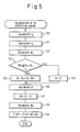
- FIG. 5 shows the calculation routine in the case of finding the HC deposition amount entirely by calculation
- FIG. 6 shows the calculation routine in the case of finding the HC deposition amount from the detection value of the HC concentration sensor 47.
- Each calculation routine is executed by interruption every predetermined time interval.
- the exhaust HC amount G O exhausted from the engine per unit time is calculated.
- the exhaust HC amount G O changing in accordance with this engine operating state is stored in the ROM 32.
- the HC feed amount G I fed from the HC feed valve 28 to raise the temperature of the NO x selective reduction catalyst 15 is calculated.
- the oxidation rate M O shown in FIG. 3 is calculated based on the bed temperature T O of the oxidation catalyst 12.
- step 55 the routine proceeds to step 55 where the pass-thru amount G is made zero, then the routine proceeds to step 56.
- the routine proceeds to step 55 where the pass-thru amount G is made G O +G I -M O , then the routine proceeds to step 56.
- the HC deposition rate R shown in FIG. 4(A) is calculated.
- the desorption rate Md shown in FIG. 4(B) is calculated based on the bed temperature Tn of the NO x selective reduction catalyst 15, next, at step 59, the new HC deposition amount W is added to the HC deposition amount ⁇ HC and the desorption rate Md is subtracted from the HC deposition amount ⁇ HC to calculate the HC deposition amount ⁇ HC.
- the amount (G O +G I ) of HC flowing into the NO x selective reduction catalyst 15 is calculated, and the HC deposition estimating means estimates the HC deposition amount ⁇ HC using the HC deposition rate R to the NO x selective reduction catalyst 15 preset for the calculated inflowing HC amount (G O +G I ) and the HC desorption rate Md from the NO x selective reduction catalyst 15.
- the HC concentration in the exhaust gas flowing into the NO x selective reduction catalyst 15 is detected by the HC concentration sensor 47.
- the amount G of HC flowing into the NO x selective reduction catalyst 15 per unit time is calculated based on the HC concentration detected by the HC concentration sensor 47 and the exhaust gas amount, that is, the intake air amount detected by the input air amount detector 8.
- the HC deposition rate R shown in FIG. 4(A) is calculated.
- the desorption rate MD shown in FIG. 4(B) is calculated based on the bed temperature Tn of the NO x selective reduction catalyst 15, next, at step 65, the new HC deposition amount W is added to the HC deposition amount ⁇ HC and the desorption rate Md is subtracted from the HC deposition amount ⁇ HC to calculate the HC deposition amount ⁇ HC.
- the HC concentration sensor 47 for detecting the HC concentration in the exhaust gas flowing into the NO x selective reduction catalyst 15 is provided, and the amount G of HC flowing into the NO x selective reduction catalyst 15 is formed by this HC concentration sensor 47.
- the HC deposition estimating means estimates the HC deposition amount ⁇ HC using the HC deposition rate R to the NO x selective reduction catalyst 15 preset for the found inflowing HC amount G and the HC desorption rate Md from the NO x selective reduction catalyst 15.
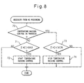
- the HC deposition amount ⁇ HC is found during engine operation in this way. Temperature raising control is performed based on this HC deposition amount ⁇ HC to restore the NO x selective reduction catalyst 15 from HC poisoning. That is, as shown in FIG. 7 , when the HC deposition amount ⁇ HC exceeds a predetermined allowable deposition amount MAX, the temperature raising control of the NO x selective reduction catalyst 15 is started. When the HC deposition amount ⁇ HC falls to a predetermined lower limit value MIN after starting to raise the temperature of the NO x selective reduction catalyst 15, the temperature raising action of the NO x selective reduction catalyst 15 is stopped.
- FIG. 8 shows the routine for recovery from HC poisoning. This routine is executed by interruption every predetermined time interval.
- step 70 it is judged if the temperature raising control is in progress.
- the routine proceeds to step 71 where it is judged if the HC deposition amount ⁇ HC exceeds the allowable deposition amount MAX.
- ⁇ HC>MAX the routine proceeds to step 72 where the temperature raising control is started.
- the routine proceeds from step 70 to step 73 where it is judged if the HC deposition amount ⁇ HC becomes less than the lower limit value MIN.
- ⁇ HC ⁇ MIN the routine proceeds to step 74 where the temperature raising control is stopped.
Landscapes
- Engineering & Computer Science (AREA)
- Chemical & Material Sciences (AREA)
- Chemical Kinetics & Catalysis (AREA)
- Combustion & Propulsion (AREA)
- Mechanical Engineering (AREA)
- General Engineering & Computer Science (AREA)
- Health & Medical Sciences (AREA)
- Toxicology (AREA)
- Materials Engineering (AREA)
- Biomedical Technology (AREA)
- Environmental & Geological Engineering (AREA)
- Analytical Chemistry (AREA)
- General Chemical & Material Sciences (AREA)
- Oil, Petroleum & Natural Gas (AREA)
- Exhaust Gas After Treatment (AREA)
- Exhaust Gas Treatment By Means Of Catalyst (AREA)
Applications Claiming Priority (2)
| Application Number | Priority Date | Filing Date | Title |
|---|---|---|---|
| JP2007206932A JP4730352B2 (ja) | 2007-08-08 | 2007-08-08 | 圧縮着火式内燃機関の排気浄化装置 |
| PCT/JP2008/063806 WO2009020053A1 (ja) | 2007-08-08 | 2008-07-25 | 内燃機関の排気浄化装置 |
Publications (2)
| Publication Number | Publication Date |
|---|---|
| EP2177731A1 true EP2177731A1 (de) | 2010-04-21 |
| EP2177731A4 EP2177731A4 (de) | 2011-04-27 |
Family
ID=40341287
Family Applications (1)
| Application Number | Title | Priority Date | Filing Date |
|---|---|---|---|
| EP08792019A Withdrawn EP2177731A4 (de) | 2007-08-08 | 2008-07-25 | Abgasreinigungsvorrichtung für verbrennungsmotor |
Country Status (5)
| Country | Link |
|---|---|
| US (1) | US20100058741A1 (de) |
| EP (1) | EP2177731A4 (de) |
| JP (1) | JP4730352B2 (de) |
| CN (1) | CN101600864A (de) |
| WO (1) | WO2009020053A1 (de) |
Families Citing this family (14)
| Publication number | Priority date | Publication date | Assignee | Title |
|---|---|---|---|---|
| JP2013002314A (ja) * | 2011-06-14 | 2013-01-07 | Hino Motors Ltd | 排気浄化装置 |
| JP5641360B2 (ja) * | 2011-12-08 | 2014-12-17 | トヨタ自動車株式会社 | 排ガス浄化用触媒及びその利用 |
| JP2014118945A (ja) * | 2012-12-19 | 2014-06-30 | Mitsubishi Motors Corp | 内燃機関の排気浄化装置 |
| EP2940265A4 (de) * | 2012-12-26 | 2015-12-23 | Toyota Motor Co Ltd | Abgasreinigungssystem für verbrennungsmotor |
| US9810124B2 (en) | 2013-04-05 | 2017-11-07 | Toyota Jidosha Kabushiki Kaisha | Exhaust gas purification system of internal combustion engine |
| US20140331644A1 (en) * | 2013-05-08 | 2014-11-13 | Cummins Ip, Inc. | Exhaust aftertreatment component condition estimation and regeneration |
| JP6149686B2 (ja) * | 2013-10-25 | 2017-06-21 | いすゞ自動車株式会社 | Scr触媒のhc吸着被毒検出システム及びscr触媒のhc吸着被毒検出方法 |
| JP2015105633A (ja) * | 2013-12-02 | 2015-06-08 | 日野自動車株式会社 | 排気浄化装置 |
| WO2015163892A1 (en) * | 2014-04-24 | 2015-10-29 | Cummins Inc. | Cylinder deactivation for catalyst drying |
| JP6248807B2 (ja) * | 2014-05-22 | 2017-12-20 | いすゞ自動車株式会社 | 排気ガスの後処理装置の機能回復方法及び排気ガスの後処理装置並びに内燃機関 |
| JP6179505B2 (ja) | 2014-12-24 | 2017-08-16 | トヨタ自動車株式会社 | 内燃機関の排気浄化システム |
| JP6179572B2 (ja) | 2015-09-11 | 2017-08-16 | トヨタ自動車株式会社 | 内燃機関の排気浄化システム |
| JP6551322B2 (ja) * | 2016-06-17 | 2019-07-31 | 株式会社デンソー | 浄化制御装置 |
| JP6707289B2 (ja) * | 2016-09-23 | 2020-06-10 | 日野自動車株式会社 | 選択還元型触媒の再生方法 |
Family Cites Families (5)
| Publication number | Priority date | Publication date | Assignee | Title |
|---|---|---|---|---|
| US6892530B2 (en) * | 2002-11-21 | 2005-05-17 | Ford Global Technologies, Llc | Exhaust gas aftertreatment systems |
| US6871489B2 (en) * | 2003-04-16 | 2005-03-29 | Arvin Technologies, Inc. | Thermal management of exhaust systems |
| JP4224383B2 (ja) | 2003-06-12 | 2009-02-12 | 日野自動車株式会社 | 排気浄化装置 |
| US6973776B2 (en) * | 2003-11-03 | 2005-12-13 | Ford Global Technologies, Llc | Exhaust gas aftertreatment systems |
| JP4826944B2 (ja) * | 2006-05-26 | 2011-11-30 | 株式会社豊田中央研究所 | ディーゼル排ガス浄化用構造体及びそれを用いた排ガス浄化方法 |
-
2007
- 2007-08-08 JP JP2007206932A patent/JP4730352B2/ja not_active Expired - Fee Related
-
2008
- 2008-07-25 EP EP08792019A patent/EP2177731A4/de not_active Withdrawn
- 2008-07-25 WO PCT/JP2008/063806 patent/WO2009020053A1/ja not_active Ceased
- 2008-07-25 CN CNA2008800038552A patent/CN101600864A/zh active Pending
- 2008-07-25 US US12/312,285 patent/US20100058741A1/en not_active Abandoned
Non-Patent Citations (2)
| Title |
|---|
| No further relevant documents disclosed * |
| See also references of WO2009020053A1 * |
Also Published As
| Publication number | Publication date |
|---|---|
| WO2009020053A1 (ja) | 2009-02-12 |
| JP2009041437A (ja) | 2009-02-26 |
| JP4730352B2 (ja) | 2011-07-20 |
| US20100058741A1 (en) | 2010-03-11 |
| EP2177731A4 (de) | 2011-04-27 |
| CN101600864A (zh) | 2009-12-09 |
Similar Documents
| Publication | Publication Date | Title |
|---|---|---|
| EP2177731A1 (de) | Abgasreinigungsvorrichtung für verbrennungsmotor | |
| CN101548077B (zh) | 内燃机的排气净化装置 | |
| US8516808B2 (en) | Exhaust purification device of internal combustion engine | |
| US8117834B2 (en) | Exhaust purification device of internal combustion engine | |
| CN101548074B (zh) | 内燃机的排气净化装置 | |
| EP2123875B1 (de) | Abgasreinigungsvorrichtung für einen kompressionsgezündeten verbrennungsmotor | |
| JP4729631B2 (ja) | 内燃機関の排気浄化装置 | |
| JP2009264181A (ja) | 内燃機関の排気浄化装置 | |
| JP2009257226A (ja) | 内燃機関の排気浄化装置 | |
| JP4821737B2 (ja) | 内燃機関の排気浄化装置 | |
| JP2009257231A (ja) | 内燃機関の排気浄化装置 | |
| EP2264291B1 (de) | Abgasreinigungssystem für verbrennungsmotor | |
| JP2010249076A (ja) | 内燃機関の排気浄化装置 | |
| JP2009167940A (ja) | 内燃機関の排気浄化装置 | |
| JP4595926B2 (ja) | 内燃機関の排気浄化装置 | |
| JP5052208B2 (ja) | 内燃機関の排気浄化装置 | |
| JP2008232055A (ja) | 内燃機関の排気浄化装置 | |
| JP4760661B2 (ja) | 内燃機関の排気浄化装置 | |
| JP2008255942A (ja) | 内燃機関の排気浄化装置 |
Legal Events
| Date | Code | Title | Description |
|---|---|---|---|
| PUAI | Public reference made under article 153(3) epc to a published international application that has entered the european phase |
Free format text: ORIGINAL CODE: 0009012 |
|
| 17P | Request for examination filed |
Effective date: 20100308 |
|
| AK | Designated contracting states |
Kind code of ref document: A1 Designated state(s): AT BE BG CH CY CZ DE DK EE ES FI FR GB GR HR HU IE IS IT LI LT LU LV MC MT NL NO PL PT RO SE SI SK TR |
|
| AX | Request for extension of the european patent |
Extension state: AL BA MK RS |
|
| DAX | Request for extension of the european patent (deleted) | ||
| A4 | Supplementary search report drawn up and despatched |
Effective date: 20110330 |
|
| GRAP | Despatch of communication of intention to grant a patent |
Free format text: ORIGINAL CODE: EPIDOSNIGR1 |
|
| STAA | Information on the status of an ep patent application or granted ep patent |
Free format text: STATUS: THE APPLICATION IS DEEMED TO BE WITHDRAWN |
|
| 18D | Application deemed to be withdrawn |
Effective date: 20120403 |