EP2177796A2 - Dispositif de soupape tubulaire - Google Patents
Dispositif de soupape tubulaire Download PDFInfo
- Publication number
- EP2177796A2 EP2177796A2 EP09012694A EP09012694A EP2177796A2 EP 2177796 A2 EP2177796 A2 EP 2177796A2 EP 09012694 A EP09012694 A EP 09012694A EP 09012694 A EP09012694 A EP 09012694A EP 2177796 A2 EP2177796 A2 EP 2177796A2
- Authority
- EP
- European Patent Office
- Prior art keywords
- valve
- valve seat
- closure member
- seat ring
- ring
- Prior art date
- Legal status (The legal status is an assumption and is not a legal conclusion. Google has not performed a legal analysis and makes no representation as to the accuracy of the status listed.)
- Granted
Links
Images
Classifications
-
- F—MECHANICAL ENGINEERING; LIGHTING; HEATING; WEAPONS; BLASTING
- F16—ENGINEERING ELEMENTS AND UNITS; GENERAL MEASURES FOR PRODUCING AND MAINTAINING EFFECTIVE FUNCTIONING OF MACHINES OR INSTALLATIONS; THERMAL INSULATION IN GENERAL
- F16K—VALVES; TAPS; COCKS; ACTUATING-FLOATS; DEVICES FOR VENTING OR AERATING
- F16K31/00—Actuating devices; Operating means; Releasing devices
- F16K31/02—Actuating devices; Operating means; Releasing devices electric; magnetic
- F16K31/06—Actuating devices; Operating means; Releasing devices electric; magnetic using a magnet, e.g. diaphragm valves, cutting off by means of a liquid
- F16K31/0644—One-way valve
- F16K31/0651—One-way valve the fluid passing through the solenoid coil
-
- F—MECHANICAL ENGINEERING; LIGHTING; HEATING; WEAPONS; BLASTING
- F16—ENGINEERING ELEMENTS AND UNITS; GENERAL MEASURES FOR PRODUCING AND MAINTAINING EFFECTIVE FUNCTIONING OF MACHINES OR INSTALLATIONS; THERMAL INSULATION IN GENERAL
- F16K—VALVES; TAPS; COCKS; ACTUATING-FLOATS; DEVICES FOR VENTING OR AERATING
- F16K1/00—Lift valves or globe valves, i.e. cut-off apparatus with closure members having at least a component of their opening and closing motion perpendicular to the closing faces
- F16K1/12—Lift valves or globe valves, i.e. cut-off apparatus with closure members having at least a component of their opening and closing motion perpendicular to the closing faces with streamlined valve member around which the fluid flows when the valve is opened
-
- F—MECHANICAL ENGINEERING; LIGHTING; HEATING; WEAPONS; BLASTING
- F16—ENGINEERING ELEMENTS AND UNITS; GENERAL MEASURES FOR PRODUCING AND MAINTAINING EFFECTIVE FUNCTIONING OF MACHINES OR INSTALLATIONS; THERMAL INSULATION IN GENERAL
- F16K—VALVES; TAPS; COCKS; ACTUATING-FLOATS; DEVICES FOR VENTING OR AERATING
- F16K1/00—Lift valves or globe valves, i.e. cut-off apparatus with closure members having at least a component of their opening and closing motion perpendicular to the closing faces
- F16K1/12—Lift valves or globe valves, i.e. cut-off apparatus with closure members having at least a component of their opening and closing motion perpendicular to the closing faces with streamlined valve member around which the fluid flows when the valve is opened
- F16K1/123—Lift valves or globe valves, i.e. cut-off apparatus with closure members having at least a component of their opening and closing motion perpendicular to the closing faces with streamlined valve member around which the fluid flows when the valve is opened with stationary valve member and moving sleeve
-
- Y—GENERAL TAGGING OF NEW TECHNOLOGICAL DEVELOPMENTS; GENERAL TAGGING OF CROSS-SECTIONAL TECHNOLOGIES SPANNING OVER SEVERAL SECTIONS OF THE IPC; TECHNICAL SUBJECTS COVERED BY FORMER USPC CROSS-REFERENCE ART COLLECTIONS [XRACs] AND DIGESTS
- Y10—TECHNICAL SUBJECTS COVERED BY FORMER USPC
- Y10T—TECHNICAL SUBJECTS COVERED BY FORMER US CLASSIFICATION
- Y10T137/00—Fluid handling
- Y10T137/3367—Larner-Johnson type valves; i.e., telescoping internal valve in expanded flow line section
-
- Y—GENERAL TAGGING OF NEW TECHNOLOGICAL DEVELOPMENTS; GENERAL TAGGING OF CROSS-SECTIONAL TECHNOLOGIES SPANNING OVER SEVERAL SECTIONS OF THE IPC; TECHNICAL SUBJECTS COVERED BY FORMER USPC CROSS-REFERENCE ART COLLECTIONS [XRACs] AND DIGESTS
- Y10—TECHNICAL SUBJECTS COVERED BY FORMER USPC
- Y10T—TECHNICAL SUBJECTS COVERED BY FORMER US CLASSIFICATION
- Y10T137/00—Fluid handling
- Y10T137/8593—Systems
- Y10T137/86928—Sequentially progressive opening or closing of plural valves
-
- Y—GENERAL TAGGING OF NEW TECHNOLOGICAL DEVELOPMENTS; GENERAL TAGGING OF CROSS-SECTIONAL TECHNOLOGIES SPANNING OVER SEVERAL SECTIONS OF THE IPC; TECHNICAL SUBJECTS COVERED BY FORMER USPC CROSS-REFERENCE ART COLLECTIONS [XRACs] AND DIGESTS
- Y10—TECHNICAL SUBJECTS COVERED BY FORMER USPC
- Y10T—TECHNICAL SUBJECTS COVERED BY FORMER US CLASSIFICATION
- Y10T137/00—Fluid handling
- Y10T137/8593—Systems
- Y10T137/87917—Flow path with serial valves and/or closures
Definitions
- the invention relates to a valve in tube form and a method for releasing and blocking a fluid flow with such a valve.
- valves have a valve housing and at least one valve closure element arranged therein.
- the valve closure member is linearly reciprocable with respect to a valve seat to controllably close or release the valve seat.
- the armature moves the valve closure member against the force of a closing spring away from the valve seat.
- Such valves have self-closing function. When dimensioning the magnetic drive, care is taken that it is able to overcome the force of the closing spring. This often leads to relatively large and correspondingly in need of magnetic drives.
- valve closure member via an engine control unit.
- the linear actuating movement for the valve closure member is generated from the rotational movement of the motor, for example via a screw jack.
- the self-closing function is usually provided by closing springs in the former case, the traction magnet and the motor drive from the open position to the closed position drove accordingly strong-sized closing springs can be a shock-like, hard placement of the valve closure member on the valve seat and with time there to damage to lead.
- valve according to the invention has a tubular housing in which at least one, for example, sleeve-shaped valve seat ring is disposed axially movable.
- at least one, for example, sleeve-shaped valve seat ring is disposed axially movable.
- two such concentric valve seat rings are provided.
- a locking device serves to lock the valve seat rings selectively in a predetermined position and release, if necessary.
- the valve seat rings is associated with at least one valve closure member that is also movably mounted. It is movable toward and away from the valve seat rings to selectively close, displace or release the valve seat rings.
- An adjusting device for adjusting the position of the same is provided.
- Such a valve makes it possible to move the valve seat rings by means of the actuating device of the valve closure member. It can be used specifically to move the valve seat inserts in a locking position, in which they can be held by the locking device, the stelkl arthritis the valve closure member. Once the valve seating rings are locked in this position, the valve closure member can be moved away from the valve seat rings by actuation of the actuator to regulate the flow of gas or other fluid flow.
- the valve closure member can be used both for fine adjustment of the fluid flow as well as for easy opening and closing.
- the adjusting device is preferably designed so that the actuating speed of the valve closure member as well as its positioning is finely adjustable. For example, a stepper motor drive can be used to adjust the valve closure member.
- the locking device is to release at least one of the valve seat rings.
- the valve seating rings may be moved toward the valve gate by a suitable means such as spring means such as compression springs, tension springs, repelling permanent magnets, attracting permanent magnets, or the like to close the fluid path.
- the closing function is independent of the current position of the valve closure member.
- the quick-closing of the valve is done by unlocking at least a valve seat ring and displacement of at least one valve seat ring towards the valve closure member.
- the locking device can be formed in a particularly simple and energy-saving manner by a holding magnet, the tensile force of which does not have to be sufficient to overcome the closing spring. It is sufficient a holding force that is greater than the force of the closing spring.
- the holding magnet can be provided with a relatively weakly dimensioned holding coil.
- the copper cost is low. Correspondingly low are heat development and power consumption.
- the closing spring acts on the valve seat ring.
- the upcoming gas pressure produces only a small force acting on the valve seat ring.
- the effective effective area, which is acted upon by the gas pressure, is merely the end face of the valve seat ring.
- the inventive concept allows easily to combine the fine adjustment of a valve with finely positionable valve closure member with the quick-closing function of a on / off valve. This is achieved by the quick-closing function is assigned to the valve seat ring, while the fine adjustment is associated with the valve closure member.
- the closing of the valve can be done by releasing the locking device or while maintaining the lock by appropriately controlled detection of the valve closure member. In the latter case, the release of the locking device is used exclusively for safety shutdown.
- valve according to claim 2 provides the arrangement of the magnetic coil for locking the at least one valve seat ring in the housing. This has the advantage that the magnetic coil is cooled by the fluid flow flowing through the housing. This measure allows higher current densities in the solenoid and thus copper savings. Otherwise, all other advantages mentioned in connection with the valve according to claim 1 can also be achieved in the valve according to claim 2.
- valve according to claim 3 provides the aforementioned advantages. While the adjusting device for the valve closure member in the aforementioned embodiments may be formed in principle arbitrary, claim 3 provides the formation of the actuator for the valve closure member in a manner that receives the actuator a self-holding function.
- a self-locking transmission is provided between a drive, for example a motor, and the valve closure member.
- a transmission may be a screw jack, a worm gear or the like or more such gear in combination.
- the drive is preferably an electric motor for the adjusting device.
- This can be designed as a stepper motor, DC motor, synchronous motor, asynchronous motor or the like. It can be arranged both inside the tubular housing and outside it.
- the valve according to the invention allows the use of particularly energy-efficient drives.
- the tubular housing can be provided at its ends with threads, flanges or other connection means.
- a leak test can be made. This is especially true when the two valve seat rings are sealed against each other to define a trapped between the valve seat center space to which a pressure monitor is connected.
- the valve concept leads to valves that are functional regardless of the installation position.
- the concept is also suitable for a pressure range from 0 to several bar and thus for many applications with different customers.
- the valve can be operated quietly. Opening and closing noises are minimized.
- the fluid flow can be continuously modulated. It also relies on few components and is easily adaptable to different applications.
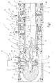
- a valve 1 which has a tubular housing 2, for example as a gas valve, for example, also serves as a gas safety valve.
- the housing 2 is provided at its two ends facing away from each other with not further illustrated connecting means for connecting further tubes and, for example, seals 3, 4.
- a fluid channel 5 is fixed, which leads from one end to the other end.
- the fluid channel 5 is delimited on the input side by a tubular guide piece 6 that is fixed in position and concentric with a central axis 8 by a ring 7 in the housing 2.
- the ring 7 has at its preferably cylindrical outer circumference at least one or more circumferential grooves, in which seals 9, 10 may be housed to seal the ring 7 in the axial direction against the inner wall of the tubular housing 2.
- a screw 11 may be provided to secure the ring 7 stationary.
- the insert 6 has a tubular lip 12 which extends away from the open end insert 6 into the interior of the housing 2 inside.
- the insert 6 is provided with a fastening device, for example in the form of latching fingers 13, which cause an axial securing of the insert 6 to the ring 7 and engage there, for example, in a groove.
- the fluid channel 5 is delimited by an elongated tubular valve seat ring 14. This is mounted axially displaceable and formed as a sleeve. It is centered by two axially spaced guide rings 15, 16 in the tubular housing 2 to the central axis 8.
- the sleeve 12 of the Leit Vietnamesees 6 extends into the interior of the valve seat ring 14 and is on the wall of the same slidably when the valve seat ring 14 is axially displaced.
- the guide ring 16 is sealed by means of the central axis 8 concentric seals 17, 18 against the inner wall of the housing 2 and secured by a screw 19 non-rotatable and axially fixed.
- On its inside it carries a sliding ring 20 which supports the valve seat ring 14 easily displaceable.
- a seal for example in the form of a lip seal 21, which seals the guide ring 16 against the valve seat ring 14 in a gas-tight manner in the axial direction.
- the guide piece 6 facing the end of the valve seat ring 14 is provided with a soft magnetic anchor ring 22. This is axially movable together with the valve seat ring 14.
- a compression spring 23 biases the valve seat ring 14 and the anchor ring 22 while the ring 17 away.
- the ring 17 consists for example of soft magnetic material. In particular, it may be provided on its side facing the anchor ring 22 with a groove which houses a winding 24.
- the windings of the winding 24 are preferably arranged concentrically to the central axis 8.
- valve seat ring 26 concentric with the first valve seat ring 14 is a second valve seat ring 26 which is concentric with the first valve seat ring 14 and surrounds its outer surface.
- the valve seat ring 26 is formed as a sleeve and is seated in the guide ring 15, which has one or more slide rings 27, 28. These allow a slight axial displacement of the valve seat ring 26 against the guide ring 15 and against the inner valve seat ring 14. between the valve seat rings 14, 26, a further slide ring 29 may be arranged, which is connected for example to the valve seat ring 14 or alternatively to the valve seat ring 26.
- the guide ring 15 is seated by means of seals 30, 31 sealed and secured by at least one screw 32 fixed in the housing 2. He has inside an annular groove in which a lip seal 33 is seated. This seals the second valve seat ring 26 from the outside gas-tight.
- the second tubular valve seat ring 26 is axially movable against the force of a compression spring 34.
- the compression spring 34 is supported at one end on the guide ring 16 and at the other end on the valve seat ring 26 from. This is connected at the same end with a disc-shaped anchor ring 35 which is displaceable together with the valve seat ring 26 against the force of the compression spring 34 on the guide ring 16.
- the guide ring 16 has on the armature ring 35 side facing an annular groove in which a winding 36 is seated. The turns of this winding 36 are concentric oriented to the central axis 18.
- the guide ring 16 may be made of a soft magnetic material.
- the dimensioning of the anchor ring 35 and the winding 36 and the guide ring 16 is dimensioned so that the winding 36, when energized, can hold the anchor ring 35 on the guide ring 16. This position is in FIG. 1 illustrated below. In FIG. 1 above, the position of the valve seat ring 26 and the anchor ring 35 in the de-energized state of the winding 36 is illustrated. The winding 36, together with the anchor ring 35, forms a locking device for the second valve seat ring 26.
- Both valve seat rings 14, 26 have at their from the respective anchor rings 22, 35 facing away from sealing surfaces 37, 38, which are formed for example as a conical annular surfaces. These sealing surfaces 37, 38 form the actual valve seat. Inside a valve closure member 39 is associated with that, as shown, may be formed as a flow body. His peak is preferably approximately on the central axis 8. From there starting, the valve closure member 39 is conical, teardrop-shaped or otherwise aerodynamically formed. It has in the present embodiment, two ring seals 40, 41, which are arranged concentrically to the central axis 8. Their diameter is dimensioned so that they can come into contact with the sealing surfaces 37, 38. For example, they have a rectangular cross-section and are partially embedded in the valve closure member 39.
- the valve closure member 39 is arranged axially adjustable along the central axis 8. Serves any suitable actuator.
- the valve closure member 39 is in FIG. 1 shown above in its left-side extreme position in which it has the greatest possible distance from the guide ring 15. In FIG. 1 below it is shown in its extreme right-hand position in which it has the greatest possible approximation to the guide ring 15.
- the maximum stroke of the valve closure member 39 is at least as large as the maximum stroke of the two valve seat rings 14, 26th
- the valve closure member 39 is on its rear side facing away from its tip, cup-shaped and provided with a threaded spindle 42. This dips into the bore of a guide body 43, which is held at a distance from the inner wall of the housing 2 centric to the central axis 8. For game clearance, a compression spring may be provided which urges the valve closure member 39 in the closing direction.
- the guide body 43 has at least one, preferably a plurality, for example, three radial projections 44, which protrude away from it like spokes and bear against the inner surface of the housing 2 on the inside. A arranged in such a radial extension 44 threaded bore can serve to receive a fastening screw 45, with which the guide body 43 is secured axially stationary.
- the guide body 43 has an inner space in which a threaded nut 46 between two thrust bearings 47, 48 is rotatably mounted.
- the threaded nut 46 has an internal thread, and is screwed to the threaded spindle 42. Rotation of the threaded nut 46 therefore causes an adjustment of the threaded spindle 42 and thus the valve closure member 39 in the direction of the arrow 49 or 50th
- the threaded nut 46 is externally provided with a toothing. It meshes with a worm 51 which is arranged tangentially to the gear formed by the threaded nut 46 and is rotatably mounted.
- the screw 51 passes through the guide body 43 and the radial extension 44. Through an opening of the housing 2, it protrudes to the outside.
- Another sealing means for example an 8-shaped rubber seal 53, which may be arranged in a correspondingly shaped groove of the radial extension 44, also seals both the threaded bore of the fastening screw 45 as well as the through hole for the screw 52 to the outside.
- the outwardly projecting end of the worm 51 may be connected to a rotary drive, such as a stepper motor or other motor 54. Its electrical connections 55 are in FIG. 1 merely symbolically illustrated.
- the motor 54 is connected to the housing 2 via a holder (not further illustrated).
- pressure measuring ports 56, 57 may be provided on the housing 2 individually or in conjunction with each other.
- the pressure port 56 measures the downstream pressure.
- the pressure port 58 allows the upstream pressure measurement.
- the pressure port 57 allows the measurement of the pressure between the two valve seats 14, 26.
- the described valve 1 is a double seat valve.
- the connection 57 leads into the so-called middle space between the two individual valves.
- the first valve is formed by the valve seat ring 14 and the ring seal 40.
- the second valve is formed by the valve seat ring 26 and the ring seal 41.
- the valve 1 described so far operates as follows:
- valve 1 is de-energized. Neither the winding 24, nor the winding 36 carries electricity.
- the valve seat rings 14 26 are displaced by the associated compression springs 23, 34 in each case as far as possible in the direction of the valve closure member 39.
- the sealing surfaces 37, 38 are applied to the ring seals 40 41.
- the gas flow through the fluid channel 5 is independent of the position of the valve closure member 39 is blocked. If it is in a left position, like it FIG. 1 As illustrated above, the valve is closed as well as when it is in a right position, as in FIG FIG. 1 illustrated below.
- valve closure member 39 is moved by appropriate control of the motor 54 so that the valve seat rings 14, 26 are shifted to the windings 24, 36, unless it already occupies this position anyway.
- the threaded nut 46 is rotated in such a direction that the threaded spindle 42 moves in the direction of the arrow 49.
- the valve closure member 39 thereby displaces the valve seat rings 14, 26 from the in FIG. 1 upper position in the in FIG. 1 shown below position in which the anchor rings 22, 35 abut the ring 7 and the guide ring 16.
- An energization of the windings 24, 36 now causes the anchor rings 22, 35 adhere to the rings 7, 16.
- the compression springs 23, 34 are sized in their strength so that they can not overcome this adhesive force.
- the valve seat rings 14, 26 are thereby locked in a position in which the valve can be opened by adjusting the valve closure member 39.
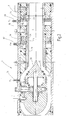
- valve closure member 39 in the in FIG. 1 When the valve closure member 39 in the in FIG. 1 is shown below, the valve 1 has a rest position. From this, it can be opened immediately by the windings 24, 26 and the motor 54 are energized, so that the motor 54, the threaded spindle 42 moves in the direction of the arrow 50. As a result, the valve 1 enters the in FIG. 2 illustrated state.
- the valve closure member 39 releases the valve seats, while the windings 24, 36 due to the flow of current, the valve seat rings 14, 26 in the release position according to FIG. 2 hold.
- the valve closure member 39 can now be arbitrarily adjusted to completely release a gas flow through the fluid channel 5 or more or less to throttle. It can also be reset to zero when the valve closure member 39 is moved to the closed position.
- valve 1 thus meets both low safety and low design both safety function with quick-closing characteristic and a modulation function.
- a tightness test can be easily made by the pressure in the Middle space is monitored via the port 57.
- close only one valve of this double valve arrangement This can be done, for example, by initially both valve seat rings 14, 26 in the locking position according to FIG. 2 brought and held there, whereupon the valve closure member 39 is in the open position and the locking position for only one of the two valve seat rings 14, 26 or the locking of the two valve seat rings 14, 26 is successively solved. If, for example, first the locking of the valve seat ring 14 and then the locking of the valve seat ring 26 is released, the pressure at the connection 57 must match the pressure at the connection 56.
- valve of the valve seat ring 14 is leaking. Conversely, the pressure at port 57 must match the pressure at port 58 when first winding 36 and then winding 24 de-energize. The volume of gas trapped in the central space has the inlet pressure. If this gradually falls, the valve of the valve seat ring 36 is leaking.
- the presented valve 1 is based on two axially adjustable sleeve-shaped valve seat rings 14, 26, which locking devices in the form of annular anchor plates 22, 35 and associated holding windings 24, 36 are assigned.
- the valve closure member 39 is variably adjustable via a position actuator. It has a double function. It serves, on the one hand, to transfer the valve seat rings 14, 26 into the locking position and, on the other hand, to regulate the gas flow.
Landscapes
- Engineering & Computer Science (AREA)
- General Engineering & Computer Science (AREA)
- Mechanical Engineering (AREA)
- Physics & Mathematics (AREA)
- Fluid Mechanics (AREA)
- Magnetically Actuated Valves (AREA)
- Lift Valve (AREA)
Applications Claiming Priority (1)
| Application Number | Priority Date | Filing Date | Title |
|---|---|---|---|
| DE200810051759 DE102008051759B3 (de) | 2008-10-15 | 2008-10-15 | Rohrförmige Ventileinrichtung |
Publications (3)
| Publication Number | Publication Date |
|---|---|
| EP2177796A2 true EP2177796A2 (fr) | 2010-04-21 |
| EP2177796A3 EP2177796A3 (fr) | 2010-08-04 |
| EP2177796B1 EP2177796B1 (fr) | 2012-10-24 |
Family
ID=41600387
Family Applications (1)
| Application Number | Title | Priority Date | Filing Date |
|---|---|---|---|
| EP20090012694 Active EP2177796B1 (fr) | 2008-10-15 | 2009-10-07 | Dispositif de soupape tubulaire |
Country Status (4)
| Country | Link |
|---|---|
| US (1) | US8286937B2 (fr) |
| EP (1) | EP2177796B1 (fr) |
| CN (1) | CN101725716B (fr) |
| DE (1) | DE102008051759B3 (fr) |
Cited By (17)
| Publication number | Priority date | Publication date | Assignee | Title |
|---|---|---|---|---|
| US20150069279A1 (en) * | 2012-04-16 | 2015-03-12 | Danfoss A/S | Axial valve |
| US9645584B2 (en) | 2014-09-17 | 2017-05-09 | Honeywell International Inc. | Gas valve with electronic health monitoring |
| US9657946B2 (en) | 2012-09-15 | 2017-05-23 | Honeywell International Inc. | Burner control system |
| US9683674B2 (en) | 2013-10-29 | 2017-06-20 | Honeywell Technologies Sarl | Regulating device |
| US9835265B2 (en) | 2011-12-15 | 2017-12-05 | Honeywell International Inc. | Valve with actuator diagnostics |
| US9841122B2 (en) | 2014-09-09 | 2017-12-12 | Honeywell International Inc. | Gas valve with electronic valve proving system |
| US9846440B2 (en) | 2011-12-15 | 2017-12-19 | Honeywell International Inc. | Valve controller configured to estimate fuel comsumption |
| US9851103B2 (en) | 2011-12-15 | 2017-12-26 | Honeywell International Inc. | Gas valve with overpressure diagnostics |
| US9995486B2 (en) | 2011-12-15 | 2018-06-12 | Honeywell International Inc. | Gas valve with high/low gas pressure detection |
| US10024439B2 (en) | 2013-12-16 | 2018-07-17 | Honeywell International Inc. | Valve over-travel mechanism |
| US10422531B2 (en) | 2012-09-15 | 2019-09-24 | Honeywell International Inc. | System and approach for controlling a combustion chamber |
| US10503181B2 (en) | 2016-01-13 | 2019-12-10 | Honeywell International Inc. | Pressure regulator |
| US10564062B2 (en) | 2016-10-19 | 2020-02-18 | Honeywell International Inc. | Human-machine interface for gas valve |
| US10697815B2 (en) | 2018-06-09 | 2020-06-30 | Honeywell International Inc. | System and methods for mitigating condensation in a sensor module |
| US10697632B2 (en) | 2011-12-15 | 2020-06-30 | Honeywell International Inc. | Gas valve with communication link |
| US11073281B2 (en) | 2017-12-29 | 2021-07-27 | Honeywell International Inc. | Closed-loop programming and control of a combustion appliance |
| DE102020202908A1 (de) | 2020-03-06 | 2021-09-09 | Robert Bosch Gesellschaft mit beschränkter Haftung | Strömungskanal zur Durchströmung mit einem Gas |
Families Citing this family (19)
| Publication number | Priority date | Publication date | Assignee | Title |
|---|---|---|---|---|
| EP2384407B1 (fr) * | 2009-03-16 | 2017-02-15 | Artemis Intelligent Power Limited | Vannes contrôlées électroniquement |
| EP2463558A1 (fr) * | 2010-12-07 | 2012-06-13 | TA Hydronics S.A. | Améliorations de l'équilibrage et vannes de contrôle |
| US8839815B2 (en) | 2011-12-15 | 2014-09-23 | Honeywell International Inc. | Gas valve with electronic cycle counter |
| US9074770B2 (en) | 2011-12-15 | 2015-07-07 | Honeywell International Inc. | Gas valve with electronic valve proving system |
| US8947242B2 (en) | 2011-12-15 | 2015-02-03 | Honeywell International Inc. | Gas valve with valve leakage test |
| US8905063B2 (en) | 2011-12-15 | 2014-12-09 | Honeywell International Inc. | Gas valve with fuel rate monitor |
| US8899264B2 (en) | 2011-12-15 | 2014-12-02 | Honeywell International Inc. | Gas valve with electronic proof of closure system |
| US10415708B2 (en) * | 2013-11-04 | 2019-09-17 | Sang Jin Choi | Cone valve and manufacturing method thereof |
| DE102015122033A1 (de) * | 2015-12-16 | 2017-06-22 | Khs Gmbh | Fülleinrichtung |
| DE102016112413B4 (de) * | 2016-07-06 | 2022-05-25 | Pierburg Gmbh | Axial durchströmbares Fluidventil |
| DE102016112410B4 (de) * | 2016-07-06 | 2022-10-20 | Pierburg Gmbh | Axial durchströmbares Fluidventil |
| CN107035905A (zh) * | 2017-05-25 | 2017-08-11 | 大禹节水集团股份有限公司 | 一种用于低压灌溉的压力流量调节器 |
| US10900585B2 (en) * | 2019-02-18 | 2021-01-26 | Automatic Switch Company | Coaxial valves |
| US10823308B1 (en) * | 2019-06-20 | 2020-11-03 | Hamilton Sunstrand Corporation | Controllers for inline valves, inline valves, and methods of controlling flow through inline valves |
| US10823087B1 (en) * | 2019-06-20 | 2020-11-03 | Hamilton Sunstrand Corporation | Inline valves, gas turbine engines with inline bleed valves, and methods controlling flow through inline valves |
| US10830372B1 (en) * | 2019-06-20 | 2020-11-10 | Hamilton Sunstrand Corporation | Pneumatic controllers, pneumatically controlled inline valves, and methods of cooling pneumatic controllers |
| US10824172B1 (en) * | 2019-06-20 | 2020-11-03 | Hamilton Sunstrand Corporation | Pneumatic controllers, pneumatically controlled inline valves, and methods of actuating inline valves |
| US11047484B2 (en) * | 2019-08-20 | 2021-06-29 | Mueller International, Llc | Fixed cone valve with dual seating system |
| DE202020103323U1 (de) | 2020-06-09 | 2021-09-16 | Gneuss Gmbh | Drosselventil für Kunststoffschmelzen und andere hochviskose Fluide |
Family Cites Families (25)
| Publication number | Priority date | Publication date | Assignee | Title |
|---|---|---|---|---|
| US684913A (en) * | 1901-02-25 | 1901-10-22 | James M Cordell | Valve. |
| US1147023A (en) * | 1914-08-27 | 1915-07-20 | Herman F Holmquest | Valve for gas-engines. |
| US1473634A (en) * | 1918-04-05 | 1923-11-13 | Vapor Car Heating Co Inc | Valve-operating mechanism |
| US1387446A (en) * | 1919-03-19 | 1921-08-16 | Astier Antoine Joseph | Valve for pipes for water and other fluids |
| US2852035A (en) * | 1953-09-04 | 1958-09-16 | Koppers Co Inc | Sealing device, in particular for the transfer of loose material into or out of gas-filled spaces |
| US2962039A (en) * | 1954-05-27 | 1960-11-29 | Shand Stanley Grapes | Fluid controlling valves |
| US3148859A (en) * | 1962-02-14 | 1964-09-15 | United Aircraft Corp | Liquid-metal valve |
| US3322138A (en) * | 1964-06-01 | 1967-05-30 | William O Backman | Packingless in-line valve |
| SE323556B (fr) * | 1968-04-18 | 1970-05-04 | Alfa Laval Ab | |
| US3605878A (en) * | 1969-10-08 | 1971-09-20 | Sanders Associates Inc | Heat pipe with variable evaporator |
| US3654950A (en) * | 1970-04-20 | 1972-04-11 | Borg Warner | Valve |
| US4077425A (en) * | 1973-06-14 | 1978-03-07 | Mordeki Drori | Fluid flow control devices |
| US4605035A (en) * | 1984-09-14 | 1986-08-12 | Lavrids Knudsen Maskinefabrik A/S | Double seat valve |
| DE3536947C1 (de) * | 1985-10-17 | 1987-04-09 | Rost & Soehne Georg | Druckspueler mit integrierter Vorabsperrung |
| US5826613A (en) * | 1993-05-19 | 1998-10-27 | Georg Fischer Rohrleitungssysteme Ag | Flow control valve |
| US6047766A (en) * | 1998-08-03 | 2000-04-11 | Hewlett-Packard Company | Multi-mode heat transfer using a thermal heat pipe valve |
| DE19964256B4 (de) * | 1998-08-03 | 2005-02-03 | Hewlett-Packard Company (N.D.Ges.D.Staates Delaware), Palo Alto | Ventil für eine Wärmeröhre |
| DE10062487C1 (de) * | 2000-12-14 | 2002-03-07 | Gruner Ag | Elektromagnetventil |
| US7066447B2 (en) * | 2001-04-18 | 2006-06-27 | Fisher Controls International Llc. | Sleeve valve with adjustable flow characteristics |
| DE10121616A1 (de) * | 2001-05-03 | 2002-11-07 | Mueller Co Ax Gmbh | Koaxialventil |
| US7004186B2 (en) * | 2003-06-30 | 2006-02-28 | The Boeing Company | Surge relief apparatus for a valve |
| DE20311032U1 (de) * | 2003-07-17 | 2004-11-25 | Cooper Cameron Corp., Houston | Antriebsvorrichtung |
| DE102004059926B3 (de) * | 2004-12-13 | 2006-08-10 | Weinhold, Karl, Dipl.-Ing. (FH) | Rückschlagventil mit unterschiedlichen Flussrichtungen |
| US7493912B2 (en) * | 2006-06-09 | 2009-02-24 | Hartman Brian T | Fixed cone sleeve valve having cone supported by means downstream of the gate in its closed position |
| DE202006018420U1 (de) * | 2006-12-04 | 2008-04-17 | Interforge Klee Gmbh | Absperrarmatur mit Längenausgleich |
-
2008
- 2008-10-15 DE DE200810051759 patent/DE102008051759B3/de not_active Expired - Fee Related
-
2009
- 2009-10-07 EP EP20090012694 patent/EP2177796B1/fr active Active
- 2009-10-13 US US12/587,736 patent/US8286937B2/en not_active Expired - Fee Related
- 2009-10-15 CN CN200910206366.3A patent/CN101725716B/zh not_active Expired - Fee Related
Cited By (22)
| Publication number | Priority date | Publication date | Assignee | Title |
|---|---|---|---|---|
| US9995486B2 (en) | 2011-12-15 | 2018-06-12 | Honeywell International Inc. | Gas valve with high/low gas pressure detection |
| US9835265B2 (en) | 2011-12-15 | 2017-12-05 | Honeywell International Inc. | Valve with actuator diagnostics |
| US10851993B2 (en) | 2011-12-15 | 2020-12-01 | Honeywell International Inc. | Gas valve with overpressure diagnostics |
| US9846440B2 (en) | 2011-12-15 | 2017-12-19 | Honeywell International Inc. | Valve controller configured to estimate fuel comsumption |
| US9851103B2 (en) | 2011-12-15 | 2017-12-26 | Honeywell International Inc. | Gas valve with overpressure diagnostics |
| US10697632B2 (en) | 2011-12-15 | 2020-06-30 | Honeywell International Inc. | Gas valve with communication link |
| US9334967B2 (en) * | 2012-04-16 | 2016-05-10 | Danfoss A/S | Axial valve |
| US20150069279A1 (en) * | 2012-04-16 | 2015-03-12 | Danfoss A/S | Axial valve |
| US11421875B2 (en) | 2012-09-15 | 2022-08-23 | Honeywell International Inc. | Burner control system |
| US9657946B2 (en) | 2012-09-15 | 2017-05-23 | Honeywell International Inc. | Burner control system |
| US10422531B2 (en) | 2012-09-15 | 2019-09-24 | Honeywell International Inc. | System and approach for controlling a combustion chamber |
| US9683674B2 (en) | 2013-10-29 | 2017-06-20 | Honeywell Technologies Sarl | Regulating device |
| US10215291B2 (en) | 2013-10-29 | 2019-02-26 | Honeywell International Inc. | Regulating device |
| US10024439B2 (en) | 2013-12-16 | 2018-07-17 | Honeywell International Inc. | Valve over-travel mechanism |
| US9841122B2 (en) | 2014-09-09 | 2017-12-12 | Honeywell International Inc. | Gas valve with electronic valve proving system |
| US10203049B2 (en) | 2014-09-17 | 2019-02-12 | Honeywell International Inc. | Gas valve with electronic health monitoring |
| US9645584B2 (en) | 2014-09-17 | 2017-05-09 | Honeywell International Inc. | Gas valve with electronic health monitoring |
| US10503181B2 (en) | 2016-01-13 | 2019-12-10 | Honeywell International Inc. | Pressure regulator |
| US10564062B2 (en) | 2016-10-19 | 2020-02-18 | Honeywell International Inc. | Human-machine interface for gas valve |
| US11073281B2 (en) | 2017-12-29 | 2021-07-27 | Honeywell International Inc. | Closed-loop programming and control of a combustion appliance |
| US10697815B2 (en) | 2018-06-09 | 2020-06-30 | Honeywell International Inc. | System and methods for mitigating condensation in a sensor module |
| DE102020202908A1 (de) | 2020-03-06 | 2021-09-09 | Robert Bosch Gesellschaft mit beschränkter Haftung | Strömungskanal zur Durchströmung mit einem Gas |
Also Published As
| Publication number | Publication date |
|---|---|
| EP2177796B1 (fr) | 2012-10-24 |
| EP2177796A3 (fr) | 2010-08-04 |
| DE102008051759B3 (de) | 2010-04-29 |
| US20100102259A1 (en) | 2010-04-29 |
| US8286937B2 (en) | 2012-10-16 |
| CN101725716A (zh) | 2010-06-09 |
| CN101725716B (zh) | 2014-07-30 |
Similar Documents
| Publication | Publication Date | Title |
|---|---|---|
| EP2177796B1 (fr) | Dispositif de soupape tubulaire | |
| DE102004004708B3 (de) | Magnetventil | |
| DE102007003707B4 (de) | Kolbenzylindereinheit | |
| DE19826076C1 (de) | Doppelsicherheitsventil | |
| DE102013106214B4 (de) | Kolbenschieberventil | |
| DE69509622T2 (de) | Elektromagnetventil für Bewässersteuerungseinheiten | |
| DE19805049A1 (de) | Elektromagnet | |
| DE68916435T2 (de) | Schnell ansprechendes, druckausgeglichenes, elektromagnetisches hochdruck-steuerventil. | |
| EP2405166B1 (fr) | Soupape électromagnétique | |
| DE19636781A1 (de) | Magnetventil | |
| EP3379120B1 (fr) | Dispositif de soupape de détente électromagnétique | |
| DE69502536T2 (de) | Elektrisch gesteuertes 3-Wege-Ventil | |
| EP2375115B1 (fr) | Soupape hydraulique à plusieurs voies pouvant être actionnée par aimant | |
| DE10248616B4 (de) | Proportionalventil | |
| DE4423103A1 (de) | Elektromagnetisch beetätigbares Ventil | |
| EP2690327B1 (fr) | Distributeur hydraulique | |
| DE102013106215A1 (de) | Kolbenschieberventil | |
| DE102008001520A1 (de) | Sitzventil | |
| DE102010044442B4 (de) | Elektromagnet-Ventilvorrichtung mit zwei Arbeitsanschlüssen | |
| EP3184867B1 (fr) | Vanne coaxiale à commande directe, équilibrée en pression comprenant un entraînement en cascade | |
| WO2002077506A1 (fr) | Electro-aimant destine a entrainer une soupape hydraulique | |
| DE4020164A1 (de) | Elektromagnetisch betaetigtes ventil | |
| WO2014076238A1 (fr) | Dispositif à soupapes pour valve sanitaire | |
| DE102013113673A1 (de) | Elektromagnetisches Druckregelventil | |
| EP2469140B1 (fr) | Soupape |
Legal Events
| Date | Code | Title | Description |
|---|---|---|---|
| PUAI | Public reference made under article 153(3) epc to a published international application that has entered the european phase |
Free format text: ORIGINAL CODE: 0009012 |
|
| AK | Designated contracting states |
Kind code of ref document: A2 Designated state(s): AT BE BG CH CY CZ DE DK EE ES FI FR GB GR HR HU IE IS IT LI LT LU LV MC MK MT NL NO PL PT RO SE SI SK SM TR |
|
| AX | Request for extension of the european patent |
Extension state: AL BA RS |
|
| PUAL | Search report despatched |
Free format text: ORIGINAL CODE: 0009013 |
|
| AK | Designated contracting states |
Kind code of ref document: A3 Designated state(s): AT BE BG CH CY CZ DE DK EE ES FI FR GB GR HR HU IE IS IT LI LT LU LV MC MK MT NL NO PL PT RO SE SI SK SM TR |
|
| AX | Request for extension of the european patent |
Extension state: AL BA RS |
|
| 17P | Request for examination filed |
Effective date: 20110325 |
|
| GRAP | Despatch of communication of intention to grant a patent |
Free format text: ORIGINAL CODE: EPIDOSNIGR1 |
|
| GRAS | Grant fee paid |
Free format text: ORIGINAL CODE: EPIDOSNIGR3 |
|
| GRAA | (expected) grant |
Free format text: ORIGINAL CODE: 0009210 |
|
| AK | Designated contracting states |
Kind code of ref document: B1 Designated state(s): AT BE BG CH CY CZ DE DK EE ES FI FR GB GR HR HU IE IS IT LI LT LU LV MC MK MT NL NO PL PT RO SE SI SK SM TR |
|
| REG | Reference to a national code |
Ref country code: GB Ref legal event code: FG4D Free format text: NOT ENGLISH |
|
| REG | Reference to a national code |
Ref country code: CH Ref legal event code: EP |
|
| REG | Reference to a national code |
Ref country code: AT Ref legal event code: REF Ref document number: 581140 Country of ref document: AT Kind code of ref document: T Effective date: 20121115 |
|
| REG | Reference to a national code |
Ref country code: IE Ref legal event code: FG4D Free format text: LANGUAGE OF EP DOCUMENT: GERMAN |
|
| REG | Reference to a national code |
Ref country code: DE Ref legal event code: R096 Ref document number: 502009005160 Country of ref document: DE Effective date: 20121220 |
|
| PGFP | Annual fee paid to national office [announced via postgrant information from national office to epo] |
Ref country code: FR Payment date: 20121128 Year of fee payment: 5 |
|
| REG | Reference to a national code |
Ref country code: NL Ref legal event code: VDEP Effective date: 20121024 |
|
| PG25 | Lapsed in a contracting state [announced via postgrant information from national office to epo] |
Ref country code: NL Free format text: LAPSE BECAUSE OF FAILURE TO SUBMIT A TRANSLATION OF THE DESCRIPTION OR TO PAY THE FEE WITHIN THE PRESCRIBED TIME-LIMIT Effective date: 20121024 Ref country code: NO Free format text: LAPSE BECAUSE OF FAILURE TO SUBMIT A TRANSLATION OF THE DESCRIPTION OR TO PAY THE FEE WITHIN THE PRESCRIBED TIME-LIMIT Effective date: 20130124 Ref country code: SE Free format text: LAPSE BECAUSE OF FAILURE TO SUBMIT A TRANSLATION OF THE DESCRIPTION OR TO PAY THE FEE WITHIN THE PRESCRIBED TIME-LIMIT Effective date: 20121024 Ref country code: IS Free format text: LAPSE BECAUSE OF FAILURE TO SUBMIT A TRANSLATION OF THE DESCRIPTION OR TO PAY THE FEE WITHIN THE PRESCRIBED TIME-LIMIT Effective date: 20130224 Ref country code: FI Free format text: LAPSE BECAUSE OF FAILURE TO SUBMIT A TRANSLATION OF THE DESCRIPTION OR TO PAY THE FEE WITHIN THE PRESCRIBED TIME-LIMIT Effective date: 20121024 Ref country code: HR Free format text: LAPSE BECAUSE OF FAILURE TO SUBMIT A TRANSLATION OF THE DESCRIPTION OR TO PAY THE FEE WITHIN THE PRESCRIBED TIME-LIMIT Effective date: 20121024 |
|
| PG25 | Lapsed in a contracting state [announced via postgrant information from national office to epo] |
Ref country code: GR Free format text: LAPSE BECAUSE OF FAILURE TO SUBMIT A TRANSLATION OF THE DESCRIPTION OR TO PAY THE FEE WITHIN THE PRESCRIBED TIME-LIMIT Effective date: 20130125 Ref country code: SI Free format text: LAPSE BECAUSE OF FAILURE TO SUBMIT A TRANSLATION OF THE DESCRIPTION OR TO PAY THE FEE WITHIN THE PRESCRIBED TIME-LIMIT Effective date: 20121024 Ref country code: PT Free format text: LAPSE BECAUSE OF FAILURE TO SUBMIT A TRANSLATION OF THE DESCRIPTION OR TO PAY THE FEE WITHIN THE PRESCRIBED TIME-LIMIT Effective date: 20130225 Ref country code: LV Free format text: LAPSE BECAUSE OF FAILURE TO SUBMIT A TRANSLATION OF THE DESCRIPTION OR TO PAY THE FEE WITHIN THE PRESCRIBED TIME-LIMIT Effective date: 20121024 Ref country code: PL Free format text: LAPSE BECAUSE OF FAILURE TO SUBMIT A TRANSLATION OF THE DESCRIPTION OR TO PAY THE FEE WITHIN THE PRESCRIBED TIME-LIMIT Effective date: 20121024 |
|
| PG25 | Lapsed in a contracting state [announced via postgrant information from national office to epo] |
Ref country code: EE Free format text: LAPSE BECAUSE OF FAILURE TO SUBMIT A TRANSLATION OF THE DESCRIPTION OR TO PAY THE FEE WITHIN THE PRESCRIBED TIME-LIMIT Effective date: 20121024 Ref country code: BG Free format text: LAPSE BECAUSE OF FAILURE TO SUBMIT A TRANSLATION OF THE DESCRIPTION OR TO PAY THE FEE WITHIN THE PRESCRIBED TIME-LIMIT Effective date: 20130124 Ref country code: SK Free format text: LAPSE BECAUSE OF FAILURE TO SUBMIT A TRANSLATION OF THE DESCRIPTION OR TO PAY THE FEE WITHIN THE PRESCRIBED TIME-LIMIT Effective date: 20121024 Ref country code: DK Free format text: LAPSE BECAUSE OF FAILURE TO SUBMIT A TRANSLATION OF THE DESCRIPTION OR TO PAY THE FEE WITHIN THE PRESCRIBED TIME-LIMIT Effective date: 20121024 Ref country code: CZ Free format text: LAPSE BECAUSE OF FAILURE TO SUBMIT A TRANSLATION OF THE DESCRIPTION OR TO PAY THE FEE WITHIN THE PRESCRIBED TIME-LIMIT Effective date: 20121024 |
|
| PG25 | Lapsed in a contracting state [announced via postgrant information from national office to epo] |
Ref country code: RO Free format text: LAPSE BECAUSE OF FAILURE TO SUBMIT A TRANSLATION OF THE DESCRIPTION OR TO PAY THE FEE WITHIN THE PRESCRIBED TIME-LIMIT Effective date: 20121024 |
|
| PLBE | No opposition filed within time limit |
Free format text: ORIGINAL CODE: 0009261 |
|
| STAA | Information on the status of an ep patent application or granted ep patent |
Free format text: STATUS: NO OPPOSITION FILED WITHIN TIME LIMIT |
|
| 26N | No opposition filed |
Effective date: 20130725 |
|
| PG25 | Lapsed in a contracting state [announced via postgrant information from national office to epo] |
Ref country code: ES Free format text: LAPSE BECAUSE OF FAILURE TO SUBMIT A TRANSLATION OF THE DESCRIPTION OR TO PAY THE FEE WITHIN THE PRESCRIBED TIME-LIMIT Effective date: 20130204 |
|
| REG | Reference to a national code |
Ref country code: DE Ref legal event code: R097 Ref document number: 502009005160 Country of ref document: DE Effective date: 20130725 |
|
| PG25 | Lapsed in a contracting state [announced via postgrant information from national office to epo] |
Ref country code: CY Free format text: LAPSE BECAUSE OF FAILURE TO SUBMIT A TRANSLATION OF THE DESCRIPTION OR TO PAY THE FEE WITHIN THE PRESCRIBED TIME-LIMIT Effective date: 20121024 |
|
| PGFP | Annual fee paid to national office [announced via postgrant information from national office to epo] |
Ref country code: GB Payment date: 20131021 Year of fee payment: 5 |
|
| BERE | Be: lapsed |
Owner name: KARL DUNGS G.M.B.H. & CO.KG Effective date: 20131031 |
|
| PG25 | Lapsed in a contracting state [announced via postgrant information from national office to epo] |
Ref country code: MC Free format text: LAPSE BECAUSE OF FAILURE TO SUBMIT A TRANSLATION OF THE DESCRIPTION OR TO PAY THE FEE WITHIN THE PRESCRIBED TIME-LIMIT Effective date: 20121024 |
|
| REG | Reference to a national code |
Ref country code: CH Ref legal event code: PL |
|
| REG | Reference to a national code |
Ref country code: IE Ref legal event code: MM4A |
|
| PG25 | Lapsed in a contracting state [announced via postgrant information from national office to epo] |
Ref country code: LI Free format text: LAPSE BECAUSE OF NON-PAYMENT OF DUE FEES Effective date: 20131031 Ref country code: CH Free format text: LAPSE BECAUSE OF NON-PAYMENT OF DUE FEES Effective date: 20131031 Ref country code: LT Free format text: LAPSE BECAUSE OF FAILURE TO SUBMIT A TRANSLATION OF THE DESCRIPTION OR TO PAY THE FEE WITHIN THE PRESCRIBED TIME-LIMIT Effective date: 20121024 |
|
| PG25 | Lapsed in a contracting state [announced via postgrant information from national office to epo] |
Ref country code: BE Free format text: LAPSE BECAUSE OF NON-PAYMENT OF DUE FEES Effective date: 20131031 |
|
| PG25 | Lapsed in a contracting state [announced via postgrant information from national office to epo] |
Ref country code: IE Free format text: LAPSE BECAUSE OF NON-PAYMENT OF DUE FEES Effective date: 20131007 |
|
| PG25 | Lapsed in a contracting state [announced via postgrant information from national office to epo] |
Ref country code: SM Free format text: LAPSE BECAUSE OF FAILURE TO SUBMIT A TRANSLATION OF THE DESCRIPTION OR TO PAY THE FEE WITHIN THE PRESCRIBED TIME-LIMIT Effective date: 20121024 |
|
| GBPC | Gb: european patent ceased through non-payment of renewal fee |
Effective date: 20141007 |
|
| PG25 | Lapsed in a contracting state [announced via postgrant information from national office to epo] |
Ref country code: TR Free format text: LAPSE BECAUSE OF FAILURE TO SUBMIT A TRANSLATION OF THE DESCRIPTION OR TO PAY THE FEE WITHIN THE PRESCRIBED TIME-LIMIT Effective date: 20121024 |
|
| PG25 | Lapsed in a contracting state [announced via postgrant information from national office to epo] |
Ref country code: MK Free format text: LAPSE BECAUSE OF FAILURE TO SUBMIT A TRANSLATION OF THE DESCRIPTION OR TO PAY THE FEE WITHIN THE PRESCRIBED TIME-LIMIT Effective date: 20121024 Ref country code: LU Free format text: LAPSE BECAUSE OF NON-PAYMENT OF DUE FEES Effective date: 20131007 Ref country code: GB Free format text: LAPSE BECAUSE OF NON-PAYMENT OF DUE FEES Effective date: 20141007 Ref country code: HU Free format text: LAPSE BECAUSE OF FAILURE TO SUBMIT A TRANSLATION OF THE DESCRIPTION OR TO PAY THE FEE WITHIN THE PRESCRIBED TIME-LIMIT; INVALID AB INITIO Effective date: 20091007 |
|
| REG | Reference to a national code |
Ref country code: FR Ref legal event code: ST Effective date: 20150630 |
|
| PG25 | Lapsed in a contracting state [announced via postgrant information from national office to epo] |
Ref country code: MT Free format text: LAPSE BECAUSE OF FAILURE TO SUBMIT A TRANSLATION OF THE DESCRIPTION OR TO PAY THE FEE WITHIN THE PRESCRIBED TIME-LIMIT Effective date: 20121024 Ref country code: FR Free format text: LAPSE BECAUSE OF NON-PAYMENT OF DUE FEES Effective date: 20141031 |
|
| REG | Reference to a national code |
Ref country code: AT Ref legal event code: MM01 Ref document number: 581140 Country of ref document: AT Kind code of ref document: T Effective date: 20141007 |
|
| PG25 | Lapsed in a contracting state [announced via postgrant information from national office to epo] |
Ref country code: AT Free format text: LAPSE BECAUSE OF NON-PAYMENT OF DUE FEES Effective date: 20141007 |
|
| REG | Reference to a national code |
Ref country code: DE Ref legal event code: R082 Ref document number: 502009005160 Country of ref document: DE Representative=s name: RUEGER | ABEL PATENT- UND RECHTSANWAELTE, DE Ref country code: DE Ref legal event code: R082 Ref document number: 502009005160 Country of ref document: DE Representative=s name: RUEGER, BARTHELT & ABEL PATENTANWAELTE, DE Ref country code: DE Ref legal event code: R081 Ref document number: 502009005160 Country of ref document: DE Owner name: FORSTER, JOACHIM, DE Free format text: FORMER OWNER: KARL DUNGS GMBH & CO. KG, 73660 URBACH, DE Ref country code: DE Ref legal event code: R082 Ref document number: 502009005160 Country of ref document: DE Representative=s name: RUEGER ABEL PATENT- UND RECHTSANWAELTE, DE |
|
| REG | Reference to a national code |
Ref country code: DE Ref legal event code: R081 Ref document number: 502009005160 Country of ref document: DE Owner name: FORSTER, JOACHIM, DE Free format text: FORMER OWNER: FORSTER, JOACHIM, 71364 WINNENDEN, DE |
|
| PGFP | Annual fee paid to national office [announced via postgrant information from national office to epo] |
Ref country code: DE Payment date: 20251031 Year of fee payment: 17 |
|
| PGFP | Annual fee paid to national office [announced via postgrant information from national office to epo] |
Ref country code: IT Payment date: 20251024 Year of fee payment: 17 |