EP2177809A1 - Entlastungsventil und Flüssigkeitseinspritzdüse - Google Patents
Entlastungsventil und Flüssigkeitseinspritzdüse Download PDFInfo
- Publication number
- EP2177809A1 EP2177809A1 EP08017994A EP08017994A EP2177809A1 EP 2177809 A1 EP2177809 A1 EP 2177809A1 EP 08017994 A EP08017994 A EP 08017994A EP 08017994 A EP08017994 A EP 08017994A EP 2177809 A1 EP2177809 A1 EP 2177809A1
- Authority
- EP
- European Patent Office
- Prior art keywords
- cavity
- fluid
- recess
- piston
- relief valve
- Prior art date
- Legal status (The legal status is an assumption and is not a legal conclusion. Google has not performed a legal analysis and makes no representation as to the accuracy of the status listed.)
- Granted
Links
Images

Classifications
-
- F—MECHANICAL ENGINEERING; LIGHTING; HEATING; WEAPONS; BLASTING
- F02—COMBUSTION ENGINES; HOT-GAS OR COMBUSTION-PRODUCT ENGINE PLANTS
- F02M—SUPPLYING COMBUSTION ENGINES IN GENERAL WITH COMBUSTIBLE MIXTURES OR CONSTITUENTS THEREOF
- F02M61/00—Fuel-injectors not provided for in groups F02M39/00 - F02M57/00 or F02M67/00
- F02M61/16—Details not provided for in, or of interest apart from, the apparatus of groups F02M61/02 - F02M61/14
- F02M61/168—Assembling; Disassembling; Manufacturing; Adjusting
-
- F—MECHANICAL ENGINEERING; LIGHTING; HEATING; WEAPONS; BLASTING
- F02—COMBUSTION ENGINES; HOT-GAS OR COMBUSTION-PRODUCT ENGINE PLANTS
- F02M—SUPPLYING COMBUSTION ENGINES IN GENERAL WITH COMBUSTIBLE MIXTURES OR CONSTITUENTS THEREOF
- F02M55/00—Fuel-injection apparatus characterised by their fuel conduits or their venting means; Arrangements of conduits between fuel tank and pump F02M37/00
- F02M55/02—Conduits between injection pumps and injectors, e.g. conduits between pump and common-rail or conduits between common-rail and injectors
-
- F—MECHANICAL ENGINEERING; LIGHTING; HEATING; WEAPONS; BLASTING
- F02—COMBUSTION ENGINES; HOT-GAS OR COMBUSTION-PRODUCT ENGINE PLANTS
- F02M—SUPPLYING COMBUSTION ENGINES IN GENERAL WITH COMBUSTIBLE MIXTURES OR CONSTITUENTS THEREOF
- F02M63/00—Other fuel-injection apparatus having pertinent characteristics not provided for in groups F02M39/00 - F02M57/00 or F02M67/00; Details, component parts, or accessories of fuel-injection apparatus, not provided for in, or of interest apart from, the apparatus of groups F02M39/00 - F02M61/00 or F02M67/00; Combination of fuel pump with other devices, e.g. lubricating oil pump
- F02M63/0012—Valves
- F02M63/0031—Valves characterized by the type of valves, e.g. special valve member details, valve seat details, valve housing details
- F02M63/0054—Check valves
-
- F—MECHANICAL ENGINEERING; LIGHTING; HEATING; WEAPONS; BLASTING
- F16—ENGINEERING ELEMENTS AND UNITS; GENERAL MEASURES FOR PRODUCING AND MAINTAINING EFFECTIVE FUNCTIONING OF MACHINES OR INSTALLATIONS; THERMAL INSULATION IN GENERAL
- F16L—PIPES; JOINTS OR FITTINGS FOR PIPES; SUPPORTS FOR PIPES, CABLES OR PROTECTIVE TUBING; MEANS FOR THERMAL INSULATION IN GENERAL
- F16L37/00—Couplings of the quick-acting type
- F16L37/28—Couplings of the quick-acting type with fluid cut-off means
- F16L37/38—Couplings of the quick-acting type with fluid cut-off means with fluid cut-off means in only one of two pipe-end fittings
- F16L37/40—Couplings of the quick-acting type with fluid cut-off means with fluid cut-off means in only one of two pipe-end fittings with a lift valve being opened automatically when the coupling is applied
Definitions
- the invention relates to a relief valve and a fluid injector.
- Fluid injectors are in widespread use, for example as fuel injectors in internal combustion engines. Fuel injectors in internal combustion engines are coupled via a fluid inlet with a fluid reservoir providing fuel under high pressure and via a fluid outlet being coupled to a combustion chamber. For maintenance or repair purposes the fuel injector may be hydraulically and mechanically uncoupled from the fluid reservoir, for example by a service technician person.
- the object of the invention is to create a reliable relief valve with a long durability and a fluid injector comprising the relief valve.
- a relief valve comprising a housing having a cavity with a longitudinal axis and a fluid inlet at an axial end of the cavity being designed to receive a fluid pipe connector which can be part of a fluid reservoir.
- a sealing element is arranged in the cavity such that it is fixed in relation to the housing with at least one recess, at least one of the at least one recess enabling a hydraulic communication in the cavity through this at least one recess.
- a spring element is arranged in the cavity with a first axial end being fixed in relation to the housing and a second axial end being arranged moveable in the cavity facing the fluid inlet.
- the relief valve further comprises a piston, being arranged in the cavity such that at least a part of the piston extends into the fluid inlet in order to be operated by the fluid pipe connector.
- the piston is mechanically coupled to the second axial end of the spring element such that the piston is pressed against the sealing element hydraulically, sealing the at least one recess when the fluid pipe connector is mechanically uncoupled from the fluid inlet.
- the piston is moved against a tension of the spring element unblocking the at least one recess of the sealing element when the fluid pipe connector is coupled mechanically to the fluid inlet.
- the piston comprises a closing element with a first side and an opposite second side being mechanically coupled to the second axial end of the spring element with the first side.
- the closing element is designed to seal the at least one recess of the sealing element hydraulically in case of a mechanical connection between the closing element and the sealing element.
- the piston further comprises at least one contact element being in a mechanical engagement with the second side of the closing element, extending through a respective one of the at least one recess of the sealing element and at least partially into the fluid inlet and being arranged in parallel to the longitudinal axis of the cavity.
- the first axial end of the spring element is in a fixed mechanical engagement with the sealing element.
- the piston comprises a contact element being mechanically coupled to the second axial end of the spring element extending at least partially into the fluid inlet and having at least one clearance in order to enable a hydraulic communication in the cavity through the clearance.
- a closing element is designed to seal the at least one recess of the sealing element hydraulically in case of a mechanical connection between the closing element and the sealing element.
- a piston rod mechanically couples the contact element with the closing element, extending through one recess of the sealing element and being arranged in parallel to the longitudinal axis of the cavity.
- the fluid inlet comprises a spherical or conical shape being designed to be in a conical/spherical or in a spherical/conical mechanical engagement with the fluid pipe connector.
- the invention is distinguished by a fluid injector comprising the relief valve according to the first aspect.
- a fluid injector comprising the relief valve according to the first aspect.
- This reduces in particular a leakage of fluid through the fluid inlet when the fluid injector is disconnected from the fluid pipe connector, for example by a service technician person.
- the fluid may, for example, be fuel.
- the fluid injector may be designed as a fuel injector for use in an internal combustion engine.
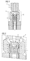
- Figure 1 shows a first embodiment in a cross-sectional view through a fluid injector 2 comprising a housing 4 and a relief valve 6 which is arranged in a cavity 8 having a longitudinal axis L. At its free axial end the cavity 8 comprises a fluid inlet 10 being designed to receive a fluid pipe connector 12. In a preferred embodiment, there is a fluid filter 14 arranged in the cavity 8.
- the fluid injector 2 may be designed as a fuel injector in order to be used to inject fuel into a combustion chamber of an internal combustion engine.
- the fluid pipe connector 12 may be for example part of a fuel rail, being designed to deliver fuel to the fluid injector 2.
- the relief valve 6 comprises a sealing element 16 having three recesses 18a, 18b, 18c, a spring element 20 with a first axial end 22 and a second axial end 24 and a piston 26.
- the sealing element 16 is arranged in the cavity 8 such that a hydraulic communication in the cavity 8 is possible at least through the recess 18a.
- the sealing element 16 may for example be press fitted into the cavity 8.
- the first axial end 22 of the spring element 20 is fixed in relation to the housing 4.
- the second axial end 24 of the spring element 20 is arranged moveable in the cavity 8 facing the fluid inlet 10.
- the piston 26 is arranged in the cavity 8 and coupled to the second axial end 24 of the spring element 20 in order to face the fluid inlet 10.
- FIG. 2 and Figure 3 show the first embodiment of the relief valve 6 in more detail.
- the sealing element 16 comprises the three recesses 18a,18b,18c.
- the piston 26 comprises a closing element 28 having a first side 30 and an opposite second side 32.
- the closing element 28 of the piston 26 is mechanically coupled to the second axial end 24 of the spring element 20.
- the piston 26 further comprises two contact elements 34 which are mechanically coupled to the first side 30 of the closing element 28. Each of the contact elements 34 extends through one recess 18b and 18c of the sealing element 16, respectively.
- the fluid pipe connector 12 is not coupled to the fluid injector 2 so that the contact elements 34 extend into the fluid inlet 10. Due to the pretension of the spring element 20 the piston 26 is pressed against the sealing element 16 such that the closing element 28 of the piston 26 hydraulically seals the recesses 18a, 18b and 18c of the sealing element 16. A hydraulical communication between the fluid inlet 10 and the fluid filter 14 is prevented by the hydraulically sealing engagement between the piston 26 and the sealing element 16.
- the fluid injector 2 is designed to be the fuel injector of the internal combustion engine, this configuration corresponds to a fuel injector which is uncoupled from the fluid reservoir, for example the fuel rail.
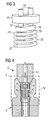
- Figure 4 and Figure 5 show the first embodiment of the relief valve 6 with the fluid pipe connector 12 coupled to the fluid injector 2.
- the fluid pipe connector 12 presses the contact elements 34 against a pre-stressing of the spring element 20 in direction to the fluid filter 14.
- the closing element 28 of the piston 26 is not in contact with the sealing element 16 and a hydraulic communication at least through the recess 18a is enabled. This enables the fluid pipe connector 12 to provide the fluid injector 2 with fluid, for example with fuel.
- the fluid inlet 10 comprises a spherical shape and the fluid pipe connector 12 comprises a conical shape in order to establish a mechanical engagement with a spherical to conical connection. It is for example also possible that the fluid inlet 10 comprises a conical shape and the fluid pipe connector 12 comprises a spherical shape in order to establish a mechanical engagement with a conical to spherical connection between the fluid inlet 10 and the fluid pipe connector 12.
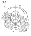
- Figures 6 and 7 show a second embodiment of the relief valve 6. In both figures the relief valve 6 shown is coupled with the fluid pipe connector 12.
- the second embodiment differs from the first embodiment in that the piston 26 comprises a cylindrical contact element 34 having at least one clearance 36 in order to enable a hydraulic communication in the cavity 8 through the clearance 36.
- the closing element 28 of the piston 26 is designed to seal the recess 18a of the sealing element 16 hydraulically in case of a mechanical connection between the closing element 28 and the sealing element 16.
- a piston rod 38 mechanically couples the contact element 34 with the closing element 28, extending through the recess 18a of the sealing element 16 and being arranged in parallel to the longitudinal axis L of the cavity 8.
- the first axial end 22 of the spring element 20 is mechanically coupled with the sealing element 16.
- the advantage of the relief valve 6 according to the first or second embodiment is that upon a mechanical connection of the fluid pipe connector 12 to the fluid injector 2 a hydraulical communication between the fluid pipe connector 12 and the cavity 8 of the fluid injector 2 is established automatically. The contrary is also true.
- the cavity 8 is automatically sealed hydraulically by the relief valve 6. This reduces the risk of fluid leakage through the fluid inlet 10 when the fluid injector 2 is disconnected. Especially, it reduces the risk of a contamination of, for example, a service technician uncoupling the fluid injector 2.
- the absence of components that might move during a fluid flow in the fluid injector 2 further reduces the risk of a contamination of the fluid with particles due to an abrasion of mechanical parts.
Landscapes
- Engineering & Computer Science (AREA)
- General Engineering & Computer Science (AREA)
- Mechanical Engineering (AREA)
- Chemical & Material Sciences (AREA)
- Combustion & Propulsion (AREA)
- Manufacturing & Machinery (AREA)
- Fuel-Injection Apparatus (AREA)
Priority Applications (1)
| Application Number | Priority Date | Filing Date | Title |
|---|---|---|---|
| EP20080017994 EP2177809B1 (de) | 2008-10-14 | 2008-10-14 | Flüssigkeitseinspritzdüse mit Entlastungsventil |
Applications Claiming Priority (1)
| Application Number | Priority Date | Filing Date | Title |
|---|---|---|---|
| EP20080017994 EP2177809B1 (de) | 2008-10-14 | 2008-10-14 | Flüssigkeitseinspritzdüse mit Entlastungsventil |
Publications (2)
| Publication Number | Publication Date |
|---|---|
| EP2177809A1 true EP2177809A1 (de) | 2010-04-21 |
| EP2177809B1 EP2177809B1 (de) | 2012-03-14 |
Family
ID=40352488
Family Applications (1)
| Application Number | Title | Priority Date | Filing Date |
|---|---|---|---|
| EP20080017994 Ceased EP2177809B1 (de) | 2008-10-14 | 2008-10-14 | Flüssigkeitseinspritzdüse mit Entlastungsventil |
Country Status (1)
| Country | Link |
|---|---|
| EP (1) | EP2177809B1 (de) |
Cited By (1)
| Publication number | Priority date | Publication date | Assignee | Title |
|---|---|---|---|---|
| EP2407398A3 (de) * | 2010-07-16 | 2014-07-16 | Wesemann GmbH & Co. KG | Vorrichtung zum Sammeln flüssiger Abfallstoffe |
Citations (5)
| Publication number | Priority date | Publication date | Assignee | Title |
|---|---|---|---|---|
| US4962881A (en) * | 1988-03-28 | 1990-10-16 | Nippon Air Brake K.K. | Flow passage coupling unit |
| US5082244A (en) * | 1990-12-28 | 1992-01-21 | Shippers Paper Products Company | Cargo air bag inflation valve and inflator combination |
| US6089540A (en) | 1997-04-16 | 2000-07-18 | Armaturenfabrik Hermann Voss Gmbh & Co. | Plug-in connection with leakage protection |
| US20010050073A1 (en) * | 2000-02-07 | 2001-12-13 | Siemens Automotive Corporation | Fuel injector and fuel rail check valves |
| EP1589219A1 (de) * | 2004-04-22 | 2005-10-26 | Bayerische Motoren Werke Aktiengesellschaft | Kraftstoff-Verteilerleiste für eine Brennkraftmaschine |
-
2008
- 2008-10-14 EP EP20080017994 patent/EP2177809B1/de not_active Ceased
Patent Citations (5)
| Publication number | Priority date | Publication date | Assignee | Title |
|---|---|---|---|---|
| US4962881A (en) * | 1988-03-28 | 1990-10-16 | Nippon Air Brake K.K. | Flow passage coupling unit |
| US5082244A (en) * | 1990-12-28 | 1992-01-21 | Shippers Paper Products Company | Cargo air bag inflation valve and inflator combination |
| US6089540A (en) | 1997-04-16 | 2000-07-18 | Armaturenfabrik Hermann Voss Gmbh & Co. | Plug-in connection with leakage protection |
| US20010050073A1 (en) * | 2000-02-07 | 2001-12-13 | Siemens Automotive Corporation | Fuel injector and fuel rail check valves |
| EP1589219A1 (de) * | 2004-04-22 | 2005-10-26 | Bayerische Motoren Werke Aktiengesellschaft | Kraftstoff-Verteilerleiste für eine Brennkraftmaschine |
Cited By (1)
| Publication number | Priority date | Publication date | Assignee | Title |
|---|---|---|---|---|
| EP2407398A3 (de) * | 2010-07-16 | 2014-07-16 | Wesemann GmbH & Co. KG | Vorrichtung zum Sammeln flüssiger Abfallstoffe |
Also Published As
| Publication number | Publication date |
|---|---|
| EP2177809B1 (de) | 2012-03-14 |
Similar Documents
| Publication | Publication Date | Title |
|---|---|---|
| US8287256B2 (en) | Valve assembly | |
| KR101504786B1 (ko) | 밸브 부품 | |
| CN101180464B (zh) | 用于内燃机的燃料喷射装置的高压活塞泵 | |
| CN102422020B (zh) | 用于高压活塞燃料泵的阀单元及包括该阀单元的泵 | |
| KR101489133B1 (ko) | 입구 커넥터 | |
| CN111322187B (zh) | 高压燃料供给泵 | |
| CN101983285A (zh) | 用于内燃机的燃料喷射系统 | |
| US7886718B2 (en) | Fuel injector having integral body guide and nozzle case for pressure containment | |
| EP2177809B1 (de) | Flüssigkeitseinspritzdüse mit Entlastungsventil | |
| US6783337B2 (en) | Check valve seal assembly | |
| EP1288486A3 (de) | Leckagekanal in einem Kraftstoffhochdrucksystem | |
| CN205001096U (zh) | 一种单缸柴油机用单体泵总成 | |
| JP5518797B2 (ja) | 内燃機関の燃料供給装置の吸入弁 | |
| JP4585977B2 (ja) | 高圧燃料供給ポンプ及びその組立方法 | |
| CN102713238A (zh) | 用于流体的喷射阀 | |
| CN120344762A (zh) | 燃料泵 | |
| CN102628416A (zh) | 共轨燃料系统的压力恢复系统、燃料喷射器及其操作方法 | |
| CN201241775Y (zh) | 一种超高压柴油机喷油泵 | |
| CN219366202U (zh) | 用于燃料喷射系统的高压泵和用于车辆的燃料喷射系统 | |
| CN219317079U (zh) | 用于车辆的燃油喷射系统及其高压燃油泵 | |
| EP2080895B1 (de) | Thermische Kompensationsanordnung und Einspritzventil | |
| WO2025099163A1 (en) | Supply assembly for a gaseous-fuel engine | |
| CN101634267B (zh) | 一种改良的超高压柴油机喷油泵 | |
| CN113302394A (zh) | 燃料高压泵 | |
| CN205478047U (zh) | 用于高压油泵的外部出油阀以及相应的高压油泵 |
Legal Events
| Date | Code | Title | Description |
|---|---|---|---|
| PUAI | Public reference made under article 153(3) epc to a published international application that has entered the european phase |
Free format text: ORIGINAL CODE: 0009012 |
|
| AK | Designated contracting states |
Kind code of ref document: A1 Designated state(s): AT BE BG CH CY CZ DE DK EE ES FI FR GB GR HR HU IE IS IT LI LT LU LV MC MT NL NO PL PT RO SE SI SK TR |
|
| AX | Request for extension of the european patent |
Extension state: AL BA MK RS |
|
| 17P | Request for examination filed |
Effective date: 20101021 |
|
| AKX | Designation fees paid |
Designated state(s): DE FR IT |
|
| 17Q | First examination report despatched |
Effective date: 20110412 |
|
| GRAP | Despatch of communication of intention to grant a patent |
Free format text: ORIGINAL CODE: EPIDOSNIGR1 |
|
| RTI1 | Title (correction) |
Free format text: FLUID INJECTOR WITH RELIEF VALVE |
|
| GRAS | Grant fee paid |
Free format text: ORIGINAL CODE: EPIDOSNIGR3 |
|
| GRAA | (expected) grant |
Free format text: ORIGINAL CODE: 0009210 |
|
| AK | Designated contracting states |
Kind code of ref document: B1 Designated state(s): DE FR IT |
|
| REG | Reference to a national code |
Ref country code: DE Ref legal event code: R096 Ref document number: 602008014049 Country of ref document: DE Effective date: 20120510 |
|
| PLBE | No opposition filed within time limit |
Free format text: ORIGINAL CODE: 0009261 |
|
| STAA | Information on the status of an ep patent application or granted ep patent |
Free format text: STATUS: NO OPPOSITION FILED WITHIN TIME LIMIT |
|
| 26N | No opposition filed |
Effective date: 20121217 |
|
| REG | Reference to a national code |
Ref country code: DE Ref legal event code: R097 Ref document number: 602008014049 Country of ref document: DE Effective date: 20121217 |
|
| REG | Reference to a national code |
Ref country code: FR Ref legal event code: PLFP Year of fee payment: 8 |
|
| REG | Reference to a national code |
Ref country code: FR Ref legal event code: PLFP Year of fee payment: 9 |
|
| REG | Reference to a national code |
Ref country code: FR Ref legal event code: PLFP Year of fee payment: 10 |
|
| REG | Reference to a national code |
Ref country code: FR Ref legal event code: PLFP Year of fee payment: 11 |
|
| PGFP | Annual fee paid to national office [announced via postgrant information from national office to epo] |
Ref country code: DE Payment date: 20181031 Year of fee payment: 11 |
|
| PGFP | Annual fee paid to national office [announced via postgrant information from national office to epo] |
Ref country code: IT Payment date: 20181024 Year of fee payment: 11 Ref country code: FR Payment date: 20181023 Year of fee payment: 11 |
|
| REG | Reference to a national code |
Ref country code: DE Ref legal event code: R119 Ref document number: 602008014049 Country of ref document: DE |
|
| PG25 | Lapsed in a contracting state [announced via postgrant information from national office to epo] |
Ref country code: DE Free format text: LAPSE BECAUSE OF NON-PAYMENT OF DUE FEES Effective date: 20200501 |
|
| PG25 | Lapsed in a contracting state [announced via postgrant information from national office to epo] |
Ref country code: IT Free format text: LAPSE BECAUSE OF NON-PAYMENT OF DUE FEES Effective date: 20191014 Ref country code: FR Free format text: LAPSE BECAUSE OF NON-PAYMENT OF DUE FEES Effective date: 20191031 |